Page is loading ...

60-000034-1 RevA
1/11/2019
www.criticallink.com
MityCAM-C50000
CMV50000 EVK User’s Manual

CMV50000 EVK User’s Manual
Page 2 of 20 60-000034-1 RevA
1/11/2019
www.criticallink.com
Contents
1 Introduction .................................................................................................................................................... 4
1.1 Additional Documentation ....................................................................................................................................... 4
1.2 Organization .............................................................................................................................................................. 4
2 Interfaces ........................................................................................................................................................ 4
2.1 AIA USB 3 Vision ........................................................................................................................................................ 4
2.2 HDMI ......................................................................................................................................................................... 4
2.3 Power Interface ........................................................................................................................................................ 4
2.4 USB 2.0 RNDIS Debug ............................................................................................................................................... 4
3 Frame Interval and Exposure Time ................................................................................................................... 5
3.1 External Exposure and External Frame Rate............................................................................................................. 5
3.2 External Frame Rate and Internal Exposure ............................................................................................................. 6
3.3 Internal Frame Rate and Internal Exposure .............................................................................................................. 6
3.4 Notes on Frame Interval ........................................................................................................................................... 6
4 Continuous Operation ..................................................................................................................................... 7
4.1 USB Output ............................................................................................................................................................... 7
4.2 HDMI Output ............................................................................................................................................................ 7
4.3 Simultaneous Output ................................................................................................................................................ 7
5 Changing LVDS Clock Rate ................................................................................................................................ 7
6 Burst Mode Operation ..................................................................................................................................... 7
6.1 USB 3 Output ............................................................................................................................................................ 7
6.2 HDMI ......................................................................................................................................................................... 7
7 Configurable Region of Interest........................................................................................................................ 8
7.1 U3V ........................................................................................................................................................................... 8
7.2 HDMI ......................................................................................................................................................................... 8
8 Optical Black Data ........................................................................................................................................... 8
9 Color Processing .............................................................................................................................................. 9
10 GPIO Interface ............................................................................................................................................... 9
10.1 Input ...................................................................................................................................................................... 10
10.2 Output ................................................................................................................................................................... 10
11 Firmware Upgrade ....................................................................................................................................... 10
12 MityCAMC50000M GenICam Features .......................................................................................................... 10
12.1 Device Control Group ........................................................................................................................................... 11
12.2 Image Format Control Group ................................................................................................................................ 11
12.3 Acquisition Control Group .................................................................................................................................... 13
12.4 Sensor Peek/Poke Group ...................................................................................................................................... 14
12.5 Sensor Specific Group ........................................................................................................................................... 14
12.6 Digital IO Control Group ....................................................................................................................................... 16
12.7 HDMI Control Group ............................................................................................................................................. 16
12.8 Transport Layer Control Group ............................................................................................................................. 19
13 Revision History........................................................................................................................................... 19
Figures
Figure 1 Sensor Connections Relating to Frame Exposure and Timing Control ........................................................... 5
Figure 2 CMV50000 Pixel Array .................................................................................................................................... 8

CMV50000 EVK User’s Manual
Page 3 of 20 60-000034-1 RevA
1/11/2019
www.criticallink.com
Tables
Table 1: Reference Documentation .............................................................................................................................. 4
Table 2 GPIO Break Out Cable Pin Assignments ........................................................................................................... 9
Table 3: GPIO Modes .................................................................................................................................................... 9

CMV50000 EVK User’s Manual
Page 4 of 20 60-000034-1 RevA
1/11/2019
www.criticallink.com
1 Introduction
The purpose of this document is to detail features of the CMV50000 EVK, which includes a MityCAM-C50000
camera head.
1.1 Additional Documentation
In addition to this document, the following documents are also useful / pertinent to the use and operation of the
MityCAM-C50000 cameras.
Table 1: Reference Documentation
Document
#
Title
Description
DS000522
CMV50000 Datasheet
CMV50000 47.5MP CMOS Machine Vi
sion Image Sensor
Datahseet. See www.ams.com
60
-
000
030
MityCAM
-
C
50000
datasheet
Complete
specification for MityCAM
-
C
50
000.
U3V
Vision Standard
1.0.1
See
https://www.visiononline.org/vision
-
standards
-
details.cfm?type=11
GenTL Viewer User
’
s
Manual
Users guide for the Critical Link Supplied GenTL Viewer PC
software.
1.2 Organization
This document is organized in sections covering a specific topic.
2 Interfaces
2.1 AIA USB 3 Vision
The MityCAM-C50000 includes a USB 3.0 interface that is complaint with the AIA USB 3.0 Vision standard (U3V).
This is the main control and data interface to the camera system. A list of the GenICam registers available for
control of the system included in Section 12 of this document.
Critical Link supplies a free pc application that may be used to control, capture and save images generated by the
evaluation kit. However, this kit should also be compatible with any third-party software that is complaint with
the U3V standard, such as the National Instruments Vision Acquisition Software, HALCON, etc. Figures in this
document are captured using the Critical Link provided software.
2.2 HDMI
The MityCAM-C50000 includes an HDMI output interface port. This port will support 1080P 24 bit-per-pixel RGB
output as well as UHD 4K (30 Hz) output for sensor preview. Configuration of the HDMI output mode is controlled
through the GenICAM HdmiOutputResolution register. The interface port must use an HDMI 1.4 compliant
interface cable and suitable monitor.
2.3 Power Interface
The MityCAM-C50000 kit requires a +12 V input voltage supply. A minimum of 2 Amps is required. See the
datasheet for details on the connector.
2.4 USB 2.0 RNDIS Debug

CMV50000 EVK User’s Manual
Page 5 of 20 60-000034-1 RevA
1/11/2019
www.criticallink.com
The USB 2.0 port on the MityCAM-C50000 kit provides an RNDIS (ethernet) connection to an attached HOST PC.
The port is configured to run a DHCP server and present an ethernet IP address of 10.45.45.1/8 for the camera
and assign an address of 10.45.45.10/8 to the attached HOST PC. The camera supports accessing the embedded
linux shell on the device using the ssh protocol. Using this protocol it is also possible to transfer files onto the
camera subsystem. There is also a simple web-server running on the camera to support firmware upgrades.
3 Frame Interval and Exposure Time
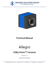
Control of the Frame Interval and Exposure Time can be performed both internally and externally on the kit using
the GenICam control registers and (for the case of external control) the GPIO IO pins on J201. The block diagram
shows how the kit interfaces with the CMV50000 sensor.
Figure 1 Sensor Connections Relating to Frame Exposure and Timing Control
3.1 External Exposure and External Frame Rate
This mode uses Control Mode 0 (Full External) mode of the CMV50000 as described by the CTRL_MODE register in
the sensor datasheet. In this mode GPIO IO 0 (pin 1) and GPIO IO 1 (pin 2) of the P201 cable interface are used as
the REQ_EXP and REQ_FRAME signals, respectively. To configure this mode, the following GenICAM registers of
the camera should be configured:
Register
Setting
LineMode[0]
Input
LineMode[1]
Input
TriggerMode
On
InternalExposureMode
False
Note, instead of the GPIO IO 0 and GPIO IO 1, the optical input pins may be used with the following GenICAM
settings:
Register
Setting
LineMode[0]
OptoInput
LineMode[1]
OptoInput
TriggerMode
On

CMV50000 EVK User’s Manual
Page 6 of 20 60-000034-1 RevA
1/11/2019
www.criticallink.com
InternalExposureMode
False
The timing of the external exposure and frame rate must be consistent with the capabilities of the CMV50000
Sensor.
3.2 External Frame Rate and Internal Exposure
This mode uses Control Mode 1 (Programmed External) mode of the CMV50000 as described by the CTRL_MODE
register in the sensor datasheet. In this mode GPIO IO 0 (pin 1) of the P201 cable interface is used as the REQ_EXP
signals, respectively. To configure this mode, the following GenICAM registers of the camera should be
configured:
GenICam
Register
Setting
LineMode[0]
Input
LineMode[1]
Input
TriggerMode
On
ExposureTime
User Required Exposure Time
InternalExposureMode
True
Note, instead of the GPIO IO 0, the optical input pins may be used with the following GenICAM settings:
GenICam
Register
Setting
LineMode[0]
OptoInput
LineMode[1]
OptoInput
TriggerMode
On
ExposureTime
User Required Exposure Time
InternalExposureMode
True
3.3 Internal Frame Rate and Internal Exposure
This mode uses Control Mode 1 (Programmed External) mode of the CMV50000, but the FPGA drives the
REQ_EXP signal using an internally generated timer based on the GenICAM frame time register. To configure this
mode, the following GenICAM registers of the camera should be configured:
GenICam
Register
Setting
TriggerMode
Off
ExposureTime
User Required Exposure Time
AcquisitionFrameRate or AcquisitionFramePeriod
User Required
Sensor Frame Rate
InternalExposureMode
True
3.4 Notes on Frame Interval
The maximum frame interval time is defined in the CMV50000 datasheet. For a full ROI, up to 30 Hz may be
achieved. For ROIs that are smaller in height, higher frame rates out of the sensor are possible. However, the
USB 3.1 interface is limited to approximately 400 MB/sec. So, for a full ROI image at 12 bits per pixel, the
maximum continuous framerate achievable is limited to approximately 6 Hz. For continuous operation, if the

CMV50000 EVK User’s Manual
Page 7 of 20 60-000034-1 RevA
1/11/2019
www.criticallink.com
requested frame rate is higher than can be achieved, frames will be periodically dropped on the USB output
interface.
4 Continuous Operation
4.1 USB Output
When the GenICam AcquisitionMode register is set to Continuous and acquisition is started, the camera will
configure the sensor to operate at the requested FrameRate and start transmitting data to the USB 3.0 interface.
If the requested data rate exceeds the capability of the USB 3.0 link, the camera will periodically drop incoming
frames prior to transmission to the host PC in order to reduce the latency of the data shown on a host PC display.
4.2 HDMI Output
The HDMI output supports operation at UHD 4K resolution at 30 Hz, or 1080P resolution at 60 Hz based on the
HdmiOutputResolution GenICam parameter. Frames received by the sensor are clipped according to the
HdmiOffsetX, HdmiOffsetY, HdmiWidth, and HdmiHeight GenICam parameters, converted to RGB colorspace
based on the HdmiColor parameter, rate converted (via frame dropping or frame repeating), and transmitted to
the HDMI display as the received from the sensor. The latency of the HDMI output is typically 1-2 frames (~66 ms
at UHD 4K resolution).
The HDMI output is enabled and disabled using GenICam HdmiStart and HdmiStop commands.
4.3 Simultaneous Output
The MityCAM-C50000 EVK supports both running both the USB output and the HDMI output at the same time.
5 Changing LVDS Clock Rate
The camera supports operating the LVDS serializer rates of the CMV50000 at different frequencies up to the
maximum 830 MHz. The data rate of the lanes is configurable using the SensorClockSpeed GenICam parameter.
Lowering the maximum clock rate will reduce power consumed by the sensor and processor, but will reduce the
maximum possible framerate for a given resolution. For a full ROI, the maximum frame rate from the sensor will
scale by approximately
𝐹𝑟𝑎𝑚𝑒𝑅𝑎𝑡𝑒𝐹𝑟𝑎𝑚𝑒𝑅𝑎𝑡𝑒
≈
30 𝐹
830
6 Burst Mode Operation
6.1 USB 3 Output
The camera has a section of RAM dedicated as a circular image buffer. When the AcquisitionMode GenICam
register is set to Single or Multi-Frame, data will be streamed at the configured rate into the image buffer and
streamed out at the maximum achievable rate on the USB 3.0 interface, which is approximately 400 MB/sec.
6.2 HDMI
When the HDMI output is enabled, the maximum frame rate generated by the sensor must be less than or equal
to 30 Hz for 4K operation, or 60 Hz for 1080P operation, otherwise undefined behavior may occur.

CMV50000 EVK User’s Manual
Page 8 of 20 60-000034-1 RevA
1/11/2019
www.criticallink.com
7 Configurable Region of Interest
While the CMV50000 supports multiple ROI, the MityCAM-C50000 supports a single ROI.
7.1 U3V
The base ROI captured from the Sensor and transmitted via the U3V interfaces is configured using the GenICam
defined Width, Height, OffsetX, and OffsetY registers while the camera is IDLE.
7.2 HDMI
The HDMI ROI is configured using the GenICam parameters in the HDMI control group: HdmiOffsetX,
HdmiOffsetY, HdmiWidth, and HdmiHeight. These parameters are relative to the U3V Width, Height, OffsetX, and
OffsetY registers. So if the sensor ROI is configured to start at offset (1024,1024), then the HDMI display will be
start at (1024+HdmiOffsetX, 1024+HdmiOffsetY).
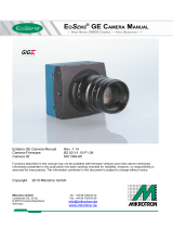
8 Optical Black Data
The CMV50000 uses optical black data for offset bias correction on a row by row basis. The CMV50000 includes
68 optical black columns on both the left and right side of the array as is shown in the figure below (taken from
the CMV50000 datasheet).
Figure 2 CMV50000 Pixel Array
The MityCAM-C50000 kit provides access to the top and bottom 22 buffer pixel rows and access to the left and
right 68 OB column pixels by adjusting the request ROI of the camera. The camera presents the buffered pixel
rows at the top and bottom positions in the ROI. The camera packs the 68 optical black pixels in 2 groups of 96

CMV50000 EVK User’s Manual
Page 9 of 20 60-000034-1 RevA
1/11/2019
www.criticallink.com
pixels (192 total) at the right side of the ROI. The right most 192 pixels, starting at pixel X offset of 7920, will
consist of the 68 optical black pixels on the left side of the array followed by 28 padded pixels followed by 68
optical black pixels on the right side of the array followed by 28 padded pixels. The 28 padded pixels should be
ignored.
The nominal ROI that will capture the Effective pixels should be specified as having a X offset of 0, a Y offset of 22,
a width of 7920 and a height of 6004. To capture the black pixels on the column the ROI should have an X offset
of 0, a Y offset of 22, a width of 8112, and a height of 6004. To capture the black pixels and the buffer row pixels,
the ROI should have an X offset = 0, a Y offset = 0, a width of 8112 and a height of 6048.
9 Color Processing
10 GPIO Interface
The EVK comes with a breakout cable for the GPIO interface harness. The pin connections are listed in Table 2.
P1 is the 12-Pin GPIO connector interface. P2 is the USB Type A interface for Host PC insertion. P3 is the 9 Pin
receptacle (female) cable end. P4 is the 9 pin plug (male) cable end.
Table 2 GPIO Break Out Cable Pin Assignments
GPIO Port
(P1)
Break Out Cable Port
-
Pin
Description
1
P3
-
6
FPGA IO 0 – 1.8V CMOS Logic Level
2
P3
-
7
FPGA IO 1 – 1.8V CMOS Logic Level
3
P3
-
8
FPGA IO 2 – 1.8V CMOS Logic Level
4
P3
-
9
FPGA IO 3 – 1.8V CMOS Logic Level
5
P3
-
4
Camera shutdown, short to GND to turn off camera,
otherwise leave unconnected.
6
P3
-
5
Ground
7
USB
-
A Connector
, P2
1.8V Serial Console Output
8
USB
-
A Connector
, P2
1.8V Serial Console Input
9
P
4
-
5
Reference / Return for Isolated input currents.
10
P4
-
6
Opto-isolated Input 0
11
P4
-
7
Opto-isolated Input 1
12
P4
-
8
Opto-isolated Input 2
The available modes of operation for the 4 GPIO pins are listed in Table 3.
Table 3: GPIO Modes
#
Mode
1.
Input for reading
2.
Output driven low
3.
Output driven high
4.
Input for external trigger
The following sections will cover Modes 1, 2 and 3. Mode 4 is covered in separate sections.

CMV50000 EVK User’s Manual
Page 10 of 20 60-000034-1 RevA
1/11/2019
www.criticallink.com
The Opto-Isolated Input pins may be used as inputs for reading. Input 0 may be used as an optional trigger source
in the same way as GPIO 0.
10.1 Input
In the input mode of operation, the pin can be queried for its current logical value (High or Low).
10.2 Output
In output mode, the pin can be driven high or low. This can be used to toggle a light source or some other
operation.
11 Firmware Upgrade
Recent versions of the MityCAM-C50000 allow upgrading the firmware via the network interface. Details for
acquiring the firmware and downloading the firmware to the camera are available on the Critical Link MityCAM
Support Site.
12 MityCAMC50000M GenICam Features
This section presents a summary of the Generic Interface for Cameras (GenICam) available
features provided by the camera. Many of the listed features, identified by the SFNC=Y field,
are defined by the european machine vision association (emva) Standard Features Naming
Convention.

CMV50000 EVK User’s Manual
Page 11 of 20 60-000034-1 RevA
1/11/2019
www.criticallink.com
12.1 Device Control Group
Feature
Type
SFNC?
Description
DeviceReset
Command
Y
This command is used to reset the device and to put it in its
power up state.
DeviceVendorName
StringReg
Y
Name of camera vendor
DeviceModelName
StringReg
Y
Name of the camera model
DeviceManufacturerInfo
StringReg
Y
Manufacturer Info
DeviceVersion
StringReg
Y
Device Version
DeviceSerialNumber
StringReg
Y
Displays the factory set camera serial number.
DeviceFirmwareVersion
StringReg
Y
Firmware Version
DeviceSFNCVersionMajor
Integer
Y
Major version of the Standard Features Naming Convention
that was used to create GenICam XML
DeviceSFNCVersionMinor
Integer
Y
Minor version of the Standard Features Naming Convention
that was used to create GenICam XML
De
viceSFNCVersionSubMinor
Integer
Y
Sub
-
Minor version of the Standard Features Naming
Convention that was used to create GenICam XML
SensorTemperature
Float
Y
Sensor temperature in degrees C.
Min Value:-200.0
Max Value:200.0
CalibrationMode
Enumeration
Y
Calibration type to run when issuing calibration command.
Allowed Values :
Dark
White
Calibration
Command
N
This command cause
the camera to calibrate column level
offset and gain correction Tables. Requires the sensor to
covered (dark).
12.2 Image Format Control Group
Feature
Type
SFNC?
Description
OffsetX
Integer
Y
X offset of image, in pixels.
Min Value:0
Increment:1
OffsetY
Integer
Y
Y offset of image, in pixels.
Min Value:0
Increment:1
Width
Integer
Y
Width of image, in pixels.

CMV50000 EVK User’s Manual
Page 12 of 20 60-000034-1 RevA
1/11/2019
www.criticallink.com
Min Value:16
Increment:16
Height
Integer
Y
Height of image, in pixels.
Min Value:1
Increment:1
PixelFormat
Enumeration
Y
Pixel
format
Allowed Values :
Mono12p
Mono8
BayerBG8
BayerBG12P
TestPattern
Enumeration
Y
This control allows the user to select between normal Sensor
Data and the CMV50000 sensor channel test gradient test
data as described in 7.8.5 of the CMV50000 datasheet.
Allowed Values :
SensorData
SensorGradient
BadPixelReplacementEnable
Enumeration
N
This control allows the user to enable or disable the
replacement of pixels marked as bad by the system.
Allowed Values :
On
Off
BadPixelReplacementMap
Enumeration
N
When on, marked bad pixels are set to 0 and non
-
marked
pixels are set to maximum value during image transmission.
Allowed Values :
On
Off
SensorClockSpeed
Integer
N
This control allows the user to configure the LVDS data rate
(in Mbps) transmitted from the sensor to the evaluation
camera FPGA. By default the system sets this to the
maximum rate. Reducing the LVDS data rate will impact the

CMV50000 EVK User’s Manual
Page 13 of 20 60-000034-1 RevA
1/11/2019
www.criticallink.com
maximum frame rate achievable
by the sensor.
Min Value:200
Max Value:830
12.3 Acquisition Control Group
Feature
Type
SFNC?
Description
AcquisitionMode
Enumeration
Y
Acquisition mode
Allowed Values :
Continuous
SingleFrame
MultiFrame
AcquisitionStart
Command
Y
Start
acquisition.
AcquisitionStop
Command
Y
Stop acquisition.
ExposureTime
Float
Y
Exposure duration, in microseconds.
Min Value:10.0
Max Value:10000000.0
AcquisitionFrameRate
Converter
Y
Frame rate, in frames per second.
AcquisitionFramePeriod
Integer
Y
Frame rate, in microseconds.
Min Value:1000
Max Value:5000000
Increment:1
AcquisitionFrameCount
Integer
Y
Number of frames to aquire in MultiFrame Acquisition mode.
Min Value:1
Max Value:1000
Increment:1
TriggerSelector
Enumeration
Y
TriggerSelector
Allowed Values :
FrameStart
TriggerMode
Enumeration
N
TriggerMode
Allowed Values :
Off

CMV50000 EVK User’s Manual
Page 14 of 20 60-000034-1 RevA
1/11/2019
www.criticallink.com
On
TriggerActivation
Enumeration
N
TriggerActivation
Allowed Values :
RisingEdge
12.4 Sensor Peek/Poke Group
Feature
Type
SFNC?
Description
RegAddress
Integer
N
Register address of the Peek/Poke
Min Value:0
Max Value:255
Increment:1
RegValue
Integer
N
Value of the address peeked or to be written when poked
Min Value:0
Max Value:255
Increment:1
ExecRead
Command
N
Command reads and invalidates/replaces the RegValue register with the setting
read back from the sensor.
ExecWrite
Command
N
Command writes the value stored in the RegValue register to the sensor at the
specified RegAddress location.
12.5 Sensor Specific Group
Feature
Type
SFNC?
Description
DMUX1_SEL
Enumeration
N
This control allows routing various sensor timing signals to the TDIG test
point on the sensor board. See section 8.2.62 of the datasheet.
Allowed Values :
None
PLL_1_LOCK
PLL_2_LOCK
CLK_PIX
INT_REQ_FRAME
INT_REQ_EXP_L
GLOB_Start
CTR_EXP_L
GANA
Enumeration
N
Sensor Analog Gain Selection

CMV50000 EVK User’s Manual
Page 15 of 20 60-000034-1 RevA
1/11/2019
www.criticallink.com
Allowed Values :
Gain_1x
Gain_2x
Gain_4x
GDIG_RE_CE
Integer
N
Digital Gain for Even Rows, Even Columns. See section 7.7.2 of
the
CMV50000 datasheet.
Min Value:0
Max Value:255
Increment:1
GDIG_RE_CO
Integer
N
Digital Gain for Even Rows, Odd Columns. See section 7.7.2 of the
CMV50000 datasheet.
Min Value:0
Max Value:255
Increment:1
GDIG_RO_CE
Integer
N
Digital Gain for Odd
Rows, Even Columns. See section 7.7.2 of the
CMV50000 datasheet.
Min Value:0
Max Value:255
Increment:1
GDIG_RO_CO
Integer
N
Digital Gain for Odd Rows, Odd Columns. See section 7.7.2 of the
CMV50000 datasheet.
Min Value:0
Max Value:255
Increment:1
EOB_DISABLE
Boolean
N
This register will disable (bypass) the Optical Black Correction logic on the
sensor. See section 8.2.59 of the CMV50000 datasheet.
EOB_VALUE
Integer
N
This register will disable (bypass) the Optical Black
Correction logic on the
sensor. See section 8.2.59 of the CMV50000 datasheet.
Min Value:0
Max Value:16384
Increment:1
EOB_TARGET
Integer
N
Target black level, in counts, that sensor normalizes to when optical black
correction is enabled. See section 8.2.36 of the sensor datasheet.
Min Value:0
Max Value:16384
Increment:1

CMV50000 EVK User’s Manual
Page 16 of 20 60-000034-1 RevA
1/11/2019
www.criticallink.com
12.6 Digital IO Control Group
Feature
Type
SFNC?
Description
LineSelector
Enumeration
Y
Selects the physical line (or pin) of the external device connector or
the virtual line of the Transport Layer to configure. When a Line is
selected, all the other Line features will be applied to its associated
I/O control block and will condition the resulting input or output
signal. For this case, Line0-3 correspond to High Speed FPGA IO
numbers 1-4 on the GPIO connector interface.
Allowed Values :
Line0
Line1
Line2
Line3
LineMode
Enumeration
Y
LineMode
Allowed Values :
Input
Output
OptoInput
LineSource
Enumeration
Y
LineSource
Allowed Values :
Off
ExposureActive
UserOutput0
UserOutput1
UserOutputSelector
Enumeration
Y
UserOutputSelector
Allowed Values :
UserOutput0
UserOutput1
UserOutputValue
Boolean
Y
Selecting high and low for the user output.
12.7 HDMI Control Group

CMV50000 EVK User’s Manual
Page 17 of 20 60-000034-1 RevA
1/11/2019
www.criticallink.com
Feature
Type
SFNC?
Description
HdmiStart
Command
N
This command will cause the evalation kit to configure the Sensor
to capture images, scale and output them to the HDMI port
according to the settings in the HDMI Control group.
HdmiStop
Command
N
This command will cause the evalation
kit to configure the Sensor
to stop sending data to the HDMI output port.
HdmiColor
Boolean
N
Setting this parameter to true will cause the RAW input to be
assumed as a Bayer Pattern color image. It will be converted RGB
using a nearest neighbor conversion algorithm for transmission to
the HDMI output display. Setting this parameter to false will cause
the image to be converted to grayscale RGB.
HdmiOffsetX
Integer
Y
X pixel offset of the clipping region of the captured sensor image
that will be routed to the HDMI display. Note: This offset is with
respect to the effective region transmitted to the USB 3 interface
port as defined by the OffsetX parameter.
Min Value:0
Increment:1
HdmiOffsetY
Integer
Y
Y pixel offset of the clipping region of the captured sensor image
that will be routed to the HDMI display.Note: This offset is with
respect to the effective region transmitted to the USB 3 interface
port as defined by the OffsetY parameter.
Min Value:0
Increment:1
HdmiHeight
Integer
Y
Pixel Height of the image sent to the HDMI output interface. Note:
the image sent to the HDMI output interface will be scaled (up or
down depending on the scenario) to match the configured
HdmiOutputResolution parameter. Aspect ratio is not preserved.
Min Value:1
Increment:1
HdmiWidth
Integer
Y
Pixel Width of the image sent to the HDMI output interface. Note:
the image sent to the HDMI output interface will be scaled (up or
down depending on the scenario) to match the configured
HdmiOutputResolution parameter. Aspect ratio is not preserved.
Min Value:16
Increment:16
HdmiOutputResolution
Enumeration
N
Selects the transmitted output resolution on the HDMI interface.
Currently, 1080P60 and UHD 4K at 30 Hz are supported.
Allowed Values :
Res_1080p

CMV50000 EVK User’s Manual
Page 18 of 20 60-000034-1 RevA
1/11/2019
www.criticallink.com
Res_4K

CMV50000 EVK User’s Manual
Page 19 of 20 60-000034-1 RevA
1/11/2019
www.criticallink.com
HdmiGamma
Float
N
The evalation
system will perform a gamma gain conversion of the
HDMI output data using this parameter.
12.8 Transport Layer Control Group
Feature
Type
SFNC?
Description
PayloadSize
Integer
Y
Size of payload, in bytes
Min Value:16
Max Value:95103360
Increment:1
13 Revision History
Revision
Date
Author
Description
-
0
5
/2
2
/201
8
Mike Williamson
Outline / Draft.
A
01/11/2019
Mike Williamson
I
ni
tial Release.

CMV50000 EVK User’s Manual
Page 20 of 20 60-000034-1 RevA
1/11/2019
www.criticallink.com
/