Model BCF-24/65/110, BCM-110
2-8. DOOR FRAME HEATER 1. Remove the electrical power to the unit.
To avoid electrical shock or property damage, move the
power switch to OFF and disconnect main circuit breaker,
or unplug cord at wall receptacle.
2. Remove the door to the unit by removing the screws in the
lower hinge of the door.
3. Remove the control box from the unit, following steps 2
through 5 in the Control Board Section.
3. Remove the plastic tabs that secures the decorator covers
around the door opening, and remove the covers.
4. Peel the heater out of the groove and disconnect the wires
(inside control box) to the element, and remove the element
from the unit.
5. Install new heater in reverse order and press the plastic tabs
in place to secure the decorator covers (tabs included with new
heater).
2-9. EVAPORATOR FAN 1. Remove the electrical power to the unit.
To avoid electrical shock or property damage, move the
power switch to OFF and disconnect main circuit breaker,
or unplug cord at wall receptacle.
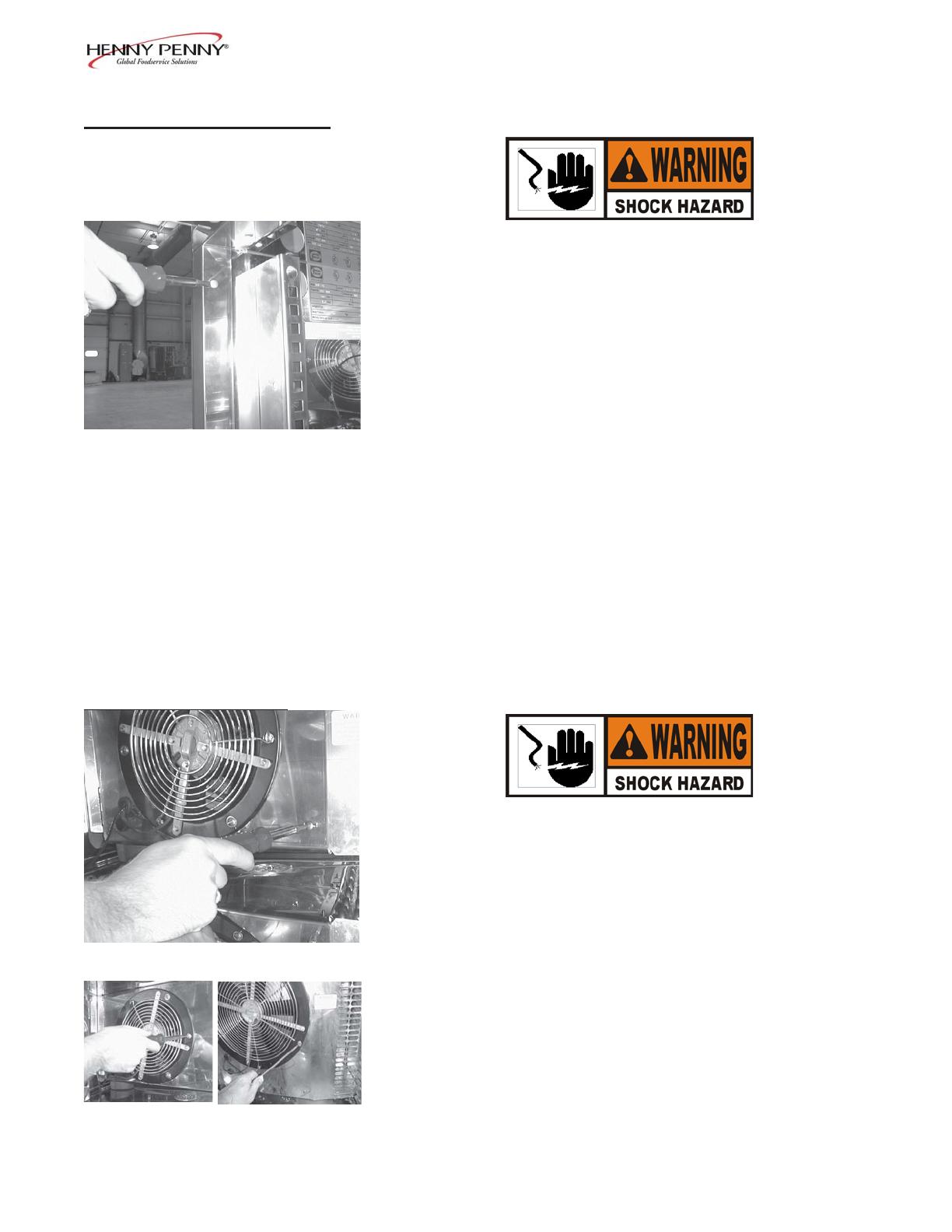
2. Using a Phillips head screwdriver, remove the two screws
securing the fan shroud, and pull out on the shroud.
3. Using a Phillips head screwdriver, remove the three screws
securing the fan guard, and remove the guard.
4. Remove the control box from the unit, following steps 2
through 5 in the Control Board Section.
5. Disconnect the wires (inside control box) to the fan.
6. Remove the three screws securing the fan to the evaporator
door, and pull the fan from the unit.
7. Install new fan in reverse order.
2-4 205


