Page is loading ...

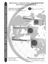
Models:
CROWN09HP230V1A
CROWN12HP230V1A
CROWN18HP230V1A
HIGH-WALL DUCTLESS
AIR CONDITIONING & HEATING SYSTEM
INSTALLATION MANUAL

Table of Contents
Safety Precautions . . . . . . . . . . . . . . . . . . . . . . . . . . . . . . . . . . . . . . . . . . . 2-3
Nomenclature . . . . . . . . . . . . . . . . . . . . . . . . . . . . . . . . . . . . . . . . . . . . . . . . 4
System Requirements . . . . . . . . . . . . . . . . . . . . . . . . . . . . . . . . . . . . . . . . . . 5
Suggested Tools . . . . . . . . . . . . . . . . . . . . . . . . . . . . . . . . . . . . . . . . . . . . . . 6
Part Names . . . . . . . . . . . . . . . . . . . . . . . . . . . . . . . . . . . . . . . . . . . . . . . . . . 7
Installation Site Instructions . . . . . . . . . . . . . . . . . . . . . . . . . . . . . . . . . . . 8-9
Indoor Unit Installation . . . . . . . . . . . . . . . . . . . . . . . . . . . . . . . . . . . . . . . . 10
Outdoor Unit Installation . . . . . . . . . . . . . . . . . . . . . . . . . . . . . . . . . . . . 11-12
Piping Installation . . . . . . . . . . . . . . . . . . . . . . . . . . . . . . . . . . . . . . . . . 13-16
Power and Wiring Installation . . . . . . . . . . . . . . . . . . . . . . . . . . . . . . . . 17-19
Testing and Inspection . . . . . . . . . . . . . . . . . . . . . . . . . . . . . . . . . . . . . . 20-23
Troubleshooting . . . . . . . . . . . . . . . . . . . . . . . . . . . . . . . . . . . . . . . . . . . 24-25
Diagnostic Codes . . . . . . . . . . . . . . . . . . . . . . . . . . . . . . . . . . . . . . . . . . 26-28
Care and Cleaning . . . . . . . . . . . . . . . . . . . . . . . . . . . . . . . . . . . . . . . . . . . 29
Thank you for choosing a Crown
High-Wall Unit for your customer.
Please read this installation manual carefully before installing and starting up the
Crown System. Take a moment to fill out the product and installation form on the
back cover. Retain both the manual and installation record for future reference.

2
SAFETY PRECAUTIONS
Please read the following before operation.
Recognize safety information. This is the safety-alert symbol. When you see this
symbol on the unit and in instructions or manuals, be alert to the potential for personal
injury. Understand these signal words: DANGER, WARNING, and CAUTION. These
words are used with the safety-alert symbol.
DANGER identifies the most serious hazards which will result in severe personal injury
or death.
WARNING signifies hazards which could result in personal injury or death.
CAUTION is used to identify unsafe practices which may result in minor personal
injury or product and property damage.
NOTE is used to highlight suggestions which will result in enhanced installation,
reliability, or operation.
This appliance is not intended for use by children without responsible adult supervision.
Proper care should be taken to ensure safety.
Heat pumps, air conditioners & heating equipment should be installed, started up, and
serviced only by qualified installers and service technicians. Air conditioning, heat pumps
and refrigeration systems are hazardous due to high voltage electrical components,
high refrigerant pressures, and moving parts.
N
O
T
E
:
Y
o
u
r
a
c
t
u
a
l
a
i
r
c
o
n
d
i
t
i
o
n
i
n
g
&
h
e
a
t
i
n
g
s
y
s
t
e
m
a
n
d
r
e
l
a
t
e
d
d
e
v
i
c
e
s
m
a
y
d
i
f
f
e
r
f
r
o
m
t
h
e
i
m
a
g
e
s
s
h
o
w
n
i
n
t
h
i
s
m
a
n
u
a
l
.
W
A
R
N
I
N
G
W
A
R
N
I
N
G

SAFETY PRECAUTIONS
• The unit should be installed and serviced only by trained, qualified installers and service
technicians. Untrained personnel can perform basic maintenance functions such as
cleaning coils. All other operations should be performed by trained service personnel.
• Owner should be cautioned that children should not play with the appliance.
ELECTRICAL SHOCK HAZARD
Failure to follow this warning could result in personal injury or death.
• Before installing, servicing or modifying the system, the main electrical disconnect
switch must be in the OFF position. There may be more than one disconnect switch.
Lock out and tag all switches with a warning label.
General Safety Precautions
• A dedicated power supply circuit should be used in accordance with local electrical
safety regulations and National Electrical Codes (NEC).
• Ensure that the entire system is properly grounded.
• Use a properly sized circuit breaker to protect equipment against short circuit and
overload conditions.
• The system must be positioned at least 5 feet from combustible surfaces.
• Observe all local codes and regulations.
Installation Site Instructions
A proper installation site is vital for correct and reliable operation of the system.
Avoid the following installation locations :
• High heat sources, vapors, flammable gas or volatile liquids.
• High-frequency electro-magnetic waves, generated by radio equipment, welders
or medical equipment.
3
WARNING
WARNING

CROWN
Cooling Capacity
09 - 9,000 BTUH
12 - 12,000 BTUH
18 - 18,000 BTUH
Series Designation
Revision Level
Style/Color Designation
Example: CROWN12HP230V1AO
O12 HP 230V 1A
TERRA
RIO
NEO
CROWN
Model Type
AC - Cooling Only
HP - Heat Pump
Product Type
S - System
O - Outdoor units
H - Indoor High Wall
Electrical Rating
230V - 208/230V 60Hz 1PH
NOMENCLATURE
4

5
SYSTEM REQUIREMENTS
REFRIGERANT CHARGE
ELECTRICAL REQUIREMENTS
PIPE SIZE in (mm)
Notes: 1) System must be on a single dedicated circuit.
2) Power for indoor unit originates from outdoor unit.
3) Use table above for sizing of wiring and circuit breakers.
4) Follow all local building codes and NEC (National Electrical Code) regulations.
Interconnecting Cable: Recommended cable-14/4 A WG stranded bare copper conductors THHN 600V unshielded wire
Note: Use shielded cable if installation is in close proximity of RF and EMI transmitting devices.
Condensate Drain Size: 5/8-in OD 7/16-in ID
Unit Size (BtuH) Liquid Line Suction/Gas Line
9,000 1/4 (6) 1/2 (12)
12,000 1/4 (6) 1/2 (12)
18,000 1/4 (6) 5/8 (15)
Unit Size (BtuH) Min Line Length Max Line Length Max Elevation
9,000 10 (3) 25 (7.5) 49 (15) 33 (10)
12,000 10 (3) 25 (7.5) 66 (20) 33 (10)
18,000 10 (3) 25 (7.5) 82 (25) 33 (10)
U
n
it
Size
(B
t
u
H
)
R
efr
ig
eran
t
Typ
e
F
act
o
r
y
Syst
em
C
h
ar
g
e
A
d
d
it
io
n
al
C
h
ar
g
e
o
z
(kg
)
o
z/ft
(g
/m)
9,
000
R410A
49.
4
(1.
4)
0.
2
(
20)
12,
000
R410A
49.
4
(
1.
4)
0.
2
(20)
18,000
R410A
70.6 (2.0)
0.5 (50)
Unit Size
Voltage
Min Circuit Max Overcurrent Main Power
(BtuH) Amps (MCA) Protection (MOP) Wire Size (AWG)*
9,000 208/230v - 1ph 60hz 12 15 14-2
12,000 208/230v - 1ph 60hz 13 20 12-2
18,000 208/230v - 1ph 60hz 19 30 10-2
*Main power wire from electrical panel to outdoor unit.
REFRIGERANT LINE LENGTHS ft (m)
Pre-Charge
Line Length

• Standard Wrench
• Adjustable/Crescent Wrench
• Torque Wrench
• Hex Keys or Allen Wrenches
• Drill & Drill Bits
• Hole Saw
• Pipe Cutter
• Screw drivers (Phillips & Flat blade)
• Manifold and Gauges
• Level
• R410A Flaring Tool
• Clamp on Amp Meter
• Vacuum Pump
• Safety Glasses
• Work Gloves
• Refrigerant Scale
• Micron Gauge
SUGGESTED TOOLS
6

PART NAMES
Indoor unit
Part Name
1. Front Panel
2. Filter
3. Remote Controller
4. Inter-Connection Wire
5. Drain Hose
6. Refrigerant Lines
Outdoor unit
3
Air outlet
Air inlet
Air inlet
Air outlet
2
1
4
5
6
7

8
INSTALLATION SITE INSTRUCTIONS
Indoor Unit
Select a site that allows for the following:
1. Ensure the installation complies with the installation minimum dimensions (defined below)
and meets the minimum and maximum connecting piping length and maximum change in
elevation as defined in the System Requirements section.
2.
Air inlet and outlet will be clear of obstructions, ensuring proper airflow throughout the room.
3. Condensate can be easily and safely drained.
4. All connections can be easily made to outdoor unit.
5. Indoor unit is out of reach of children.
6.
A mounting wall strong enough to withstand four times the full weight and vibration of the unit.
7. Filter can be easily accessed for cleaning.
8. Leave enough free space to allow access for routine maintenance.
9. Install at least 10 ft. (3 m) away from the antenna of TV set or radio. Operation of the air
conditioner may interfere with radio or TV reception in areas where reception is weak.
An amplifier may be required for the affected device.
10. Do not install in a laundry room or by a swimming pool due to the corrosive environment.
Minimum Indoor clearances
6 in
(0.15m)
6 in
(0.15m)
6 ft (1.8m)
6 in (0.15m)
Ceiling
Floor

9
Outdoor Unit
Minimum Distances
in (mm)
A 20 (500)
B 12 (305)
C 20 (500)
D 24 (610)
E 12 (305)
Air inlet
Air outlet
INSTALLATION SITE INSTRUCTIONS
Outdoor Unit
Select a site that allows for the following:
1.
Outdoor location meets all minimum installation clearances defined below.
2.
Sound from outdoor unit will not annoy neighbors.
3.
All connections can be easily made to indoor unit.
4.
Air inlet and outlet will be clear of obstructions to ensure proper airflow.
5.
Wall or roof is strong enough to withstand the full weight and vibration of the outdoor
unit (for wall or roof installation only).
6.
Outdoor unit is out of reach of children and does not obstruct walkways.
7.
Outdoor unit is not exposed to direct sunlight, excessive dust or strong wind.
8. Condensate water can drain freely during heating
9.
Maintenance and repairs can be easily performed on the outdoor unit.
10.
Ensure the installation complies with the minimum and maximum connecting piping
length and maximum change in elevation as defined in the System Requirements section.
Minimum Outdoor Clearances
A
B
C D
E

10
INDOOR UNIT INSTALLATION
Installation of Mounting Bracket
1. Attach the mounting bracket to the indoor unit.
2. Find the horizontal center of the indoor unit.
3. Mark the center of the indoor unit on mounting bracket for future reference.
NOTE: The center of the mounting bracket is not the center of the indoor unit.
4. Remove the mounting brackets from the indoor unit and position the mounting
bracket on the wall in desired location. Use centering mark on mounting bracket
for centering the indoor unit on the wall.
5. Mounting bracket must be installed horizontally and level right to left.
NOTE: Condensate drain pan has built-in pitch for proper drainage.
6. Secure mounting bracket to wall with a minimum of five screws, evenly spaced
to properly support indoor unit weight.
NOTE: It is recommended to install screw anchors for sheet rock, concrete block,
brick and such type of walls.
Unit Size
Wall Hole Size (Diameter)
(BtuH)
in mm
9,000 2 1/4 55
12,000 2 1/4 55
18,000 2 3/4 66
Table of Wall Hole Size per Unit Size
31/2 27 7 3/8
3 1/8
2
See Wall Hole
Size Chart
See Wall Hole
Size Chart

11
INDOOR AND OUTDOOR UNIT INSTALLATION
Model ABCDE
CROWN09HP230V1AO
21.7 14.9 23.5 35.4 13.9
(551) (378) (597) (899) (353)
CROWN12HP230V1AO
21.7 14.9 23.5 35.4 13.9
(551) (378) (597) (899) (353)
CROWN18HP230V1AO
24.0 16.8 31.1 38.6 15.6
(610) (427) (790) (980) (396)
OUTDOOR UNIT DIMENSIONS in (mm)
Model ABC
CROWN09HP230V1AO
37.8 12.6 8.0
(960) (320) (205)
CROWN12HP230V1AO
37.8 12.6 8.0
(960) (320) (205)
CROWN18HP230V1AO
37.8 12.6 8.0
(960) (320) (205)
INDOOR UNIT DIMENSIONS in (mm)
B
D
C
E
A
B
C
A

OUTDOOR UNIT INSTALLATION
12
Ground Pad or Wall Hangers Installation
1. Determine proper location for outdoor unit.
2. Follow all instructions provided by manufacturer for installing wall hangers or ground pad.
3. Verify the wall hangers or ground pad can safely support the weight of the outdoor unit.
4. Verify the wall hangers or ground pad is level and meets all outdoor dimensional clearances.
Outdoor Unit Risers Installation
If the outdoor unit requires added elevation above the ground, installing riser legs will provide
a sturdy and stable solution. Follow all instructions provided by manufacturer for installing
riser legs to outdoor unit.
NOTE: Riser legs will also help absorb vibrations and noise while facilitating proper drainage.
NOTE: To meet Florida Wind Load criteria, the outdoor unit must be anchored to concrete pad
using four
3
/
8
-in diameter Power Wedge Bolt Plus (or equivalent) with 1-in diameter fender
washers. Anchor bolts must be embedded into 3,000 PSI minimum concrete at a distance of
4
1
/
2
-in from any concrete edge. The concrete thickness must exceed 1.5 times the anchor depth.
Condensate Drain Installation for Outdoor Unit
During normal heating and defrost operation,
the outdoor unit will generate condensate water.
The condensate water should be routed to a safe
location through the drain hose.
1. Locate and select a drain hole on bottom of
outdoor unit.
2. Install the outdoor drain fitting into hole on
the bottom of outdoor unit as shown.
3. Connect the drain hose to drain fitting.
4. Route drain hose to safe location for proper
drainage of excess condensate water.
5. All non-used drain holes should be plugged.
Drain Fitting Installation

13
NOTE: Refrigerant piping is not allowed to enter the indoor wall unit from the right hand side.
Carefully cut hole in the side of the front panel for piping to enter indoor unit as shown below.
Find and mark the proper location for the wall hole. Use table below to determine recommended
wall hole size for your unit size.
3.
Cut the wall hole with a 5° to 10° downward slant to the outdoors.
4. Insert a wall sleeve into hole to prevent damage to refrigerant pipes, insulation,
condensate drain hose and wiring.
5. Proper weather proofing of the wall
surface and wall sleeve is essential to
assure a trouble-free installation. Apply
sealant, caulking or equivalent weather
proofing material around the perimeter
of the wall sleeve (interior & exterior) to
eliminate outdoor air and water leaks
into the living space.
PIPING INSTALLATION
Refrigerant Piping
NOTE: Expandable foam insulation may be added to fill large
wall gaps. Apply per manufacturer's instructions.
Seal Hole
Hole Size
Indoor
Outdoor
Wall
Hole Sleeve
Wall Hole Diagram
Drill Hole in Wall
If indoor unit refrigerant piping is going to exit from the rear:
1. It is recommended that the refrigerant pipe flare connectors extend through the wall
to the outside. In some situations field-fabricated piping extensions will be required to
extend the indoor unit refrigerant flare connections to the outside of the wall.
2. Use mounting bracket diagrams and dimensions to find and mark the proper location
for the wall hole.
If refrigerant piping is going through the left side of front panel:
Unit Size
Wall Hole Size (Diameter)
(BtuH)
in mm
9,000 2 1/4 55
12,000 2 1/4 55
18,000 2 3/4 66
Table of Wall Hole Size per Unit Size
Left Side
Cut Piping
Hole
Right Side

14
PIPING INSTALLATION
Refrigerant Piping
Indoor
U
ni
t
Piping
T
a
p
e
r
N
u
t
W
r
e
n
c
h
T
o
r
q
u
e
W
r
e
n
c
h
P
i
p
i
n
g
Pipe Diameter Nut Size
Tightening Torque
inch (mm) inch (mm) ft-lbs N-m
1/4 (6.35) 1/4 (17) 10 to 13 14 to 18
3/8 (9.5) 3/8 (22) 25 to 30 34 to 42
1/2 (12.7) 1/2 (25) 36 to 45 49 to 61
5/8 (15.9) 5/8 (29) 50 to 60 68 to 82
Torque Table
NOTE: For maximum serviceability, it is recommended to have refrigerant piping and
drain connections on the outside.
Piping Connections to Indoor Unit:
1. Feed refrigerant pipes, drain hose and interconnecting wires assembly
through wall hole from outdoor to the indoor unit.
2. Adjust the length and carefully bend refrigerant pipes to meet indoor
unit refrigerant pipe connections with proper tools to avoid kinks.
3. Apply a small amount of refrigerant oil to the flare connection on
the refrigerant pipes.
Piping Preparation:
1. Do not open service valves or remove protective caps on pipes until all connections are made.
2. Keep tubing free of dirt, sand, moisture and contaminants.
3. Insulate each refrigerant pipe and condensate hose with minimum 3/8” (10 mm) wall
thermal pipe insulation.
4. Bind refrigerant pipes, the condensate hose and interconnecting cable together with
cable ties at 12-inch intervals.
Use refrigeration grade piping ONLY. Uses of other piping will void the Manufacturer’s Warranty.
WARNING
CAUTION
WARNING
CAUTION

15
Pipe Diameter Nut Size
Tightening Torque
inch (mm) inch (mm) ft-lbs N-m
1/4 (6.35) 1/4 (17) 10 to 13 14 to 18
3/8 (9.5) 3/8 (22) 25 to 30 34 to 42
1/2 (12.7) 1/2 (25) 36 to 45 49 to 61
5/8 (15.9) 5/8 (29) 50 to 60 68 to 82
Torque Table
PIPING INSTALLATION
Refrigerant Piping
Piping Connections to Indoor Unit (con’t):
Piping Connections to Outdoor Unit:
1. Remove service valve cover (if provided) to
access the service valves and refrigerant ports.
2. Carefully bend and adjust length of refrigerant
pipes to meet outdoor unit service valves
connections with proper tools to avoid kinks.
NOTE: Use proper techniques to cut and re-flare
refrigerant pipes, if required. An R410A Flaring Tool is
required for re-flaring refrigerant pipes.
3. Apply a small amount of refrigerant oil to the flare connection on the refrigerant pipe.
4. Properly align piping and tighten flare nut using a standard wrench and a torque
wrench as shown in the indoor piping section.
5. Carefully tighten flare nuts to correct torque level referring to the Torque Table below.
Service
Valve Cover
4. Properly align piping and tighten flare nut using a standard wrench and a torque wrench
as shown in figure to the below. Carefully tighten flare nuts to correct torque level referring
to the Torque Table at bottom of page.
NOTE: Over tightening may damage flare connections and cause leaks.
5. Individually insulate each refrigerant line to
prevent sweating.
I
n
s
u
l
a
t
e
p
i
p
e
s

Indoor Drain Piping
The Crown indoor wall unit uses a gravity drain system. There is no internal condensate pump.
The drain hose must slope downward with no kinks, raises or fluctuations.
NOTE: The drain tube cannot be field re-located from the Left to the Right side of the indoor unit.
PIPING INSTALLATION
1. Connect the field supplied drain hose to the
outlet pipe of indoor wall unit. A field supplied
transition or adapter may be required.
2. Apply pipe insulation to the entire drain line
and joints to prevent sweating.
3. The through-wall hole for the drain hose must be lower than the indoor wall unit drain
outlet for a functional gravity drain system.
4. Install field supplied drain hose with a downward slope from the Indoor wall unit drain
outlet to the drain hose outlet.
5. Route the condensate drain hose in the safety location to dispose of the condensate water.
The drain hose
cannot raise upward.
The drain hose
slopes downward.
The drain hose
cannot raise upward.
Correct Incorrect Incorrect
D
r
a
i
n
h
o
s
e
D
r
a
i
n
h
o
s
e
I
n
s
u
l
a
t
e
d
r
a
i
n
h
o
s
e
O
u
t
l
e
t
p
i
p
e
16

POWER AND WIRING INSTALLATION
System Wiring Diagrams
9,000 and 12,000 BtuH
Blue
N1
2
3
GND
N(1)
2
3
GND
L1
2
L2
GND
GND
L2
L1
Black
Brown
Grn/Yel
Interconnecting
Wires
Main Power
Wires
Outdoor Unit
Indoor Unit
Black
White
Grn/Yel
Blue
Black
Brown
Grn/Yel
Outdoor Unit
Indoor Unit
N(1)
2
3
GND
N(1)
2
3
L1
L2
GND
Interconnecting
Wires
18,000 BtuH
Black
White
Grn/Yel
Main Power
Wires
GND
L2
L1
17

18
POWER AND WIRING INSTALLATION
Indoor Unit Wire Connections
Disconnect all electrical power to indoor and outdoor units including disconnects,
fuses and circuit breakers. Lockout and tag all disconnect switches.
1. Open front cover of indoor unit and remove field wiring terminal block cover.
2. Pull interconnecting wires up from back of indoor unit and position in close to the
terminal block on indoor unit.
NOTE: Record wire colors and terminal references for uses with Outdoor Unit wire connections.
3. Connect wiring to indoor unit per system wiring diagram.
NOTE: The indoor unit is powered from the outdoor unit, depending on local code,
a disconnect switch may need to be installed to a power supply circuit.
4. Replace field wiring cover and close front cover of indoor unit.
Indoor Disconnect Switch ( If required)
Local codes may require a disconnect switch within sight of the indoor unit. Use a DFS
Disconnect Switch Accessory Kit (Part No: DFS-SWITCH-A) to break wires going to the
N(1), 2, 3, terminals on the indoor unit, as shown in the wiring diagram below:
WARNING
CAUTION
WARNING
WARNING
Outdoor Unit
Indoor Unit
Indoor Unit
Disconnect Switch
Wires
Outdoor Unit

19
POWER AND WIRING INSTALLATION
Outdoor Unit Wire Connections
Disconnect all electrical power to unit including disconnects, fuses and circuit breakers.
Lockout and tag all disconnect switches.
1. Remove the service panel on right side of the outdoor unit.
2. Insert interconnecting wires and main power wires through the wire holes on conduit
mounting bracket.
3. Secure main power conduit (and inter-
connecting wire conduit, if required) with
locking nuts to conduit mounting bracket.
4. Open wire clamp/strain relief and adjust
wire lengths for proper connections to the
outdoor unit terminal block.
5. Following the same wire colors and terminal references from the indoor unit, tightly
connect interconnecting wires to the outdoor unit terminal block per wiring diagram.
NOTE: Crossing interconnecting wires will cause system malfunction and possible damage.
6.
Tightly connect main power wires to outdoor unit terminal block per system wiring diagram.
7. Secure all wires inside wire clamp/strain relief. Verify wires are secure, not loose and no
external force on wires affects the connections at the terminals.
8. Replace service panel on right side of the outdoor unit.
9. Connect main power wires and conduit to unit disconnect switch box (field supplied) per
manufacturer’s instructions, National Electrical Code (NEC) and local electrical codes.
Cable Cross Board
Wire Hole
WARNING
CAUTION
WARNING
WARNING
WARNING
CAUTION
WARNING
CAUTION
• Electrical Disconnecting means must be provided and shall be located within sight and
readily accessible from the unit.
• Failure to follow this caution may result in equipment damage or improper operation.
• All wires running from the indoor to outdoor unit must comply with National Electrical
Code (NEC) and local codes.
• All wires must be connected firmly to terminal block to avoid unit malfunction,
overheating and possible fire hazard.
/