Page is loading ...

12/13 EINS 511641-E[email protected]
For use in GB and IE
Installation
Instructions
Heatranger 440/460/480/499KB
DESN 511653 B
PLEASE READ THESE INSTRUCTIONS BEFORE INSTALLING THIS APPLIANCE
REMEMBER, when replacing a part on this appliance, use only spare parts that you can be assured conform to the safety
and performance specification that we require. Do not use reconditioned or copy parts that have not been clearly
authorised by AGA.

Contents
SECTION CONTENTS PAGE
CONSUMER PROTECTION 3
HEALTH & SAFETY 3
GENERAL SPECIFICATIONS 4
TECHNICAL DATA 5
SITE REQUIREMENTS INTRODUCTION 6
REGULATIONS 6
LOCATION 7
OIL PIPE LINE 8
OIL STORAGE 8
GRAVITY SINGLE FEED PIPE SYSTEM 9
SUCTION LIFT TWO-PIPE SYSTEM 9
FLUE SYSTEM 10-11
WATER CIRCULATION SYSTEM 12
HEATING CONTROLS 13
TIMING CONTROLS 13
EXTERNAL CONTROLS 14
ELECTRICAL SUPPLY 15
WIRING DIAGRAM 16
INSTALLATION REQUIREMENTS CLEARANCES 17
PRELIMINARY INSTALLATION 17
SITE LOCATION 18-19
COMISSIONING INSTRUCTIONS BURNER ACCESS 20
ELECTRICAL CONNECTION 20
OIL PUMP 20
TERMINAL STRIP CONNECTIONS 21
ELECTRICAL CHECK 22
FIT PRESSURE GAUGE 22
VENT OIL PUMP 22
ADJUST OIL PRESSURE 22
SET COMBUSTION AIR 23
SEALED SYSTEM REQUIREMENTS 24
COMMISSIONING 24
TYPICAL SEALED SYSTEM 25
TYPICAL OPEN VENTED SYSTEM 25
ANCILLARY CONTROLS CHECK 26
BOILER CONTROL CHECK 26
INSTRUCT THE USER 26
BALANCED FLUE INSTALLATION PREPARATION 27
(STANDARD KIT 250mm-430mm) EXHAUST DUCT 28
WALL SLEEVE 29
LOCATE APPLIANCE 30
VENT PIPE 30
TERMINAL 31
INSERT TUBES/SETTING PIECE 31
TERMINAL BAFFLE 32
TERMINAL GUARD 32
BALANCED FLUE INSTALLATION PREPARATION 33
(EXTENSION KIT 430mm-880mm) EXHAUST DUCT 34-35
WALL SLEEVE 36-37
LOCATE APPLIANCE 38
VENT PIPE 38
TERMINAL 38
INSERT TUBES/SETTING PIECE 39
TERMINAL BAFFLE 40
TERMINAL GUARD 40
2

Consumer Protection
As responsible manufacturers we take care to make sure that our products are designed and
constructed to meet the required safety standards when properly installed and used.
IMPORTANT NOTICE: PLEASE READ THE ACCOMPANYING WARRANTY
Any alteration that is not approved by AGA could invalidate the approval of the appliance,
operation of the warranty and could affect your statutory rights.
Health & Safety
This appliance may contain some of the materials that are indicated. It is the Users/Installers
responsibility to ensure that the necessary personal protective clothing is worn when handling
where applicable, the pertinent parts that contain any of the listed materials that could be
interpreted as being injurious to health and safety, see below for information.
Firebricks, Fuel Beds, Artificial Fuels
When handling use disposable gloves.
Fire cement
When handling use disposable gloves.
Glues and Sealants
Exercise caution - if these are still in liquid form use face masks and disposable gloves.
Glass Yarn, Mineral Wool, Insulation Pads, Ceramic Fibre
May be harmful if inhaled. May be irritating to skin, eyes, nose and throat. When handling avoid
contact with skin or eyes. Use disposable gloves, face-masks and eye protection. After handling
wash hands and other exposed parts. When disposing of the product, reduce dust with water
spray, ensure that parts are securely wrapped.
Kerosene & Gas Oil Fuels (mineral oils)
1. The effect of mineral oils on the skin vary according to the duration of exposure.
2. The lighter fractions also remove the protective grease normally present on the surface of the
skin. This renders the skin dry, liable to crack and more prone to damage caused by cuts and
and abrasions.
3. ‘Oil acne’ is recognised by the presence of skin rashes. The arms are most often affected, but
may occur where there is contact with oil or oily clothing.
- Seek medical attention for any rash.
- Avoid skin contact with mineral oil or clothing contaminated with mineral oil.
4. Inhalation of mineral oil vapours must be avoided. Never fire the burner in the open as
unburnt oil vapours are likely to occur.
5. Use a suitable barrier cream which will give protection against mineral oil, lanolin based hand
creams are usually very effective.
6. Never syphon mineral oils by use of the mouth. If accidentally swallowed, call a doctor, do
not induce vomiting.
NOTE: SMOKE/SMELL EMITTED DURING INITIAL USAGE
Some parts of the cooker have been coated with a light covering of protective oil. During initial
operation of the cooker, this may cause smoke/smell to be emitted and is normal and not a fault
with the appliance, it is therefore advisable to open doors and or windows to allow for ventilation.
Lift the lids to prevent staining the linings.
3

4
Boiler Water Connections
Flow (one) Rp 1 (1in.BSP Int)
Return (one) Rp 1 (1in.BSP Int)
Both connections are located towards the
rear edge of the appliance L.H. side panel.
Oil Inlet 10mm copper
To connect to the R.H.
side panel
Electrical Supply 230V ~ 50Hz 220/270W
3 Amp Fused
CO
2
% - Boiler 11.0-11.5
- Cooker 11.0-11.5
Max. Water Temp. 82°C
Water Capacity of 11.5 litres
Boiler
Weight of Appliance 395kg
Max. Operating 2 bar (20m)
Pressure of Boiler
Fuel Kerosene C2
Terminal Requirements
Wall Thickness - 250mm - 430mm
- Standard Kit
Wall Thickness - 430mm - 880mm
- Standard + Extension Kit
GENERAL SPECIFICATIONS
DESN 511654
PLEASE NOTE: IT IS ADVISABLE TO
CHECK THE ACTUAL SIZE/WIDTH
OF YOUR APPLIANCE BEFORE
FINALLY FIXING ANY KITCHEN
UNITS SINCE ENAMELLED CAST
IRON CAN VARY IN SIZE.
905
582
542
1355
910
940
278
509
65
60
FLOW
CONNECTION
END ELEVATION
ELECTRIC AND
OIL
CONNECTIONS
RETURN
CONNECTION
Fig. 1

Technical Data
5
BOILER BURNER
BURNER NOZZLE (US g/h) 0.55 @ 80°EH 0.40 @ 80° EH
10 (145)
28.5
17.6
10 (145)
38
21.7
17.5
OIL PRESSURE Bar (psi)
OIL BURNING RATE cc/m
HEAT INPUT kW
BOILER OUTPUT kW
460KB
480KB
COOKER BURNER
TOTAL OUTPUT kW
18.2
3.1
BOILER BURNER
COOKER BURNER
BURNER NOZZLE (US g/h)
OIL PRESSURE Bar (psi)
OIL BURNING RATE cc/m
HEAT INPUT kW
BOILER OUTPUT kW
0.65 @ 80°EH
10 (145)
47.5
29.3
TOTAL OUTPUT kW
23.5
24.7
0.40 @ 80° EH
10 (145)
28.5
17.6
3.1
499KB
BOILER BURNER
BURNER NOZZLE (US g/h)
OIL PRESSURE Bar (psi)
OIL BURNING RATE cc/m
HEAT INPUT kW
BOILER OUTPUT kW
TOTAL OUTPUT kW
0.85 @ 80° EH
10 (145)
58
35.2
29.3
29.5
COOKER BURNER
0.40 @ 80° EH
28.5
17.6
10 (145)
3.1
BOILER BURNER
BURNER NOZZLE (US g/h) 0.35 @ 60°H 0.35 @ 80°S
8.5 (120)
23.0
14.2
8.5 (120)
23.0
14.2
12.3
OIL PRESSURE Bar (psi)
OIL BURNING RATE cc/m
HEAT INPUT kW
BOILER OUTPUT kW
440KB
COOKER BURNER
TOTAL OUTPUT kW
12.5
3.1

The Rayburn is a floor standing combined cooker and
central heating boiler. It gives independent operation for
space heating, domestic hot water and cooking.
The appliance is fired by two independent pressure jet oil
burners. Either burner can be independently operated
under programmer control if required.
The boiler is designed for use on a fully pumped low
pressure hot water circulation system, with a pumped
over run facility or alternatively on a sealed system limited
to 2 bar.
IMPORTANT
l This appliance must only be used with Kerosene
C2 to BS 2869.
l
An Indirect Cylinder to BS1566: Part 1 must be
fitted.
l
If the heating circuits are controlled in such a way
that both heating and cylinder circuits can be
closed off at the same time then a PERMANENTLY
OPEN BYPASS LOOP should be provided.
l An OFTEC approved Fire Valve MUST be fitted in
the oil supply line.
l
The supplied in line filter MUST be fitted.
THE APPLIANCE IS A CONTROLLED SERVICE BY
DEFINITION AND REQUIRES EITHER FITMENT
UNDER THE REMIT OF BUILDING CONTROL OR
INSTALLATION BY AN OFTEC REGISTERED 105
TECHNICIAN (CLASSED AS A COMPETENT PERSON)
WHO CAN SELF-CERTIFY HIS OWN WORKS.
The appliance must be commissioned by a competent or
OFTEC approved engineer.
The installation of the appliance must be in accordance
with the relevant requirements of the current Building
Regulations BS7671: 1992 (formerly IEE Wiring
Regulations) and the bylaws of the local Water
Undertaking. It should also be in accordance with the
relevant recommendations of the following current British
Standard Codes of Practice.
BS 5410 Installation of oil fired appliances for space
heating and hot water purposes Part 1 Boilers of rate
output not exceeding 45kW.
BS 5449 Central Heating for domestic purposes. Part 1,
Forced circulation hot water system.
Building Regulations England & Wales, Part J,
Heat producing appliances.
Building Standards Scotland - Technical Standard Part
F. Heat producing appliances and storage of liquid and
gaseous fuel.
Building Regulations Northern Ireland - Technical
Booklet to Part L. Heat producing appliances.
The Control of Pollution (Oil Regulations).
Site requirements
6
REGULATIONSINTRODUCTION

Appliance Hearth. The surface temperature of the floor
below the appliance does not exceed 100°C. The
constructional hearth described in Section J does not
apply. This appliance must be installed on a solid floor or
base of incombustible material which is capable of
supporting the total weight.
The location chosen for the appliance must permit the
installation and the provision of a satisfactory flue and an
adequate air supply. The location must also provide
adequate space for servicing and for air circulation around
the appliance. See “Installation of the Appliance”.
The space in which the appliance is to be fitted must have
the following minimum dimensions.
Between wall or unit and LH side of appliance - 10mm
top plate
Between wall or unit and RH side of appliance - 10mm*
top plate
* SHOULD THE WALL PROJECT BEYOND THE
FRONT OF THE APPLIANCE, IT MUST BE
INCREASED TO 50mm, SEE FIG. 3. To allow door to
open enough to change oven and shelf position.
Above the raised insulating cover handle - 60mm
*NOTE - Where oil pipe is required to turn at 90°, if
pipe is taken straight out from appliance gap may be
reduced to 10mm.
In addition, adequate clearance must be available at the
front of the appliance to enable it to be operated and
serviced. Flue pipes and fittings must not be closer than
25mm to combustible materials and where passing
through a combustible partition, must be enclosed in a
non-combustibler sleeve providing an air space of at least
25mm.
Where the cooker is to stand in a recess or against a wall
which is to be tiled, IN NO CIRCUMSTANCES SHOULD
THE TILES OVERLAP THE COOKER TOP PLATE.
(See Fig. 2).
Fig. 2 DESN 516733
Site requirements
LOCATION
10mm
10mm
50mm
Fig. 3
WALL PROJECTING BEYOND THE
FRONT OF THE APPLIANCE
7

The oil supply connection between the storage tank and
the oil pipe should be run in copper or steel pipe with a
minimum diameter of 10mm. Galvanised pipes and
fittings should not be used. Annealed copper pipe is
preferred with flare type manipulative fittings. Capillary
fittings with soft solder should not be used. Steel pipes
should be joined using taper threads.
All pipe work and fittings must be completely air tight.
Only oil resistant compounds and PTFE tape should be
used when making joints. Pipe work must be protected
against damage whether fitted above or below ground.
The size and arrangement of pipe work will depend upon
the distance and height of the oil storage tank in relation
to the oil pump inlet.
The oil line from the storage tank to the appliance must be
fitted with a remote acting OFTEC approved fire valve
operating at 150°F, fitted with an appropriate length of
capillary to enable the valve body to be located externally
at the point where the oil line enters the building. The
sensing bulb of the fire valve MUST be fitted to the clips
located on the L.H. side of the appliance. See Fig. 5.
The 5-10 micron oil filter supplied with the appliance must
be fitted on the oil pipe line and stop valve must be fitted,
as close to the cooker as possible in an accessible
position.
A flexible pipe connection, approximately 1000mm long,
is supplied to fit between the oil supply pipe and the oil
pump for ease of burner removal. This must be contained
within the appliance case.
Where the oil pipe connection is taken at 90° from the
cooker a special elbow fitting is supplied loose with the
cooker.
The minimum recommended oil tank size is 1400 litres,
which must be installed in accordance with the relevant
regulations in force and the code of practice governing its
installation are covered by BS 5410 Part 1 Mild Steel
Tanks should be to BS 799 Part 5 and plastic tanks to
OFTEC standard OFS T100.
TWO PIPE SYSTEM KIT
A kit is available for a two pipe system (optional extra).
Part No. RO9M 998550
CAT No. R4613
The kit is made up of the following parts:
Bulkhead Fitting
Flexi Hose
Return Oil Nipple
Two Pipe System Fitting Instruction - EINS 512015
Site requirements
8
OIL PIPE LINE OIL STORAGE
DESN 511990 Fig. 4
REMOVE
HORSESHOE WASHER

Site requirements
9
Fig. 5
MAXIMUM
LENGTH
(METRES)
H METRES
10mm OD
12mm OD
0 0.5 1.0 1.5 2.0 2.5 3.0
35 30 25 20 15 8 6
100 100 100 90 70 30 20
REFER TO INSTRUCTION
SHEET FOR DETAILS ON
FITTING TWO-PIPE
SYSTEM.
GRAVITY SINGLE FEED
PIPE SYSTEM
SUCTION LIFT
TWO-PIPE SYSTEM
DESN 511671 B
DESN 511672 A
NOTE: SUCTION LIFT MAY ALSO BE
ACHIEVED BY USE OF A SINGLE
PIPE LIFT WITH A DEAERATION
DEVICE

SEE FIG. 6
The flue system must be installed in accordance with the
regulations in force.
Terminal Position
The minimum acceptable spacings from the terminal to
obstructions and ventilation openings are shown in Fig. 6.
Where the terminal is within 1m of any plastic material,
such material should be protected from the effects of the
combustion products of the flue.
Terminal Protection
A terminal guard is supplied with the cooker and must be
fitted. If the flue termination is less than 2 metres above
ground level, if damage could occur to the terminal or if
there is the possibility of accidental contact by persons.
Maximum Flue Gas Temperature 260ºC
with both burners on.
Site requirements
10
FLUE SYSTEM

A BELOW A GUTTER OR SANITARY PIPEWORK 600mm
B HORIZONTAL FROM OPENING, AIR BRICK, 600mm
WINDOW ETC
C ABOVE GROUND OR BALCONY LEVEL 300mm
D BELOW EAVES OR BALCONY 600mm
E FROM AN INTERNAL OR EXTERNAL CORNER 300mm
F FROM A TERMINAL FACING A TERMINAL 1200mm
G FROM A SURFACE FACING A TERMINAL 600mm
H VERTICAL FROM TERMINALS ON THE SAME 1500mm
WALL
I HORIZONTAL FROM TERMINALS ON THE 750mm
SAME WALL
J BELOW AN OPENING, AIR BRICK, 600mm
WINDOW ETC
K FROM VERTICAL SANITARY PIPEWORK 300mm
11
Site requirements
Where the terminal is within 1 metre of any plastic material, such material should be protected from the effects of
combustion products of fuel.
There are additional general requirements in most Regulations and Standards that the flue must be positioned so
that it does not cause a nuisance and permits the dispersal of combustion products.
Consideration must be given, as to the possible adverse affects of combustion noise on adjoining properties,
inherent with this type of product.
Fig. 6

Flow and return pipework between cooker diverter valves
must be 28mm diameter minimum.
Space and water heating systems should be in
accordance with the relevant recommendations of BS
5410: Part 1.
In a combined central heating and domestic hot water
system, the hot water storage vessel must be of the
indirect cylinder type to BS 1566: Part 1. The hot water
storage vessel should be insulated with not less than
75mm thick mineral fibre or its equivalent.
Cisterns and pipework should not be situated in areas
which may be exposed by freezing conditions and should
be insulated.
Draining taps must be located in accessible positions
which permit the draining of the whole system, including
the heat storage vessel. Draining taps should be at least
1/2 in BSP nominal size and be in accordance with BS
2879.
The appliance boiler section should be connected to a
cistern water supply, subject to a maximum head of
18.25m. The heating system must be designed (and
adjusted if necessary) to give temperature differential
across the boiler at full output of 10-14°C. When
horizontal runs are used the pipes should rise upwards in
the direction away from the appliance.
Circulating Pump
It is recommended that the selected pump be sized to suit
the boiler pressure loss and therefore adequate to give
the required temperature differential between the flow and
return.
The pump should be able to meet the requirements of the
system design and fitted in a readily accessible position.
Isolating Valves
Isolating valves (preferably of the keyless type) must be
fitted to the inlet and outlet of the circulating pump to
facilitate service and replacement of parts without
draining the system.
Inhibitor
A corrosion inhibitor MUST be added to the heating
system to protect the heat exchanger and pipework.
Inhibitor must also be replaced if the system is drained
after installation. As a precaution the heating system
MUST also be flushed out prior to the addition of the
inhibitor to ensure any flux, debris removed.
Site requirements
12
WATER CIRCULATION SYSTEM

Internal temperature and time controls are supplied These
provide control of cooking and hot water temperatures.
The cooker is supplied with 2-channel programmer:-
Channel 1 - Marked “COOKER”
Channel 2 - Marked “BOILER”.
A separate switch in conjunction with the hot water
channel gives priority to either the domestic hot water or
the supply of hot water for central heating/DHW (if
external controls are fitted).
It is recommended that independent temperature controls
are provided for comfortable room temperatures, for
economic operation and for control of the domestic hot
water flow to the cylinder.
Consideration should be given to fitting a frost thermostat
which should be set to operate at a temperature of
approximately 4°C.
Consideration must be given when selecting 3 port mid-
position or 2 port zone valves. That they are capable of
handling the heat output of the boiler side, of this range of
appliance.
It is essential that the capacity of the individual valves is
considered to enable the correct size to be chosen.
For this range of appliances, where Honeywell valves are
selected, a guide to selection is as follows:-
Model:
440KB, 22mm (3/4”) 2 or 3 port
460KB, 22mm (3/4”): 2 or 3 port
480KB, 28mm (1”): 2 or 3 port
499KB, 28mm (1”): 2 port only
3 port mid-position valves are inappropriate for selection
with the 499KB model.
The latest publication of Part L of the Building Regulations
states that “separate timing controls should be provided
for space heating and water heating”.
The 400 Series cookers/boilers are fitted with a 2 channel
programmer.
Channel 1 controls the cooking facility.
Channel 2 controls the boiler facility which is space
heating and water heating combined.
To meet the new Building Regulations, the space heating
and water heating functions must have individual timing
controls, therefore we recommend the fitting of an
auxillary programmable room thermostat to control space
heating timings and use channel 2 on the appliance to
control the hot water.
WARNING: POWER TO THE APPLIANCE AND
AUXILLARY CONTROLS i.e. PROGRAMMABLE
ROOM STAT MUST BE VIA THE SAME ISOLATION
SWITCH.
Site requirements
13
HEATING CONTROLS TIMING CONTROLS

Site requirements
440/460/480/499KB - EXTERNAL CONTROLS
14

Wiring external to the appliance must be installed by a
Qualified Engineer in accordance with current National
Wiring Regulations and any local regulations which apply.
The appliance is supplied for 230 Volt ~ 50Hz 220/270W
a fuse rating of 3 amps.
The method of connection to the mains supply should
facilitate complete electrical isolation of the appliance, by
the use of a fused double pole switch having a contact
separation of at least 3mm serving only the appliance.
The point of connection to the mains should be readily
accessible and adjacent to the appliance. The installation
should be protected by a 30mA Residual Current Circuit
Breaker (RCCB).
The minimum requirement for the power cable is that it
should be a 3 core PVC sheathed flexible cord (85°C min)
at least 0.75mm
2
(24 x 0.2mm) to the relevant standard.
WARNING THIS APPLIANCE MUST BE EARTHED
In the event of an electrical fault after installation of the
appliance, preliminary electrical system checks must be
carried out i.e. earth continuity, short circuit, polarity and
resistance to earth.
For wiring instructions see wiring diagrams.
The circulating pump must be connected to PL and PN on
the terminal block (See Fig. 7) and the cables clamped
and passed through the grommet in the right hand side
panel.
NOTE: The 3 amp fuse rating takes into account any
auxiliary components used. In most central heating
systems i.e. circulation pump, zone valves, Aga
recommend that only CE marked equipment is used in
conjunction with this appliance.
15
Site requirements
ELECTRICAL SUPPLY

16
Site requirements
Fig. 7
WIRING DIAGRAM 440/460/480/499 KB

The appliance is floor mounted. The space in which the
appliance is to be fitted must have the following minimum
dimensions.
Between wall or unit and LH side of appliance - 10mm
top plate
Between wall or unit and RH side of appliance - 10mm*
top plate
* SHOULD THE WALL PROJECT BEYOND THE
FRONT OF THE APPLIANCE, IT MUST BE
INCREASED TO 50mm, SEE FIG. 3. To allow door to
open enough to change oven and shelf position.
Above the raised insulating cover handle - 60mm
In addition adequate clearance must be available at the
front of the appliance to enable it to be operated and
serviced.
The appliance is delivered in a fully assembled condition
with the exception of the following items which are
supplied separately packed and require assembly:-
The appliance rear distance bracket.
The cooker handrail.
The oil filter.
The balanced flue terminal.
The inlet elbow
Appliance rear distance bracket: if the rear wall is of
combustible material, there must be an air gap of 25mm
between the wall and the rear of the cooker. Fit the rear
distance brackets as shown in Fig. 8. Whenever possible
it is recommended that the skirting board is removed for
the width of the appliance to enable the rear edge of the
appliance top plate to make contact with the vertical wall
and avoid a rear gap. (Combustible wall excepted).
Where the cooker is to stand in a recess or against a wall
which is to be tiled, IN NO CIRCUMSTANCES SHOULD
THE TILES OVERLAP THE TOP PLATE.
The handrail brackets are held on the front edges of the
cooker top-plate casting. Remove the travel nuts and
replace with the handrail brackets ensuring the fibre
protecting washers are in position. Insert the handrail with
fitted endcaps into the brackets, positioning them
correctly, and tighten the locating bolts (Fig. 9).
Installation requirements
17
CLEARANCES
PRELIMINARY INSTALLATION
Fig. 8
Fig. 9
DESN 511264
DESN 510454 A

SEE FIG. 10 & 11
1. Check that the hearth is level, then remove the
appliance from its transit wooden pallet.
2. Lift up the insulating covers and remove the hotplate
using lifting hooks provided.
3. Connect and terminate flue system in accordance with
the regulations in force.
Refer to Section ‘BALANCED FLUE INSTALLATION’ for
terminal kit installation details.
4. Remove the 4 flue cleaning access door securing bolts
and remove door.
5. Check the position of the boiler flueway baffles.
6. Replace door and refit bolts.
7. Replace the hotplate ensuring that it seals around the
edges.
NOTE
The baffles are assembled in alternate directions to allow
the gases to flow front to back through the assembly.
Each heat exchanger has two rows of baffles .
Ensure that the baffles are having the top and bottom
plates of the same width and marked TOP
are fitted last.
One at top of each flueway.
Total number of baffles fitted:-
440 = 6 (2 x 3)
460 = 6 (2 x 3)
480 = 8 (2 x 4)
499 = 10 (2 x 5)
Installation requirements
18
SITE LOCATION
Fig. 10
Fig. 11
DESN 510523
DESN 512011

Installation requirements
Fig. 12
19

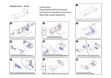
20
SEE FIG. 13
1. Open the burner access door. Remove door and put in
a safe place.
2. Remove 4 inner panel securing screws and remove
panel.
3 Remove the 3 plinth securing screws and remove
plinth.
SEE FIG. 16
1. Make electrical connections to terminal strip as wiring
diagram (See Fig. 14).
2. Always route cables from the external power supply
and control systems away from hot surfaces.
SEE FIG 15
1. Bring the sensing phial of the fire valve through the
grommet in the right hand side panel and locate in the
clips provided.
2. Before connecting the flexible oil pipe to the pump
inlet, open the stop valve slowly and run off some of
the oil into a receptacle to establish an air free supply
and clean supply to the pump. Make the connection
onto the oil pump tight and leave valve open.
3. Ensure that the fire valve is routed to allow free
removal of the twin burner assembly.
Commissioning Instructions
Fig. 13 DESN 511998
DESN 511577
DESN 512000
Fig. 14
Fig. 15
BURNER ACCESS
OIL PUMP
ELECTRICAL CONNECTION
TERMINAL STRIP
/