RKI Instruments Diffusion EAGLE Owner's manual
- Category
- Carbon monoxide (CO) detectors
- Type
- Owner's manual

RKI Instruments, Inc. • 33248 Central Ave, Union City, CA 94587
4 • (510) 441-5656
Instruction Manual
Standard Diffusion Eagle Series
Portable Multi-Gas Detector
Part Number: 71-0042RK
Revision: 0
Released: 2/11/03

Warrant
y
Diffusion Ea
g
le Instruction Manual
Warranty
RKI Instruments, Inc., warrants gas alarm equipment manufactured by RKI
and sold by RKI to be free from defects in materials and workmanship for a
period of one year from date of shipment from RKI Instruments, Inc. Any
parts found defective within that period will be repaired or replaced, at our
option, free of charge. This warranty does not apply to items that are subject
to deterioration or consumption in normal service, and which must be
cleaned, repaired, or replaced routinely. Those items include, but are not
limited to the following:
This warranty is voided by mechanical damage, misuse, alteration, rough
handling, or repairs not in accordance with the operator’s manual. This
warranty indicates the full extent of our liability. We are not responsible for
removal or replacement costs, local repair costs, transportation costs, or
contingent expenses incurred without our prior approval.
T
HIS
WARRANTY
IS
IN
LIEU
OF
ANY
OTHER
WARRANTIES
AND
REPRESENTATIONS
,
EXPRESSED
OR
IMPLIED
,
AND
ALL
OTHER
OBLIGATIONS
OR
LIABILITIES
ON
THE
PART
OF
RKI I
NSTRUMENTS
, I
NC
.,
INCLUDING
BUT
NOT
LIMITED
TO
THE
WARRANTY
OF
MERCHANTABILITY
OR
FITNESS
FOR
A
PARTICULAR
PURPOSE
. I
N
NO
EVENT
SHALL
RKI I
NSTRUMENTS
, I
NC
.,
BE
LIABLE
FOR
INDIRECT
,
INCIDENTAL
,
OR
CONSEQUENTIAL
LOSS
OR
DAMAGE
OF
ANY
KIND
CONNECTED
WITH
THE
USE
OF
ITS
PRODUCTS
OR
FAILURE
OF
ITS
PRODUCTS
TO
FUNCTION
OR
OPERATE
PROPERLY
.
This warranty covers instruments and parts sold to end users by authorized
distributors, dealers, and representatives of RKI Instruments, Inc.
We do not assume indemnification for any accident or damage caused by the
operation of this gas monitor. Our warranty is limited to replacement of parts
or our complete goods.
absorbent cartridges filter elements
pump diaphragms and valves batteries
lamp bulbs and fuses

Diffusion Ea
g
le Instruction Manual Table of Contents
Table of Contents
Introduction. . . . . . . . . . . . . . . . . . . . . . . . . . . . . . . . . . . . . . . . . . . . . . . .1
Overview . . . . . . . . . . . . . . . . . . . . . . . . . . . . . . . . . . . . . . . . . . . . . . . . . . . . 1
About this Manual . . . . . . . . . . . . . . . . . . . . . . . . . . . . . . . . . . . . . . . . . . . . . 2
Specifications . . . . . . . . . . . . . . . . . . . . . . . . . . . . . . . . . . . . . . . . . . . . . .3
Description: Eagle and Remote Detector . . . . . . . . . . . . . . . . . . . . . . . . .5
Eagle Case . . . . . . . . . . . . . . . . . . . . . . . . . . . . . . . . . . . . . . . . . . . . . . . . . . . 5
Control Panel . . . . . . . . . . . . . . . . . . . . . . . . . . . . . . . . . . . . . . . . . . . . . . . . . 5
Buttons. . . . . . . . . . . . . . . . . . . . . . . . . . . . . . . . . . . . . . . . . . . . . . . . . . . . . . 5
Alarm Lights . . . . . . . . . . . . . . . . . . . . . . . . . . . . . . . . . . . . . . . . . . . . . . . . . 6
Battery Charger Connector . . . . . . . . . . . . . . . . . . . . . . . . . . . . . . . . . . . . . . 6
Interface Port . . . . . . . . . . . . . . . . . . . . . . . . . . . . . . . . . . . . . . . . . . . . . . . . . 6
Buzzer . . . . . . . . . . . . . . . . . . . . . . . . . . . . . . . . . . . . . . . . . . . . . . . . . . . . . . 6
Circuit Boards . . . . . . . . . . . . . . . . . . . . . . . . . . . . . . . . . . . . . . . . . . . . . . . . 6
Methane Elimination Switch . . . . . . . . . . . . . . . . . . . . . . . . . . . . . . . . . . . . . 7
CAL/SETUP Switch . . . . . . . . . . . . . . . . . . . . . . . . . . . . . . . . . . . . . . . . . . . 7
Remote Detector . . . . . . . . . . . . . . . . . . . . . . . . . . . . . . . . . . . . . . . . . . . . . . 7
Operation. . . . . . . . . . . . . . . . . . . . . . . . . . . . . . . . . . . . . . . . . . . . . . . . .11
Starting Up the Eagle. . . . . . . . . . . . . . . . . . . . . . . . . . . . . . . . . . . . . . . . . . 11
Normal Operation . . . . . . . . . . . . . . . . . . . . . . . . . . . . . . . . . . . . . . . . . . . . 16
Monitoring Combustible Gas in the PPM Range. . . . . . . . . . . . . . . . . . . . . 16
Monitoring Combustible Gases Other than Methane. . . . . . . . . . . . . . . . . . 17
Setting User Access . . . . . . . . . . . . . . . . . . . . . . . . . . . . . . . . . . . . . . . . . . . 18
Turning Off the Eagle . . . . . . . . . . . . . . . . . . . . . . . . . . . . . . . . . . . . . . . . . 18
Alarms. . . . . . . . . . . . . . . . . . . . . . . . . . . . . . . . . . . . . . . . . . . . . . . . . . .19
Alarm Indications. . . . . . . . . . . . . . . . . . . . . . . . . . . . . . . . . . . . . . . . . . . . . 19
Resetting Gas Alarms. . . . . . . . . . . . . . . . . . . . . . . . . . . . . . . . . . . . . . . . . . 22

Table of Contents Diffusion Ea
g
le Instruction Manual
Display Mode . . . . . . . . . . . . . . . . . . . . . . . . . . . . . . . . . . . . . . . . . . . . .23
User and Station ID Screen . . . . . . . . . . . . . . . . . . . . . . . . . . . . . . . . . . . . . 23
Peak Screen . . . . . . . . . . . . . . . . . . . . . . . . . . . . . . . . . . . . . . . . . . . . . . . . . 24
Elapsed Time Screen . . . . . . . . . . . . . . . . . . . . . . . . . . . . . . . . . . . . . . . . . . 24
TWA/STEL Screen . . . . . . . . . . . . . . . . . . . . . . . . . . . . . . . . . . . . . . . . . . . 25
Battery Voltage Screen. . . . . . . . . . . . . . . . . . . . . . . . . . . . . . . . . . . . . . . . . 25
Date/Time Screen. . . . . . . . . . . . . . . . . . . . . . . . . . . . . . . . . . . . . . . . . . . . . 25
Clear Data Logger Screens . . . . . . . . . . . . . . . . . . . . . . . . . . . . . . . . . . . . . 26
Remaining Log Time Screen . . . . . . . . . . . . . . . . . . . . . . . . . . . . . . . . . . . . 26
Setup Mode. . . . . . . . . . . . . . . . . . . . . . . . . . . . . . . . . . . . . . . . . . . . . . .27
Tips for Using Setup Mode . . . . . . . . . . . . . . . . . . . . . . . . . . . . . . . . . . . . . 28
Entering Setup Mode . . . . . . . . . . . . . . . . . . . . . . . . . . . . . . . . . . . . . . . . . . 28
Updating the Battery Type Setting. . . . . . . . . . . . . . . . . . . . . . . . . . . . . . . . 28
Updating Channel Settings. . . . . . . . . . . . . . . . . . . . . . . . . . . . . . . . . . . . . . 29
Updating the Combustible Gas Channel’s Units of Measure. . . . . . . . . . . . 36
Updating the Alarm Point Settings. . . . . . . . . . . . . . . . . . . . . . . . . . . . . . . . 36
Updating the Eagle’s Serial Number . . . . . . . . . . . . . . . . . . . . . . . . . . . . . . 37
Updating the Lunch Break Setting. . . . . . . . . . . . . . . . . . . . . . . . . . . . . . . . 38
Updating the Alarm Latching Setting . . . . . . . . . . . . . . . . . . . . . . . . . . . . . 38
Updating the Alarm Silence Setting. . . . . . . . . . . . . . . . . . . . . . . . . . . . . . . 39
Turning the User ID Function On or Off . . . . . . . . . . . . . . . . . . . . . . . . . . . 39
Updating the Auto Calibration Settings. . . . . . . . . . . . . . . . . . . . . . . . . . . . 40
Updating the Back Light Setting . . . . . . . . . . . . . . . . . . . . . . . . . . . . . . . . . 41
Turning the Auto Fresh Air Function On or Off . . . . . . . . . . . . . . . . . . . . . 41
Updating the Interval Time Setting (data log option) . . . . . . . . . . . . . . . . . 42
Updating the Log Data Over Write Setting (data log option) . . . . . . . . . . . 42
Updating the Time Calibration Setting (data log option). . . . . . . . . . . . . . . 43
Updating the Date and Time Settings (data log option). . . . . . . . . . . . . . . . 43
Updating the Zero Following Settings. . . . . . . . . . . . . . . . . . . . . . . . . . . . . 43
Updating the Confirmation Beep Setting. . . . . . . . . . . . . . . . . . . . . . . . . . . 44
Returning to Default Settings. . . . . . . . . . . . . . . . . . . . . . . . . . . . . . . . . . . . 44

Diffusion Ea
g
le Instruction Manual Table of Contents
Calibration. . . . . . . . . . . . . . . . . . . . . . . . . . . . . . . . . . . . . . . . . . . . . . . .46
Calibration Supplies and Equipment . . . . . . . . . . . . . . . . . . . . . . . . . . . . . . 46
Preparing for Calibration . . . . . . . . . . . . . . . . . . . . . . . . . . . . . . . . . . . . . . . 46
Calibrating the Eagle . . . . . . . . . . . . . . . . . . . . . . . . . . . . . . . . . . . . . . . . . . 47
Maintenance . . . . . . . . . . . . . . . . . . . . . . . . . . . . . . . . . . . . . . . . . . . . . .51
Displaying the Battery Voltage . . . . . . . . . . . . . . . . . . . . . . . . . . . . . . . . . . 51
Replacing the Alkaline Batteries . . . . . . . . . . . . . . . . . . . . . . . . . . . . . . . . . 51
Recharging Ni-Cd Batteries. . . . . . . . . . . . . . . . . . . . . . . . . . . . . . . . . . . . . 51
Replacing Ni-Cd Batteries. . . . . . . . . . . . . . . . . . . . . . . . . . . . . . . . . . . . . . 52
Replacing Sensors . . . . . . . . . . . . . . . . . . . . . . . . . . . . . . . . . . . . . . . . . . . . 52
Appendix A: Parts List . . . . . . . . . . . . . . . . . . . . . . . . . . . . . . . . . . . . . .57
Appendix B: Methane Elimination. . . . . . . . . . . . . . . . . . . . . . . . . . . . .58
Appendix C: Installing the Data Logger Board . . . . . . . . . . . . . . . . . . .60

Diffusion Ea
g
le Instruction Manual Introduction • 1
Introduction
Overview
The RKI Standard Diffusion Eagle is the most advanced portable gas
detection system available. The Eagle is built for rugged reliability and ease
of use and includes the latest innovations in gas detection technology:
• Simultaneous detection of one-to-four gases. Standard target gases
include combustible gas (% LEL and ppm), oxygen deficiency, carbon
monoxide, and hydrogen sulfide.
• Dot-matrix liquid crystal display (LCD) for complete, understandable
information at a glance.
• Microprocessor control for all functions, including data logging (the Data
Logger Board is optional) and user-adjustable alarms.
•Visible and audible alarms for hazardous conditions and malfunctions.
• CSA classified. Intrinsic safety for Class I, Division I, Groups A, B, C,
and D hazardous atmospheres.
•Tough case with a balanced, light-weight design.
• Optional Data Logger board.
• Remote four-gas sensor detector box.
• Standard twenty-foot extender cable; fifty-foot extender cable optional.
• Recharging cable.
WARNING: The Eagle detects a combination of combustible gas, oxygen
deficiency, hydrogen sulfide and carbon monoxide. Users must
follow the instructions and warnings in this manual to assure
proper and safe operation of the Eagle.

2 • Introduction Diffusion Ea
g
le Instruction Manual
About this Manual
This manual is intended for use with the Eagle portable gas detection system.
Examples used in this manual cover combustible gas, oxygen, carbon
monoxide, and hydrogen sulfide. This manual is organized as follows:
• The main section of the manual describes the Eagle’s specifications and
internal and external components. It also describes the operation,
calibration, and maintenance of the Eagle.
• Appendix A lists part numbers for the Eagle’s replacement parts and
accessories.
• Appendix B describes the Eagle’s methane elimination feature.
• Appendix C describes the procedure to install the Eagle’s optional Data
Logger board.

Diffusion Ea
g
le Instruction Manual Specifications • 3
Specifications
Table 1 lists physical and environmental specifications for the Eagle. Table 2
lists specifications for the Eagle’s standard sensors.
Table 1: Eagle Specifications
Target Gases Combustible gas; Oxygen (O
2
),
Carbon monoxide (CO); Hydrogen sulfide (H
2
S)
Case High-impact polycarbonate-polyester blend
Safety/Regulatory
1
CSA/NTRL classified intrinsically safe
(Class I, Division 1, Groups A, B, C, and D)
Dimensions 10.5 in. x 5.9 in. x 7.0 in. (26.7 cm x 15.0 cm x 17.8 cm)
Weight 4.4 lbs. (1.99 kg)
Power Four D-size batteries (alkaline or Ni-Cd)
Continuous Operating
Hours
Alkaline: 36 hours (minimum)
Ni-Cd: 20 hours (minimum)
2
Operating Temperature 14°F to 104°F (-10°C to 40°C)
Humidity 0 to 95% (non-condensing)
Standard Accessories Remote Detector with four gas sensors; 50-foot extender cable;
four D-size alkaline batteries
Optional Accessories Remote alarm; Data Logger board; data logging cable; Ni-Cd
batteries; battery charger (115 VAC); continuous operation
adapter (115 VAC or 12 VDC);
1 Consult RKI Instruments, Inc., for regulatory classifications of versions other than the four standard gases.
2 Based on RKI part number 49-1240RK.

4 • Specifications Diffusion Ea
g
le Instruction Manual
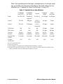
Table 2 lists specifications for the Eagle’s standard sensors. Your Eagle model
may not include all of the sensors listed below. The alarm settings are user-
adjustable (see “Updating the Alarm Point Settings” on page 36.)
Table 2: Standard Sensor Specifications
Combustible
Gas (%LEL
1
)
Combustible
Gas (PPM
2
)
Oxygen
Hydrogen
Sulfide
Carbon
Monoxide
Range 0 to 100% LEL Depends on
target gas
4
0 to 40% O
2
0 to 100 ppm 0 to 500 ppm
Alarm 1 10% LEL 5000 ppm 19.5% O
2
(decreasing)
10.0 ppm 25 ppm
Alarm 2 50% LEL 25,000 ppm 23.5% O
2
(increasing)
30.0 ppm 50 ppm
TWA Alarm N/A N/A N/A 10.0 ppm 25 ppm
STEL Alarm N/A N/A N/A 15.0 ppm 400 ppm
Detection
Principle
Catalytic
combustion
Catalytic
combustion
Electro-
chemical
Electro-
chemical
Electro-
chemical
Response Time
(to 90%)
15 seconds 15 seconds 20 seconds 40 seconds 55 seconds
Accuracy
(of full-scale)
± 5% ± 5% ± 5% ± 5% ± 5%
1 LEL (Lower Explosive Limit)
2 PPM (Parts Per Million)
3 Alarms settings are user adjustable. See “Updating the Alarm Point Settings” on page 36.
4 The PPM range represents the same range as 0 to 100% LEL for that gas. For example, 100% LEL for methane = 5% by
volume = 50,000 PPM. Therefore, the PPM range for methane is 0 to 50,000.

Diffusion Ea
g
le Instruction Manual Description: Ea
g
le and Remote Detector • 5
Description: Eagle and Remote Detector
Eagle Case
The Eagle has a plastic case with a full-sized handle. The high-visibility case
is shielded to reduce radio frequency and electromagnetic interference (RFI/
EMI). The system is light-weight and balanced, which makes the Eagle easy
to carry and use for extended periods. A foam rubber gasket between the top
and bottom case components is water- and dust-resistant. You can set the case
into 2.5 in. of water without damage.
Control Panel
The control panel is at the top of the Eagle. The touch-pad buttons reduce the
risk of accidental activation. The dot matrix display simultaneously shows the
gas reading for all installed sensors. The display also shows information for
each of the Eagle’s program modes.
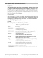
Buttons
The control panel includes the following six buttons.
Table 3: Eagle Button Functions
Button Function(s)
POWER/ENTER • turns the Eagle on and off.
• used during setup and calibration.
RESET/SILENCE silences and resets audible alarm if the Eagle is programmed for
latching alarms and the Alarm Silence option is on
1
DISP/ADJ • activates display modes
• enters instructions into the Eagle’s microprocessor
LEL/PPM switches combustible gas detection ranges between %LEL (lower
explosive limit) and PPM (parts per million)
2
AIR/▲
• activates the demand-zero function (automatically adjusts the Eagle
in fresh-air conditions)
• scrolls through the display and settings modes
SHIFT/
▼
• scrolls through the calibration and settings modes
• enters instructions into the Eagle’s microprocessor
1 The Eagle’s alarms are user-adjustable. See “Setup Mode” on page 27.
2 The LEL range is commonly used for safety applications; the PPM range can be used for environmental or other
special applications.

6 • Description: Ea
g
le and Remote Detector Diffusion Ea
g
le Instruction Manual
Alarm Lights
Two ultra-bright, red, light-emitting diodes (LEDs) provide visual alarms for
gas concentrations and malfunctions. They are mounted on the top rear of the
case for greatest visibility.
Battery Charger Connector
The battery charger connector is mounted on the top right rear of the case.
The external battery charger connects to this connector to recharge nickel-
cadmium (Ni-Cd) batteries. The continuous operation adapter also connects
to the battery charger connector.
Interface Port
The interface port is for optional data logging or for the remote buzzer. The
port is mounted on the top left rear of the case. When the data logging option
is installed, the Eagle records gas concentrations at programmed intervals and
stores data on gas detected. You can download these measurements through
the interface port to a PC-compatible computer for use in data analysis
programs. Data retrieval requires the Eagle Data Down Loader Kit (with PC
connection cable and software).
The optional remote buzzer or remote buzzer/strobe also connect to the
interface port, and are for use in applications in which a remote alarm
indication is required.
Buzzer
A solid-state electronic buzzer is mounted inside the top of the case. The
buzzer sounds for gas alarms, malfunction, low battery voltage, and as an
indicator during use of the Eagle’s many display and adjustment options.
Circuit Boards
The Eagle circuit boards analyze, record, control, store, and display the
information collected.
The analog PCB is mounted perpendicular to the base of the instrument case.
The sensor leads connect to the analog PCB.
The main PCB is mounted in the top half of the case. It includes the methane
elimination and CAL/SETUP switches.
CAUTION: The circuit boards should be serviced only by authorized
repair personnel.

Diffusion Ea
g
le Instruction Manual Description: Ea
g
le and Remote Detector • 7
Methane Elimination Switch
The methane elimination switch (SW1) is mounted near the top right corner
of the main PCB.
For applications where methane is an interfering gas, you can set the methane
elimination switch to eliminate most response to methane (see “Appendix B:
Methane Elimination” on page 58). An external methane elimination switch
is available as an option.
CAL/SETUP Switch
The CAL/SETUP switch (SW2) is mounted near the middle left edge of the
main PCB. This switch controls the Eagle functions available to the user by
disabling the SHIFT/
▼ button. Without the use of this button, the user is
unable to enter Calibration or Setup mode. (Display mode is available with
either switch setting.) See “Setting User Access” on page 18 to change the
switch setting.
Remote Detector
This section describes the Eagle’s Remote Detector. The Remote Detector is
used to detect combustible gas, oxygen, carbon monoxide, and hydrogen
sulfide using four sensors mounted inside a durable plastic case. These
sensors are connected to a printed circuit board, which is also located inside
the case. The Remote Detector includes a buzzer that sounds for gas alarms
and sensor malfunction. The Remote Detector can be connected either
directly to the Eagle, or it can be connected to the Eagle via a 50-foot
extender cable.
Case
The Remote Detector has a durable plastic case with a removable lid secured
by four screws. A removable rubber o-ring gasket mounted in the lid helps
protect the sensors, buzzer, and PCB from water, dust, and the corrosive
effects of gas and vapor.

8 • Description: Ea
g
le and Remote Detector Diffusion Ea
g
le Instruction Manual
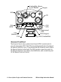
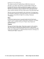
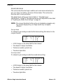
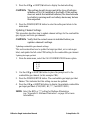
Interconnect Circuit Board
The Remote Detector has a printed circuit board (PCB) located inside its
case, the interconnect PCB. The PCB is mounted perpendicular to the base of
the Remote Detector’s case. It is positioned near the connector used to attach
the Remote Detector to the Eagle. The PCB provides connection points for
the Remote Detector’s four sensors, described below, and a connection point
for the Remote Detector’s buzzer.
Interconnect
PCB
Oxygen
CO
CN6
CN3 (Combustible)
CN1
(CO)
CN4
(H2S)
CN5
(Buzzer)
H2S
CN2 (Oxygen)
Combustible, Shown
w/out Bracket

Diffusion Ea
g
le Instruction Manual Description: Ea
g
le and Remote Detector • 9
Sensors
Under normal conditions, the Eagle’s standard sensors have an operating life
of approximately two years. To replace the sensors, open the case by
unscrewing the four screws that secure the lid to the case. (See “Replacing
Sensors” on page 52 for more details.)
Combustible gas sensor
The combustible gas (LEL) sensor is mounted with the flame arrestor
extending outside the case to allow the ambient air to diffuse into the sensor.
Five pins extend from the top of the sensor. The sensor cable connects to the
pins on one end and terminates in a four-position connector, which plugs into
the COMB (CN3) socket on the interconnect printed circuit board (PCB)
inside the Remote Detector.
The LEL sensor detects combustible gas and vapors in the atmosphere with a
catalytic platinum element. The reaction of gas with oxygen on the catalyst
causes a change in the resistance of the element, which is converted by the
Eagle into a reading of combustible gas concentration.
Oxygen sensor
The oxygen (O
2
) sensor is mounted with its face behind a perforated hole
pattern covered by a hydrophobic membrane to allow the ambient air to
diffuse into the sensor. A multi-pin plug connects the O
2
sensor to the OXY
(CN2) socket on the interconnect PCB. This socket sticks up higher than the
rest.
The O
2
sensor is an electrochemical cell, which reacts to the oxygen in the
atmosphere and produces a voltage proportional to the oxygen concentration.
This voltage is converted by the Eagle into a reading of oxygen
concentration.

10 • Description: Ea
g
le and Remote Detector Diffusion Ea
g
le Instruction Manual
Standard toxics (CO and H2S) sensors
The carbon monoxide (CO) and hydrogen sulfide (H
2
S) sensors are
physically very similar. They both have cylindrical bodies and they are
mounted with their faces behind a perforated hole pattern covered by a
hydrophobic membrane to allow the ambient air to diffuse into the sensors.
The CO sensor connector connects to the CO (CN1) socket and the H
2
S
sensor connector connects to the H
2
S (CN4) socket on the interconnect PCB.
The toxics sensors are electrochemical cells, which react to the target gas in
the atmosphere, producing a current proportional to the concentration of gas.
The current is converted by the Eagle into a reading of target gas
concentration.
Buzzer
A solid-state electronic buzzer is mounted inside the lid of the Remote
Detector’s case. The buzzer sounds for gas alarms, malfunction, low battery
voltage, and as an indicator during use of Eagle’s many display and
adjustment options.
Connector
The Remote Detector has a single, 18-pin male connector with a retaining
ring. The connector is attached to the Remote Detector’s case by three
screws. The connector allows the Remote Detector to be attached to the Eagle
in two ways, as stated above. (To attach the Remote Detector to the Eagle, see
“Starting Up the Eagle” on page 11.)

Diffusion Ea
g
le Instruction Manual Operation • 11
Operation
The Eagle has four operating modes: normal operating mode, display mode,
setup mode, and calibration mode. This section describes the Eagle in normal
operating mode. It includes procedures to start up the Eagle, set various
detection options for the combustible gas channel, and shut down the Eagle.
NOTE: The screens illustrated in this section are intended as examples only.
The screens displayed by your Eagle model may be slightly
different.
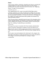
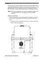
Starting Up the Eagle
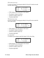
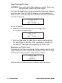
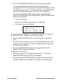
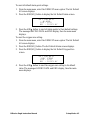
1. Connect the Remote Detector either directly to the Eagle or use the 20-
foot or 50-foot extender cable. To make this connection, follow these
steps:
• Find the connector for the Remote Detector on the front end of the
Eagle’s bottom case assembly.
Eagle
Connector

12 • Operation Diffusion Ea
g
le Instruction Manual
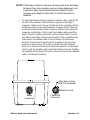
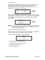
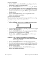
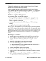
•To attach the Remote Detector directly to the Eagle, position the
Remote Detector coupling in the unlocked position as shown below.
Then line up the tab inside the connector on the Remote Detector
with the notch inside the connector on the Eagle. Gently push the
Remote Detector toward the Eagle. Turn the coupling clockwise on
the connector of the Remote Detector to secure the Remote Detector
to the Eagle’s bottom case assembly.
Locked Position
Locked Position
Coupling shown in
Unlocked Position,
Counterclockwise to Locked

Diffusion Ea
g
le Instruction Manual Operation • 13
NOTE: If the Remote detector has been disconnected from the Eagle
for more than a few minutes, such as during shipment, wait
15 minutes after connecting the Remote detector before
turning on the Eagle to allow the CO and H
2
S sensors to
stabilize.
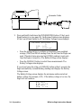
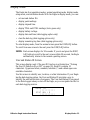
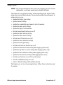
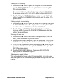
•To attach the Remote Detector using an extender cable, carefully fit
the end of the extender cable that has a coupling to the Eagle’s
connector. Make sure to line up the tabs inside the coupling with the
matching notches in the cable connector as shown below. Then line
up the tab on the extender cable connector with the notch inside the
connector on the Eagle. Gently push the extender cable toward the
Eagle. Turn the coupling clockwise on the extender cable to secure
the cable to the Eagle’s bottom case assembly. Next, carefully fit the
other end of the extender cable to the connector on the Remote
Detector. Position the Remote Detector coupling in the unlocked
position as shown above. Then line up the tab inside the Remote
Detector connector with the notch inside the connector on the Eagle.
Gently push the extender cable toward the Remote Detector. Tighten
the coupling on the Remote Detector connector to secure the extender
cable to the Remote Detector.
Rotate to Lock
Align Keys in Key
Way For Assembly
Cable End
Connector
Eagle
Connector

14 • Operation Diffusion Ea
g
le Instruction Manual
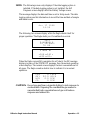
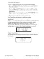
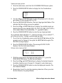
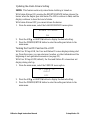
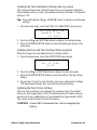
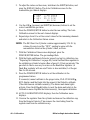
2. Press and briefly hold down the POWER/ENTER button. If the Lunch
Break feature is on (see page 38), the Resume Datalog screen displays.
(If the Lunch Break feature is off, the Battery Voltage screen displays.)
• Press the AIR/
▲ button to continue accumulating time-weighted
average (TWA) and PEAK readings from the last time the Eagle was
used. (The short-term exposure limit [STEL] reading is reset each
time the Eagle is turned on.) The Battery Voltage screen displays.
• Press the DISP/ADJ button to restart these measurements. The
Battery Voltage screen displays.
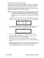
If you do not press the
AIR/▲ or DISP/ADJ button within 5 seconds, the
Eagle automatically resumes datalog readings and displays the Battery
Voltage screen.
The Battery Voltage screen displays the minimum usable and actual
battery voltage (for example, 6.0V). If the battery voltage is too low, the
Eagle will not continue.
E
S
UDT
N
I
YE
S
A
A
A:
L
R
S
I
D
OG
R
M
E
?
O
P
:
5
L
AY
Extender Cable
BA
T
TERY
MIN
.4
.
5V
BA
T
TERY
60V.
NO
W

Diffusion Ea
g
le Instruction Manual Operation • 15
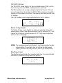
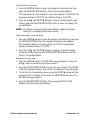
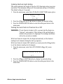
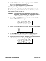
NOTE: The following screen only displays if the data logging option is
installed. If the data logging option is not installed, the Self
Diagnosis screen displays after the Battery Voltage screen.
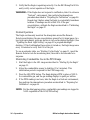
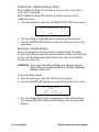
This message displays the date and time as set in Setup mode. The data
logging option uses this information to record the time and date of sample
and alarm events.
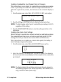
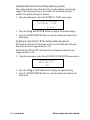
The following two screens display while the Eagle checks itself for
proper operation. The Eagle alerts you if a malfunction occurs.
When the Eagle successfully completes its self check, the OK message
displays in place of the STAND BY message, then the normal operating
screen displays. The normal screen displays fresh-air concentrations for
all gases. The Eagle sounds a double tone to indicate it is in normal
operation.
CAUTION: Do not use gas from a cigarette lighter to test response to
combustibles. Exposing the combustible gas sensor to
uncontrolled high concentrations of gas will reduce
response and sensor life.
PA
17 1
4
:
R
998
130
S
GN
S
S
E
I
S
C
O
DIA O
EL
F
0
NDS
T
O
G
O
ST
A
ND BY
CH
4
><O Y
C
>
O
H
2
S
<X
>
<<
>
1
CH
4
OY
C
O
H
2
S
X
2
0.9
0
0
0.0
L
V
P
P
P
P
M
M
E
O
L
L
%
%
Page is loading ...
Page is loading ...
Page is loading ...
Page is loading ...
Page is loading ...
Page is loading ...
Page is loading ...
Page is loading ...
Page is loading ...
Page is loading ...
Page is loading ...
Page is loading ...
Page is loading ...
Page is loading ...
Page is loading ...
Page is loading ...
Page is loading ...
Page is loading ...
Page is loading ...
Page is loading ...
Page is loading ...
Page is loading ...
Page is loading ...
Page is loading ...
Page is loading ...
Page is loading ...
Page is loading ...
Page is loading ...
Page is loading ...
Page is loading ...
Page is loading ...
Page is loading ...
Page is loading ...
Page is loading ...
Page is loading ...
Page is loading ...
Page is loading ...
Page is loading ...
Page is loading ...
Page is loading ...
Page is loading ...
Page is loading ...
Page is loading ...
Page is loading ...
Page is loading ...
Page is loading ...
-
 1
1
-
 2
2
-
 3
3
-
 4
4
-
 5
5
-
 6
6
-
 7
7
-
 8
8
-
 9
9
-
 10
10
-
 11
11
-
 12
12
-
 13
13
-
 14
14
-
 15
15
-
 16
16
-
 17
17
-
 18
18
-
 19
19
-
 20
20
-
 21
21
-
 22
22
-
 23
23
-
 24
24
-
 25
25
-
 26
26
-
 27
27
-
 28
28
-
 29
29
-
 30
30
-
 31
31
-
 32
32
-
 33
33
-
 34
34
-
 35
35
-
 36
36
-
 37
37
-
 38
38
-
 39
39
-
 40
40
-
 41
41
-
 42
42
-
 43
43
-
 44
44
-
 45
45
-
 46
46
-
 47
47
-
 48
48
-
 49
49
-
 50
50
-
 51
51
-
 52
52
-
 53
53
-
 54
54
-
 55
55
-
 56
56
-
 57
57
-
 58
58
-
 59
59
-
 60
60
-
 61
61
-
 62
62
-
 63
63
-
 64
64
-
 65
65
-
 66
66


RKI Instruments Diffusion EAGLE Owner's manual
- Category
- Carbon monoxide (CO) detectors
- Type
- Owner's manual
Ask a question and I''ll find the answer in the document
Finding information in a document is now easier with AI
Related papers
-
RKI Instruments EAGLE 1 Inert Gas Testing Eagle Owner's manual
-
-
-
-
-
-
-
-
-
Other documents
-
 Eagle Home Products Eagle Series User manual
-
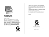 Quest Products Quest SafeCheck 200 O2/LEL Gas Monitor 200 User manual
-
 Henan Oceanus Import & Export OC-F08 Operating instructions
-
 Gas Clip -MGC-S Multi Gas Clip Simple User guide
-
 CPS Products LSCG Quick start guide
-
EAGLE PEAK GHS22-GRN-AZ User manual
-
EAGLE PEAK Lean To Greenhouse 6.6 x 3.3 x 6.9 ft User manual
-
Gas Clip Technologies MGC User guide
-
-
 New Cosmos Electric KS-7D User manual


