Page is loading ...

iConverter
®
2GXT
Standalone Module User Manual
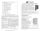
Product Overview
The iConverter 2GXT is a standalone, unmanaged media converter with two 10/100/1000 RJ-45
copper ports and two Small Form Pluggable (SFP) ber ports. The 2GXT can be deployed as a dual-
channel media converter that provides two independent copper-to-ber converters in one compact
module, or deployed as a four-port switch with dual ber ports that can be congured to provide 1:1
uplink protection with less than 50ms switchover.
The 2GXT supports both 100BASE-X and 1000BASE-X SFPs to provide exible connectivity to Fast
Ethernet or Gigabit networks.
Installation Procedure
1) Congure DIP-switches
2) Install Standalone Module and Connect Cables
3) Verify Operation
1) CONFIGURE DIP-SWITCHES
DIP-SWITCH BANK 1
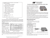
The location of the DIP-switches is shown in Figure 1. The functions of DIP-switch Bank 1 are
outlined in Figure 2.
Figure 1: DIP-switch Locations
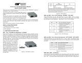
Switch Function DOWN (Default) UP
SW3
Operational Modes See Figure 3
SW4
SW5 Pause Off On
SW6 Link Propagate Fiber to Copper Link Segment
Link Propagate Fiber to Copper
P1 to P3 and P2 to P4
SW7 Link Propagate Copper to Fiber Link Segment
Link Propagate Copper to Fiber
P3 to P1 and P4 to P2
SW8 L2CP Forward Off (Discard) On (Forward)
Figure 2: DIP-switch BANK 1 Denitions
Page 1
SW3 SW4 Mode
Down Down 4-Port Switch Mode
Down Up Dual Media Converter Mode
Up Down Switch with Redundant Fiber Mode - no return to Port 1
Up Up Switch with Redundant Fiber Mode - return to Port 1
Figure 3: Operational Modes
SW3 and SW4: Operational Modes
4-Port Switch Mode
When SW3 and SW4 are in the default DOWN position, the module operates as a 4-Port Layer 2
Ethernet switch.
Dual Media Converter Mode
When SW3 is in the DOWN position and SW4 is in the UP position, the module operates as two
separate and independent copper-to-ber media converters, with P1 and P3 as one media converter,
and P2 and P4 as the other media converter.
Redundant Fiber Mode
When SW3 is in the UP position, the module operates as a 4-Port Layer 2 Ethernet switch with the ber
ports congured as redundant links. When congured for link redundancy, the module will transmit
and receive trafc on the primary port (Port 1) and no trafc on the backup port (Port 2). When a
ber failure occurs on the primary port, the device will switch over to the backup port within 50msec.
When SW4 is in the DOWN position, the module will remain on the backup port (Port 2) even when a
stable connection has been established on Port 1. When SW4 is in the UP position, the module will
switch back to the primary port (Port 1) once a stable connection has been established.
SW5: Pause
The Pause DIP-switch sets the ow control functionality for all ports on the module, including pause
mode advertisement, pause functionality, and half duplex back pressure. When the DIP-switch is in
the Pause UP position, ow control functionality is enabled. When this DIP-switch is in the Pause
DOWN position (factory default), ow control functionality is disabled.
If Pause is enabled and the port is in half duplex, then half duplex ow control is enabled. When a port
is in half duplex ow control it generates a back pressure signal when internal buffer resources are low.
If Pause is enabled and the port is in full duplex, then full duplex ow control is enabled. When a port
is in full duplex ow control and internal buffering resources are low, a pause frame is generated to
slow down the trafc ow to the port.
SW6 and SW7: Link Modes
These DIP-switches congure the link mode settings. It is recommended to have link modes DOWN
position (default) during the initial installation. After the circuit has been tested and operational,
congure the module for the desired mode. Link Modes are only valid when the module is operating
in the Dual Media Converter mode.
Link Segment
In Link Segment mode, all ports operate independently. A loss of a receive link signal will only affect
the port detecting the loss of signal. All the other ports will continue to generate a link signal.
Link Propagate
In Link Propagate mode, faults are propagated based on the port notation. Port 1 to Port 3 notation
indicates the direction the loss of link signal will propagate. A loss of receive link on Port 1 causes
Port 3 to drop its link due to the propagated state (Port 1 to Port 3).
SW8: L2CP Forward
When this DIP-switch is in the default Down position, the module will discard all L2CP frames. When
the DIP-switch is in the Up position, the module will forward all L2CP frames.
Page 2

Page 3
DIP-SWITCH BANK 2
The functions of DIP-switch Bank 2 are outlined in Figure 4.
Switch Function DOWN (Default) UP
SW1 Port 1 Speed Auto 100
SW2 Port 2 Speed Auto 100
SW3 Port 3 Negotiation Auto Negotiation Manual (Forced)
SW4 Port 3 Speed 100 10
SW5 Port 3 Duplex Full Duplex (FDX) Half Duplex (HDX)
SW6 Port 4 Negotiation Auto Negotiation Manual (Forced)
SW7 Port 4 Speed 100 10
SW8 Port 4 Duplex Full Duplex(FDX) Half Duplex (HDX)
Figure 4: DIP-switch Bank 2 Denitions
SW1 and SW2: SFP Port Speed
These DIP-switches congure the speed of the transceivers installed in the SFP ports. If these
DIP-switches are in the DOWN (default) position, the ports will detect the data rate of the transceivers
installed and operate at 100M or 1G accordingly. If these DIP-switches are in the UP position, the
ports are expecting a 100M capable transceivers to be installed.
SW3 - SW8: Copper Port Negotiation, Speed and Duplex
See the gure below to congure the port.
Negotiation Speed Duplex RJ-45 Mode of Operation
Auto 10 or 100 FDX or HDX
When set to auto-negotiation the following modes are advertised:
1000FDX, 1000HDX, 100FDX, 100HDX, 10FDX, 10HDX
Manual 100 FDX The RJ-45 port is set to manual and is forced to 100FDX
Manual 100 HDX The RJ-45 port is set to manual and is forced to 100HDX
Manual 10 FDX The RJ-45 port is set to manual and is forced to 10FDX
Manual 10 HDX The RJ-45 port is set to manual and is forced to 10HDX
Figure 5: Copper Port Negotiation, Speed and Duplex Selection
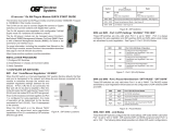
2) INSTALL STANDALONE MODULE AND CONNECT CABLES
Caution: Use proper ESD protection to reduce the risk of damage to your equipment.
a. The 2GXT is available as a standalone module with integrated wall-mount brackets. Attach
the unit to a wall, backboard or other at surfaces. Make sure the unit is placed in a safe, dry
and secure location.
To power the unit using the AC/DC adapter, connect the AC/DC adapter to the AC outlet. Then
connect the barrel plug at the end of the wire on the AC/DC adapter to the 2.5mm DC barrel
connector (center-positive) on the chassis. Conrm that the unit has powered up properly by
checking the power status LED located on the front of the unit.
To power the unit using a DC power source, prepare a power cable using a two conductor
insulated wire (not supplied) with a 14 AWG gauge minimum. Cut the power cable to the length
required. Strip approximately 3/8 of an inch of insulation from the power cable wires. Connect
the power cables to the unit by fastening the stripped ends to the DC power connector. Connect
the power wires to the DC power source (+7 to +60VDC). The Power LED should indicate the
presence of power.
NOTE: If mounting with a safety ground attachment, use the safety ground screw at the
rear of the unit.
b. Insert the SFP ber transceiver into the Port 1 SFP receptacle on the 2GXT.
NOTE: The release latch of the SFP Fiber transceiver must be in the closed position
before insertion.
c. Connect the UTP port via a Category 5 or better cable to a 10BASE-T, 100BASE-TX or
1000BASE-T Ethernet device.
d. Connect an appropriate multimode or single-mode ber cable to the ber port of the installed
module. It is important to ensure that the transmit (TX) is attached to the receive side of the
device at the other end and the receive (RX) is attached to the transmit side. Single-ber (SF)
media converter models operate in pairs. The TX wavelength must match the RX wavelength
at the other end and the RX wavelength must match the TX wavelength at the other end.
3) VERIFY OPERATION
Verify the correct LED is illuminated based on the conguration of the port. Figure 6 indicates the
operation of the port based on the illuminated LEDs.
LED Function
“Legend”
Color OFF State ON/Blinking State
Power
“PWR”
Green No power Module has power
P1/P2 Activity
“100”
Green/
Amber
Port not linked at 100M
Solid Green: Port linked at 100M
Blinking Green (10Hz): Data activity
Blinking Green (1Hz): Port linked and in redundant
standby mode
Solid Amber: Port linked and transceiver has detected a
DDMI alarm
Blinking Amber (10Hz): Data activity and transceiver has
detected an alarm
Blinking Amber (1Hz): Port linked and transceiver has
detected an alarm (redundant standby mode) or Port is
operating at 100M and receiving FEFI
P1/P2 Activity
“1000”
Green/
Amber
Port not linked at 1000M
Solid Green: Port linked at 1000M
Blinking Green (10Hz): Data activity
Blinking Green (1Hz): Port linked and in redundant
standby mode
Solid Amber: Port linked and transceiver has detected a
DDMI alarm
Blinking Amber (10Hz): Data activity and transceiver has
detected a DDMI alarm
Blinking Amber (1Hz): Port linked and transceiver has
detected a DDMI alarm (redundant standby mode) or Port
is operating at 1000M and receiving AN_Remote_Fault
P1/P2 Activity
“100” and “1000”
Green Port not linked at 10M
Solid Green: Port linked at 10M
Blinking Green (10Hz): Data activity
Blinking Green (1Hz): Port linked and in redundant
standby mode
Solid Amber: Port linked and transceiver has detected a
DDMI alarm
Blinking Amber (10Hz): Data activity and transceiver has
detected a DDMI alarm
Blinking Amber (1Hz): Port linked and transceiver has
detected a DDMI alarm (redundant standby mode)
P3/P4 Activity
“100”
Green/
Amber
Port is not linked at 100M
Solid Green: Port is linked at 100M
Blinking Green (10Hz): Data activity
P3/P4 Activity
“1000”
Green/
Amber
Port is not linked at 1000M
Solid Green: Port is linked at 1000M
Blinking Green (10Hz): Data activity
P3/P4 Activity
“100 and 1000”
Green/
Amber
Port is not linked at 10M
Solid Green: Port is linked at 1000M
Blinking Green (10Hz): Data activity
Blinking Amber (1Hz): Port receiving AN_Remote_Fault
Figure 6: LED Indicators
Omnitron Systems Technology, Inc. * 38 Tesla * Irvine * CA 92618
Tel 949.250.6510 * Fax 949.250.6514 * www.omnitron-systems.com
©2015 Omnitron Systems Technology, Inc. iConverter is a registered trademark of Omnitron Systems Technology, Inc.
Trademarks are owned by their respective companies. Specications subject to change without notice. All rights reserved.
040-08484-001C 10/15
/