Viking MVDOE630BG Operating instructions
- Category
- Ovens
- Type
- Operating instructions
This manual is also suitable for

1
Installation
GUIDE
6 SERIES
Built-in Electric Single and Double Wall Ovens
MVSOE630
MVDOE630

2
Table of Contents
Warnings & Important Safety Information ________________________________________________________________ 2
Dimensions _________________________________________________________________________________________ 4
Speci cations _______________________________________________________________________________________ 5
Cutout Dimensions___________________________________________________________________________________ 6
Standard ____________________________________________________________________________________ 6
Integrated ___________________________________________________________________________________ 7
Flush _______________________________________________________________________________________ 8
Electrical Requirements _______________________________________________________________________________ 9
General Information __________________________________________________________________________________ 9
Installation ________________________________________________________________________________________ 10
Final Preparation ___________________________________________________________________________________ 13
Performance Checklist _______________________________________________________________________________ 13
Service & Registration _______________________________________________________________________________ 14
• Before beginning installation, read these instructions thoroughly and carefully.
• DO NOT install single or double wall ovens side by side or stacked one on top of the other.
• DO NOT remove permanently a xed labels, warnings or plates from the product as this may void the warranty.
• Observe all local and national codes, requirements and ordinances.
• Installation must conform with local codes or in the absence of codes, the National Electrical Code, ANSI/NFPA-70 – latest edition,
or Canadian Electrical Code, CSA C22.1-1982 and C22.2 No. 01982 – latest edition, National Fuel Gas Code ANSIZ223.1/NFPA-54 –
latest edition and all local codes and ordinances.
• IN MASSACHUSETTS: This appliance must be installed by a Massachusetts licensed plumber or electrician.
• IN CANADA: Installation must be in accordance with the current CSA C22.1 Canadian Electrical Codes Part 1 and/or local codes.
• Installers should leave these instructions with the consumer who should retain them for the local inspector’s use and for future
reference.
Your safety and the safety of others is very important.
We have provided many important safety messages in this manual and on your appliance. Always read and obey all
safety messages.
This is the safety alert symbol. This symbol alerts you to hazards that can kill or hurt you and others.
All safety messages will be preceded by the safety alert symbol and the word “DANGER,” “WARNING” or “CAUTION.” These words
mean:
Site Preparation: It is recommended that a thorough site inspection be conducted PRIOR to unpacking and moving
this appliance.
IMPORTANT - Please Read and Follow

3
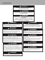
Safety Warnings
DANGER
WARNING
CAUTION
Hazards or unsafe practices which WILL result in
severe personal injury or death
Hazards or unsafe practices which COULD result in death or
severe personal injury
Hazards or unsafe practices which COULD result in minor
personal injury.
All safety messages will identify the hazard, tell you how
to reduce the chance of injury, and tell you what can happen if
the instructions are not followed.
WARNING
NEVER use this appliance as a space heater to heat or
warm the room. Doing so may result in carbon monoxide
poisoning and overheating of the drawer.
WARNING
To reduce the risk of re, electric shock, or injury to persons,
installation work and electrical wiring must be done by
quali ed people in accordance with all applicable codes
and standards, including re-rated conditions.
WARNING
To prevent possible damage to cabinets and cabinet nishes,
use only materials and nishes that will not discolor or
delaminate and will withstand temperatures up to 194°F
(90°C). Heat and moisture resistant adhesive must be used if
the product is to be installed in laminated cabinetry. Check
with your builder or cabinet supplier to make sure that the
materials meet these requirements.
CAUTION
This appliance is not to be used by persons (including
children) with reduced physical, sensory or mental
capabilities, or lack of experience and knowledge, unless
they have been given supervision or instruction concerning
the use of the appliance by a person responsible for their
safety. Children should be supervised to ensure that they do
not play with the appliance.
WARNING
DO NOT use the handle or oven door to lift the oven.
Remove door before installation to ensure that it is not used
to lift the unit. See installation section for door removal.
WARNING
The use of cabinets for storage above the oven may result
in potential re or burn hazard.
WARNING
Frame grounded by a 4-conductor cable assembly. See
installation section.
DO NOT USE AN EXTENSION CORD WITH THIS APPLIANCE.
SUCH USE MAY RESULT IN FIRE, ELECTRICAL SHOCK OR
OTHER PERSONAL INJURY
The oven is heavy—use extreme care when handling.
CAUTION
WARNING
ELECTRICAL GROUNDING INSTRUCTIONS
This oven must be electrically grounded in accordance
with local codes or, in the absence of local codes, with the
National Electrical Code, ANSI/NFPA-70 – latest edition.
WARNING
The misuse of the oven door(s) (e.g. stepping, sitting, or
leaning on them) can result in hazards or injuries and
damage to the product.

4
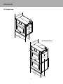
Dimensions
30” Single Oven
30” Double Oven
24” (61 cm)
29-3/8”
(74.6 cm)
29-3/4”
(75.6 cm)
24” (61 cm)
29-3/4”
(75.6 cm)
51-3/8”
(130.5 cm)

5
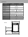
Speci cations
Side View
Description MVSOE630 MVDOE630
Overall width 29-3/4” (75.6 cm)
Overall height 29-3/8” (74.6 cm) 51-3/8” (130.5 cm)
Overall depth
To front of door glass
To front of handle
24” (61.0 cm)
26-7/16” (67.2 cm)
Cutout width
Standard Install
Flush mount
28-1/2” (72.4 cm)
30” (76.2 cm)
Cutout height
Standard Install
Flush Mount
28-1/4” (71.8 cm)
29-1/2” (74.9 cm)
50-5/8” (128.5 cm)
51-1/2” (130.8 cm)
Cutout depth
Standard Install / Flush Mount 24” (61.0 cm)
Electrical requirement 4-wire ground, 240 VAC, 30 amp electrical connection for single ovens/
50 amp for double ovens. Unit is equipped with No. 10 ground wire in
conduit. Should be fused separately.
Max Amp Usage 240 VAC - 24.0 amps
208 VAC - 20.8 amps
240 VAC - 40.0 amps
208 VAC - 34.7 amps
Interior width 25” (63.5 cm)
Interior height 16” (40.6 cm)
Interior depth 18-1/2” (50.0 cm)
Oven volume (AHAM Standard) 3.8 cu. ft.
Oven volume (total oven cavity) 4.3 cu. ft
24” (61.0 cm)
20-1/2”
(52.1 cm)
44-7/16”
(112.9 cm)
22-11/16”
(57.6 cm)

6
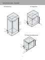
Cutout Dimensions - Standard
30” Single Oven30” Double Oven
30” Single Oven Undercounter
28-1/2”
(72.4 cm)
24”
(61.0 cm)
28-1/4”
(71.8 cm)
5” min.
(12.7 cm)
Junction box
location
4-3/4”
(12.1 cm) min.
to floor
30”
(72.4 cm)
28-1/4”
(
71.8 cm)
24”
(61.0 cm)
28-1/2”
(72.4 cm)
50-5/8”
(128.5 cm)
Flush mount
51-1/2”
(130.8 cm)
15-1/4”
(38.7 cm) min.
to floor
4”
(10.2 cm)
5” min.
(12.7 cm)
Junction box
location
4-3/4”
(12.1 cm)
(Floor to bottom
of cutout)
5” min.
(12.7 cm)
Junction box
location
4”
(10.2 cm)
24”
(61.0 cm)
4”
(10.2 cm)

7
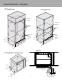
Cutout Dimensions - Integrated
30” Single Oven
30” Double Oven
30” Single Oven Undercounter
Finished
Surfaces
3/4” (1.9 cm)
Vertical
Blocking
on both
sides
24”
(61.0 cm)
30”
(76.2 cm)
51-1/2”
(130.8 cm)
5” min.
(12.7 cm)
Junction
box
location
4”
(10.2 cm)
15-1/4” min.
(38.7 cm) to the floor
3/4” (1.9 cm)
Horizontal
Blocking
across top
Finished
Surfaces
3/4”
(1.9 cm)
Vertical
Blocking
on both
sides
29-1/2”
(74.9 cm)
24”
(61.0 cm)
30”
(76.2 cm)
5” min.
(12.7 cm)
Junction
box
location
4”
(10.2 cm)
4-3/4” min.
(12.1 cm)
to the floor
3/4” (1.9 cm)
Horizontal
Blocking
across top
30”
(76.2 cm)
29-1/2”
(74.9 cm)
24”
(61.0 cm)
5” min.
(12.7 cm)
Junction box
location
4-3/4”
(12.1 cm)
(Floor to bottom
of cutout)
4”
(10.2 cm)
Top View
24” (61.0 cm)
24-7/8” (63.2 cm)
3” (7.6 cm)
3/4”
(1.9 cm)
7/8”
(2.2 cm)
Cabinet Door
Cabinet Door
3/4” (1.9 cm) gap between
top and side blocks on
both sides

8
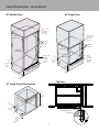
Cutout Dimensions - Flush Mount
30” Single Oven
30” Double Oven
30” Single Oven Undercounter
Finished
Surfaces
3/4” (1.9 cm)
Vertical
Blocking
on both
sides
24”
(61.0 cm)
30”
(76.2 cm)
51-1/2”
(130.8 cm)
5” min.
(12.7 cm)
Junction
box
location
4”
(10.2 cm)
15-1/4” min.
(38.7 cm) to the floor
3/4” (1.9 cm)
Horizontal
Blocking
across top
Finished
Surfaces
3/4”
(1.9 cm)
Vertical
Blocking
on both
sides
29-1/2”
(74.9 cm)
24”
(61.0 cm)
30”
(76.2 cm)
5” min.
(12.7 cm)
Junction
box
location
4”
(10.2 cm)
4-3/4” min.
(12.1 cm)
to the floor
3/4” (1.9 cm)
Horizontal
Blocking
across top
30”
(76.2 cm)
29-1/2”
(74.9 cm)
24”
(61.0 cm)
5” min.
(12.7 cm)
Junction box
location
4-3/4”
(12.1 cm)
(Floor to bottom
of cutout)
4”
(10.2 cm)
Top View
24” (61,0 cm)
24-7/8” (63,2 cm)
Porte de placard Porte de placard
3” (7,6 cm)
3/4”
(1,9 cm)
1-3/4”
(4,4 cm)
3/4” (1.9 cm) gap between
top and side blocks on
both sides

9
Electrical Requirements
• Oven requires a separate, grounded 4-wire, 240V (AC), 30 amp (single ovens) and 50 amp (double ovens) service with its own
circuit breaker.
• Wire sizes and connections must conform with the rating of the appliance and to the requirements of the National Electrical
Code, ANSI/NFPA-70 – latest edition, or Canadian Electrical Code, CSA C22.1-1982 and C22.2 No. 01982 – latest edition, and all
local codes and ordinances.
• Oven must be connected to the proper electrical voltage and frequency as speci ed on the model/serial rating plate (located
inside the vent ont the right sode of the oven).
• Oven must be connected to grounded metal permanent wiring system. Check with a quali ed electrician to make sure the oven
is properly grounded.
• Do not ground to a gas pipe.
• Do not use an extension cord with this appliance, because this may result in electrical shock or other personal injury.
• This unit is equipped with a No. 10 ground wire in the conduit.
• The electrical conduit must be kept to the top left for a ush installation. Never cut the conduit.
• Connect the exible armored cable directly to 4-wire, 240V household service. If codes permit and separate grounding wiring is
used, we recommend that a quali ed electrician determine the grounding path and that the wire gauge is in accordance with
local codes.
• Junction boxes installed on rear wall directly behind oven must be recessed.
• A UL-Listed conduit connector must be provided at the junction box.
• Do not install a fuse in the neutral or grounding circuit. We recommend a time-delayed fuse or circuit breaker. Connect directly to
the fused disconnect (or circuit breaker box) through exible armored, or non-metallic sheathed, copper cable (with grounding
wire).
Recommendations for Moving
•Only proper equipment should be used to move products.
• ALWAYS take steps to protect ooring at the installation
location when moving products.
General Information
WARNING
DO NOT use the handle or oven door to lift the oven.
Remove door before installation to ensure that it is not used
to lift the unit. See installation section for door removal. DO
NOT lift or carry the door by the handle
The oven is heavy—use extreme care when handling.
CAUTION
WARNING
FIRE OR ELECTRICAL SHOCK HAZARD
DO NOT use an extension cord with this
appliance. Such use may result in re, electrical
shock or other personal injury.
•Keep appliance area clear and free from combustible materials, gasoline and other ammable vapors.
•Disconnect the electrical supply prior to servicing or cleaning.
• When removing the appliance for cleaning or service, disconnect AC power supply and carefully remove the appliance by pulling
forward.
•Electrical requirements are listed in the product speci cations under the electrical requirements section.
Recommendations for Unpacking
•Products are shipped on pallets with foam footings and corrugated inner-packing and exterior hoods.
•Products are anchored to the pallet using metal straps that are screwed to the bottom of the product and the pallet.
•DO NOT remove protective packaging until you are ready to perform the installation.
•To remove the packaging, rst remove the staples located at the bottom perimeter of the corrugated cover.
•Remove the corrugated cover by lifting it o the product and remove the inner-packing.
•Detach the product from the metal anchor strip by removing the attachment screw.
•DO NOT remove the protective wrapping from the product control panel until the product is installed.
•All openings in the wall behind the appliance or in the oor under the appliance should be sealed.

10
Site Preparation
Note: It is recommended that a thorough site inspection be conducted PRIOR to unpacking and moving this appliance.
• Con rm available access to adequate power—see electrical requirements.
° Single oven units require a 30 amp circuit
° Double oven units require a 50 amp circuit
• Note: A minimum of 2” spacing above and below the oven to any other adjacent items is required for ventilation purposes. DO
NOT install single or double wall ovens side by side or stacked.
•It is recommended that 3/4” or thicker material be utilized to create a support platform for this appliance.
• BE SURE that support for this appliance is perpendicular to the front facing of the wall or cabinet before you perform the
installation.
•Use of a hydraulic lift is recommended for the installation of double oven units. Be careful not to bend lower trim/vent.
•All openings in the wall behind the appliance or in the oor under the appliance should be sealed.
•Keep appliance area clear and free from combustible materials, gasoline and other ammable vapors.
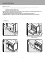
1
1
2
2
Remove wooden brace on front of pallet.
Open door completely. Rotate door hinge clip as
shown in illustration.
Installation
General Information
3 4
Close the door until it stops. Push in/lift door up/and then out. Repeat for all
doors.

11
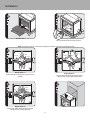
5
6
Remove racks.
Unscrew pallet screws from side of oven.
8
Neutral
Green
White
Black
Red
7a
Neutral
Green
White
Black
Red
7b
Neutral
Green
White
Black
Red
7c
Wiring option 1*
(connect the white and green to the incoming
neutral)
Wiring option 2*
(connect the white to the incoming neutral,
attach green to grounded junction box)
Wiring option 3*
(connect the white to the incoming neutral,
attach green to suitable ground)
Lift oven into position.
*Note: Check local code to see which wiring option should be used when grounding the unit.
Installation

12
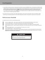
Installation
9
10
Push oven straight in.
Attach screws to the side of the framing.
Note: Two screws for single ovens, four screws
for double ovens (screws not included).
11 12
1
13
2
14
Replace racks
Replace door
Open door completely. Rotate door
hinge clip as shown in illustration.
Close door

13
1. Some stainless steel parts may have a protective wrap, which must be peeled o . All stainless steel body parts should be wiped
regularly with hot, soapy water at the end of each cooling period and with liquid cleaner designed for this material when soapy
water will not do the job. If build-up occurs, DO NOT use steel wool, or abrasive cloths, cleaners, or powders. If it is necessary
to scrape stainless steel surface to remove encrusted material, soak area with hot, wet towels to loosen the material, then
use a wooden or nylon spatula or scraper. DO NOT use a metal knife, spatula, or any other metal tool to scrape stainless steel
surfaces. Scratches are almost impossible to remove.
2. The interior of the oven should be washed thoroughly with hot, soapy water to remove lm residues and installation debris
before being used for food preparation, then rinsed and wiped dry. Solutions stronger than soapy water are rarely needed.
Final Preparation
Performance Checklist
A quali ed installer should carry out the following checks:
Check oven Bake Function—bake element on full power, center and outside broil elements at partial power.
Convection Bake function—bake and broil elements the same with the convection fan “ON”.
Check TruConvec™ function—TruConvec element (behind convection fan cover) “ON” and convection fan “ON”.
Check High Broil function—both broil elements at full power. Convection broil function is the same with convection fan
“ON”.
Check Medium Broil function—inner and outer broil elements pulse on and o .
Check Low Broil function—inner broil element only.
Check Self-Clean function—Door will lock in approximately 30 seconds, the center and outside broil elements will turn
“ON” and the bake element will turn “ON” at partial power. Check broil elements through window to make sure they are
“ON”, then abort self-clean cycle to unlock door.
Do not run self-clean cycle check for more than 10 minutes
with the oven racks and rack supports inside oven to avoid
discoloration due to the high temperature.
CAUTION

14
If service is required, call your authorized service agency.
Have the following information readily available.
• Model number
• Serial number
• Software Version
• Date purchased
• Name of dealer from whom purchased
Clearly describe the problem that you are having. If you are unable to obtain the name of an authorized service agency,
or if you continue to have service problems, contact Viking Range, LLC at 1-888-(845-4641), or write to:
VIKING RANGE, LLC
PREFERRED SERVICE
111 Front Street
Greenwood, Mississippi 38930 USA
Record the following information indicated below. You will need it if service is ever required.
The model and serial number for your oven can be found by opening the door and looking underneath the
control panel on the left hand side.
To access the software version, click the three dots above the time. Select Utility, select update.
Service Information

15
Record the information indicated below. You will need it if service is ever required.
Model number ________________________________________________________________________
Serial number _________________________________________________________________________
Software Version ______________________________________________________________________
Date of purchase ______________________________________________________________________
Date installed _________________________________________________________________________
Dealer’s name ________________________________________________________________________
Dealer's Address ______________________________________________________________________
If service requires installation of parts, use only authorized parts to ensure protection under the warranty.
KEEP THIS MANUAL FOR FUTURE REFERENCE.

060119-000C EN
Viking Range, LLC
111 Front Street
Greenwood, Mississippi 38930 USA
(662) 455-1200
For product information,
call 1-888-(845-4641)
or visit our web site at vikingrange.com
(013018)
-
 1
1
-
 2
2
-
 3
3
-
 4
4
-
 5
5
-
 6
6
-
 7
7
-
 8
8
-
 9
9
-
 10
10
-
 11
11
-
 12
12
-
 13
13
-
 14
14
-
 15
15
-
 16
16


Viking MVDOE630BG Operating instructions
- Category
- Ovens
- Type
- Operating instructions
- This manual is also suitable for
Ask a question and I''ll find the answer in the document
Finding information in a document is now easier with AI
Related papers
-
Viking CMVSOE630 Installation guide
-
Viking RVSOE330SS Installation guide
-
Viking DDOE305T User manual
-
-
Viking MVWD630SBG Installation guide
-
-
-
Viking DEDO530 Installation guide
-
-
Viking VSOE527SS Installation guide
Other documents
-
Viking Range RVSOE Installation guide
-
Coyote CDPC31 Installation guide
-
Smeg SF112U Instructions Manual
-
KitchenAid W10045010 User manual
-
KitchenAid KODE900HBS Installation guide
-
Ancona AN-2303 User manual
-
-
Electrolux E30EW75DSS1 Installation guide
-
Hillsdale Furniture 6124GTB Operating instructions
-
Coyote CCD-WD Installation guide