Firepower Plasma Cutting Power Supply User manual
- Category
- Welding System
- Type
- User manual

Plasma Cutting
Power Supply
Firepower
TM
FP-38 Power Supply
Operating Manual
May 5, 2003 Manual No. 0-2967
A-03286


WARNINGS
Read and understand this entire Manual and your employer’s safety practices before installing, oper-
ating, or servicing the equipment.
While the information contained in this Manual represents the Manufacturer's best judgement, the
Manufacturer assumes no liability for its use.
Plasma Cutting Power Supply
Firepower
TM
FP-38 Power Supply
Operating Manual Number 0-2967
Published by:
Thermal Dynamics Corporation
82 Benning Street
West Lebanon, New Hampshire, USA 03784
(603) 298-5711
www.firepoweronline.com
Copyright 2002 by
Thermal Dynamics Corporation
All rights reserved.
Reproduction of this work, in whole or in part, without written permission of the
publisher is prohibited.
The publisher does not assume and hereby disclaims any liability to any party for
any loss or damage caused by any error or omission in this Manual, whether such
error results from negligence, accident, or any other cause.
Printed in the United States of America
Publication Date: May 5, 2003
Record the following information for Warranty purposes:
Where Purchased:____________________________________
Purchase Date:_______________________________________
Power Supply Serial #:________________________________
Torch Serial #:________________________________________

TABLE OF CONTENTS
SECTION 1:
GENERAL INFORMATION ............................................................................................... 1-1
1.01 Notes, Cautions and Warnings ..................................................................... 1-1
1.02 Important Safety Precautions ....................................................................... 1-1
1.03 Publications.................................................................................................. 1-2
1.07 Declaration of Conformity............................................................................. 1-4
1.08 Statement of Warranty.................................................................................. 1-5
SECTION 2: SPECIFICATIONS............................................................................................... 2-1
Options and Accessories ..................................................................................... 2-2
Torch Specifications ............................................................................................. 2-2
SECTION 3: INSTALLATION .................................................................................................... 3-1
3.1 Unpacking .................................................................................................... 3-1
3.2 Lifting Options .............................................................................................. 3-1
3.3 Primary Input Power Connections ................................................................ 3-2
3.4 Gas Connections ......................................................................................... 3-3
3.5 Torch Connections ....................................................................................... 3-6
SECTION 4:
OPERATION ..................................................................................................................... 4-1
4.01 Product Features.......................................................................................... 4-1
4.02 Preparations For Operating .......................................................................... 4-3
4.03 Sequence of Operation ................................................................................ 4-7
SECTION 5:
SERVICE .......................................................................................................................... 5-1
5.01 General Maintenance ................................................................................... 5-1
5.02 Common Faults............................................................................................ 5-4
5.03 Basic Troubleshooting Guide ........................................................................ 5-5
SECTION 6:
PARTS LISTS.................................................................................................................... 6-1
6.01 Introduction .................................................................................................. 6-1
6.02 Ordering Information .................................................................................... 6-1
6.03 Replacement Assemblies............................................................................ 6-1
6.04 Power Supply Replacement Parts ................................................................ 6-1
6.05 Options and Accessories ............................................................................. 6-2
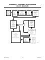
APPENDIX 1: SEQUENCE OF OPERATION (BLOCK DIAGRAM) .........................................A-1
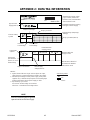
APPENDIX 2: DATA TAG INFORMATION .................................................................................A-2
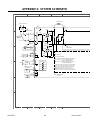
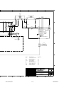
APPENDIX 3: SYSTEM SCHEMATIC.......................................................................................A-4

May 14, 2002 1-1 GENERAL INFORMATION
SECTION 1:
GENERAL INFORMATION
1.01 Notes, Cautions and Warnings
Throughout this manual, notes, cautions, and warnings
are used to highlight important information. These high-
lights are categorized as follows:
NOTE
An operation, procedure, or background informa-
tion which requires additional emphasis or is help-
ful in efficient operation of the system.
CAUTION
A procedure which, if not properly followed, may
cause damage to the equipment.
WARNING
A procedure which, if not properly followed, may
cause injury to the operator or others in the oper-
ating area.
1.02 Important Safety Precautions
WARNINGS
OPERATION AND MAINTENANCE OF
PLASMA ARC EQUIPMENT CAN BE DAN-
GEROUS AND HAZARDOUS TO YOUR
HEALTH.
Plasma arc cutting produces intense electric and
magnetic emissions that may interfere with the
proper function of cardiac pacemakers, hearing aids,
or other electronic health equipment. Persons who
work near plasma arc cutting applications should
consult their medical health professional and the
manufacturer of the health equipment to determine
whether a hazard exists.
To prevent possible injury, read, understand and
follow all warnings, safety precautions and instruc-
tions before using the equipment. Call 1-603-298-
5711 or your local distributor if you have any ques-
tions.
GASES AND FUMES
Gases and fumes produced during the plasma cutting
process can be dangerous and hazardous to your health.
• Keep all fumes and gases from the breathing area.
Keep your head out of the welding fume plume.
• Use an air-supplied respirator if ventilation is not
adequate to remove all fumes and gases.
• The kinds of fumes and gases from the plasma arc
depend on the kind of metal being used, coatings
on the metal, and the different processes. You must
be very careful when cutting or welding any met-
als which may contain one or more of the follow-
ing:
Antimony Chromium Mercury
Arsenic Cobalt Nickel
Barium Copper Selenium
Beryllium Lead Silver
Cadmium Manganese Vanadium
• Always read the Material Safety Data Sheets
(MSDS) that should be supplied with the material
you are using. These MSDSs will give you the in-
formation regarding the kind and amount of fumes
and gases that may be dangerous to your health.
• For information on how to test for fumes and gases
in your workplace, refer to item 1 in Subsection 1.03,
Publications in this manual.
• Use special equipment, such as water or down draft
cutting tables, to capture fumes and gases.
• Do not use the plasma torch in an area where com-
bustible or explosive gases or materials are located.
• Phosgene, a toxic gas, is generated from the vapors
of chlorinated solvents and cleansers. Remove all
sources of these vapors.
• This product, when used for welding or cutting, pro-
duces fumes or gases which contain chemicals
known to the State of California to cause birth de-
fects and, in some cases, cancer. (California Health
& Safety Code Sec. 25249.5 et seq.)
ELECTRIC SHOCK
Electric Shock can injure or kill. The plasma arc process
uses and produces high voltage electrical energy. This
electric energy can cause severe or fatal shock to the op-
erator or others in the workplace.
• Never touch any parts that are electrically “live” or
“hot.”

GENERAL INFORMATION 1-2 May 14, 2002
• Wear dry gloves and clothing. Insulate yourself
from the work piece or other parts of the welding
circuit.
• Repair or replace all worn or damaged parts.
• Extra care must be taken when the workplace is
moist or damp.
• Install and maintain equipment according to NEC
code, refer to item 9 in Subsection 1.03, Publications.
• Disconnect power source before performing any ser-
vice or repairs.
• Read and follow all the instructions in the Operat-
ing Manual.
FIRE AND EXPLOSION
Fire and explosion can be caused by hot slag, sparks, or
the plasma arc.
• Be sure there is no combustible or flammable mate-
rial in the workplace. Any material that cannot be
removed must be protected.
• Ventilate all flammable or explosive vapors from
the workplace.
• Do not cut or weld on containers that may have held
combustibles.
• Provide a fire watch when working in an area where
fire hazards may exist.
• Hydrogen gas may be formed and trapped under
aluminum workpieces when they are cut underwa-
ter or while using a water table. DO NOT cut alu-
minum alloys underwater or on a water table un-
less the hydrogen gas can be eliminated or
dissipated. Trapped hydrogen gas that is ignited
will cause an explosion.
NOISE
Noise can cause permanent hearing loss. Plasma arc pro-
cesses can cause noise levels to exceed safe limits. You
must protect your ears from loud noise to prevent per-
manent loss of hearing.
• To protect your hearing from loud noise, wear pro-
tective ear plugs and/or ear muffs. Protect others
in the workplace.
• Noise levels should be measured to be sure the deci-
bels (sound) do not exceed safe levels.
• For information on how to test for noise, see item 1
in Subsection 1.03, Publications, in this manual.
PLASMA ARC RAYS
Plasma Arc Rays can injure your eyes and burn your skin.
The plasma arc process produces very bright ultra violet
and infra red light. These arc rays will damage your eyes
and burn your skin if you are not properly protected.
• To protect your eyes, always wear a welding hel-
met or shield. Also always wear safety glasses with
side shields, goggles or other protective eye wear.
• Wear welding gloves and suitable clothing to pro-
tect your skin from the arc rays and sparks.
• Keep helmet and safety glasses in good condition.
Replace lenses when cracked, chipped or dirty.
• Protect others in the work area from the arc rays.
Use protective booths, screens or shields.
• Use the shade of lens as suggested in the following
per ANSI/ASC Z49.1:
Minimum Protective Suggested
Arc Current Shade No. Shade No.
Less Than 300* 8 9
300 - 400* 9 12
400 - 800* 10 14
* These values apply where the actual arc is clearly
seen. Experience has shown that lighter filters may
be used when the arc is hidden by the workpiece.
1.03 Publications
Refer to the following standards or their latest revisions
for more information:
1. OSHA, SAFETY AND HEALTH STANDARDS, 29CFR
1910, obtainable from the Superintendent of Documents,
U.S. Government Printing Office, Washington, D.C.
20402
2. ANSI Standard Z49.1, SAFETY IN WELDING AND
CUTTING, obtainable from the American Welding So-
ciety, 550 N.W. LeJeune Rd, Miami, FL 33126
3. NIOSH, SAFETY AND HEALTH IN ARC WELDING
AND GAS WELDING AND CUTTING, obtainable from
the Superintendent of Documents, U.S. Government
Printing Office, Washington, D.C. 20402
4. ANSI Standard Z87.1, SAFE PRACTICES FOR OCCU-
PATION AND EDUCATIONAL EYE AND FACE PRO-
TECTION, obtainable from American National Stan-
dards Institute, 1430 Broadway, New York, NY 10018
5. ANSI Standard Z41.1, STANDARD FOR MEN’S
SAFETY-TOE FOOTWEAR, obtainable from the Ameri-
can National Standards Institute, 1430 Broadway, New
York, NY 10018

May 14, 2002 1-3 GENERAL INFORMATION
6. ANSI Standard Z49.2, FIRE PREVENTION IN THE USE
OF CUTTING AND WELDING PROCESSES, obtain-
able from American National Standards Institute, 1430
Broadway, New York, NY 10018
7. AWS Standard A6.0, WELDING AND CUTTING CON-
TAINERS WHICH HAVE HELD COMBUSTIBLES, ob-
tainable from American Welding Society, 550 N.W.
LeJeune Rd, Miami, FL 33126
8. NFPA Standard 51, OXYGEN-FUEL GAS SYSTEMS
FOR WELDING, CUTTING AND ALLIED PRO-
CESSES, obtainable from the National Fire Protection
Association, Batterymarch Park, Quincy, MA 02269
9. NFPA Standard 70, NATIONAL ELECTRICAL CODE,
obtainable from the National Fire Protection Associa-
tion, Batterymarch Park, Quincy, MA 02269
10. NFPA Standard 51B, CUTTING AND WELDING PRO-
CESSES, obtainable from the National Fire Protection
Association, Batterymarch Park, Quincy, MA 02269
11. CGA Pamphlet P-1, SAFE HANDLING OF COM-
PRESSED GASES IN CYLINDERS, obtainable from the
Compressed Gas Association, 1235 Jefferson Davis
Highway, Suite 501, Arlington, VA 22202
12. CSA Standard W117.2, CODE FOR SAFETY IN WELD-
ING AND CUTTING, obtainable from the Canadian
Standards Association, Standards Sales, 178 Rexdale
Boulevard, Rexdale, Ontario, Canada M9W 1R3
13. NWSA booklet, WELDING SAFETY BIBLIOGRAPHY
obtainable from the National Welding Supply Associa-
tion, 1900 Arch Street, Philadelphia, PA 19103
14. American Welding Society Standard AWSF4.1, RECOM-
MENDED SAFE PRACTICES FOR THE PREPARA-
TION FOR WELDING AND CUTTING OF CONTAIN-
ERS AND PIPING THAT HAVE HELD HAZARDOUS
SUBSTANCES, obtainable from the American Welding
Society, 550 N.W. LeJeune Rd, Miami, FL 33126
15. ANSI Standard Z88.2, PRACTICE FOR RESPIRATORY
PROTECTION, obtainable from American National
Standards Institute, 1430 Broadway, New York, NY
10018

GENERAL INFORMATION 1-4 May 14, 2002
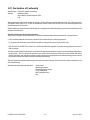
1.07 Declaration of Conformity
Manufacturer: Thermal Dynamics Corporation
Address: 82 Benning Street
West Lebanon, New Hampshire 03784
USA
The equipment described in this manual conforms to all applicable aspects and regulations of the ‘Low Voltage Directive’
(European Council Directive 73/23/EEC as amended by Council Directive 93/68/EEC) and to the National legislation for
the enforcement of this Directive.
Serial numbers are unique with each individual piece of equipment and details description, parts used to manufacture a unit
and date of manufacture.
National Standard and Technical Specifications
The product is designed and manufactured to a number of standards and technical requirements. Among them are:
* CSA (Canadian Standards Association) standard C22.2 number 60 for Arc welding equipment.
* UL (Underwriters Laboratory) rating 94VO flammability testing for all printed-circuit boards used.
* ISO/IEC 60974-1 (BS 638-PT10) (EN 60 974-1) (EN50192) (EN50078) applicable to plasma cutting equipment and associ-
ated accessories.
* Extensive product design verification is conducted at the manufacturing facility as part of the routine design and manufac-
turing process. This is to ensure the product is safe, when used according to instructions in this manual and related
industry standards, and performs as specified. Rigorous testing is incorporated into the manufacturing process to ensure
the manufactured product meets or exceeds all design specifications.
Thermal Dynamics has been manufacturing products for more than 30 years, and will continue to achieve excellence in our
area of manufacture.
Manufacturers responsible representative: Giorgio Bassi
Managing Director
Thermal Dynamics Europe
Via rio Fabbiani 8A
40067 Rastignano (BO)
Italy

May 14, 2002 1-5 GENERAL INFORMATION
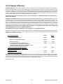
1.08 Statement of Warranty
LIMITED WARRANTY: Firepower® (hereinafter “Firepower”) warrants that its products will be free of defects in workmanship or
material. Should any failure to conform to this warranty appear within the time period applicable to the Firepower products as stated
below, Firepower shall, upon notification thereof and substantiation that the product has been stored, installed, operated, and maintained
in accordance with Firepower’s specifications, instructions, recommendations and recognized standard industry practice, and not subject
to misuse, repair, neglect, alteration, or accident, correct such defects by suitable repair or replacement, at Firepower’s sole option, of
any components or parts of the product determined by Firepower to be defective.
THIS WARRANTY IS EXCLUSIVE AND IS IN LIEU OF ANY WARRANTY OF MERCHANTABILITY OR FITNESS FOR A
PARTICULAR PURPOSE.
LIMITATION OF LIABILITY: Firepower shall not under any circumstances be liable for special or consequential damages, such as, but
not limited to, damage or loss of purchased or replacement goods, or claims of customers of distributor (hereinafter “Purchaser”) for
service interruption. The remedies of the Purchaser set forth herein are exclusive and the liability of Firepower with respect to any
contract, or anything done in connection therewith such as the performance or breach thereof, or from the manufacture, sale, delivery,
resale, or use of any goods covered by or furnished by Firepower whether arising out of contract, negligence, strict tort, or under any
warranty, or otherwise, shall not, except as expressly provided herein, exceed the price of the goods upon which such liability is based.
THIS WARRANTY BECOMES INVALID IF REPLACEMENT PARTS OR ACCESSORIES ARE USED WHICH MAY IMPAIR THE
SAFETY OR PERFORMANCE OF ANY FIREPOWER PRODUCT.
THIS WARRANTY IS INVALID IF THE PRODUCT IS SOLD BY NON-AUTHORIZED PERSONS.
The limited warranty periods for Firepower products shall be as follows: A maximum of four (4) years from date of sale to an authorized
distributor and a maximum of three (3) years from date of sale by such distributor to the Purchaser, and with the following further
limitations on such three (3) year period.
FP-38 POWER SUPPLIES PARTS LABOR
MAIN POWER MAGNETICS ...................................................................................................... 3 YEARS ...................1 YEAR
ORIGINAL MAIN POWER RECTIFIER ..................................................................................... 3 YEARS ...................1 YEAR
CONTROL PC BOARD .................................................................................................................. 3 YEARS ...................1 YEAR
ALL OTHER CIRCUITS AND COMPONENTS ......................................................................... 1 YEAR ....................1 YEAR
INCLUDING, BUT NOT LIMITED TO, STARTING
CIRCUIT, CONTACTORS, RELAYS, SOLENOIDS, PUMPS,
POWER SWITCHING SEMI-CONDUCTORS
CONSOLES, CONTROL EQUIPMENT, HEAT ............................................................................. 1 YEAR .................. 1 YEAR
EXCHANGES, AND ACCESSORY EQUIPMENT
TORCH AND LEADS ......................................................................................................................... 1 YEAR .................. 1 YEAR
REPAIR/REPLACEMENT PARTS .................................................................................................... 90 DAYS .................. NONE
Warranty repairs or replacement claims under this limited warranty must be submitted by an authorized Firepower repair facility
within thirty (30) days of the repair. No transportation costs of any kind will be paid under this warranty. Transportation charges to
send products to an authorized warranty repair facility shall be the responsibility of the customer. All returned goods shall be at the
customer’s risk and expense. This warranty supersedes all previous Firepower warranties.
Effective May 5, 2000

GENERAL INFORMATION 1-6 May 14, 2002

Manual 0-2967 2-1 SPECIFICATIONS
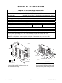
SECTION 2: SPECIFICATIONS
15.75"
400 mm
10"
254 mm
21"
0.53 m
43 lb / 19.5 kg
A-03378
6"
150 mm
A-03379
6"
150 mm
6"
150 mm
6"
150 mm
Weight includes torch & leads, input power cord,
and work cable with clamp.
CAUTION
Provide clearance for proper air flow through
the power supply. Operation without proper
air flow will inhibit proper cooling and reduce
duty cycle.
Input Power (See Note 1)
Power Sensing
Input Power Cable
Output Current
Power Supply Gas Filtering Ability
Ambient Temperature
Duty Cycle 35% 60%
DC Voltage 78 vdc 89 vdc
Current 30 Amps 22 Amps
Fire
p
ower FP-38 Power Su
pp
l
y
S
p
ecifications
120 VAC (± 10%), Single-Phase, 50/60 Hz
208 - 230 VAC (± 10%), Single-Phase, 50/60 Hz
Automatic Voltage Selection. See Note 1.
Cable with plug, for 120VAC, 20-Amp Single-Phase input power. (Note 2)
20-30 Amps, continuously variable
Particulates to 20 Microns (Note 4)
Fire
p
ower FP-38 Power Su
pp
l
y
Dut
y
C
y
cle
(
Note 3
)
104° F (40° C)
n/a %
n/a vdc
n/a Amps
3
. Duty Cycle is the percentage of time the system can be operated without overheating. Duty cycle is
reduced if primary input voltage (AC) is low or the DC voltage is higher than shown in this chart.
4
. Air supply must be free of oil, moisture, and other contaminants. Excessive oil and moisture may cause
double-arcing, rapid tip wear, or even complete torch failure. Contaminants may cause poor cutting
performance and rapid electrode wear. Optional filters provide increased filtering capabilities.
Notes
1
. Power supply accepts 120-230 VAC input power. No manual switching is required.
2.
Plug must be replaced for 208/230V input power.

SPECIFICATIONS 2-2 Manual 0-2967
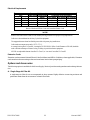
Electrical Requirements
Input
Power Input Current Input
Voltage Freq. (kVA)
(Amps) Fuse (Amps) Wire (AWG) Wire (Canada)
(Volts) (Hz) 1-Ph 1-Ph 1-Ph 1-Ph 1-Ph
120 50 / 60
3.629351212
208 50 / 60
3.516201212
230 50 / 60
3.414201212
Firepower FP-38 Input Power Requirements
Suggested Sizes (S ee Notes)
Line Voltages with Suggested Circuit Protection and Wire Sizes
Based on National Electric Code and Canadian Electric Code
NOTES
Refer to Local and National Codes or local authority having jurisdiction for proper wiring requirements.
Cable size is de-rated based on the Duty Cycle of the equipment.
The suggested sizes are based on flexible power cable with power plug installations.
Cable conductor temperature used is 167° F (75° C).
An energy limiting fuse UL Class RK-1 (examples: BUSS LPS/LPN-RK or Gould-Shawmut AZK-A6K) should be
used to minimize damage to Plasma Cutting, Welding or power distribution equipment.
NEVER use replaceable element fuses like UL Class H, or "one-time" fuses like UL Class K5.
Extension Cords
Extension cords must meet National Electric Code Guidelines (and OSHA Guidelines, where applicable). Extension
cords must have the same rating as the service and must have a three-pronged plug.
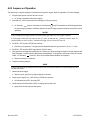
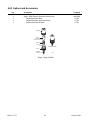
Options and Accessories
The following options is available for this Power Supply. Section 6 provides catalog numbers and ordering informa-
tion.
A. Single-Stage Air Filter Kit
A single-stage air filter for use on compressed air shop systems. Highly effective at removing moisture and
particulate matter from the air stream to at least 0.85 microns.

Manual 0-2967 3-1 INSTALLATION
SECTION 3: INSTALLATION
3.1 Unpacking
1. Use the packing lists to identify and account for each item.
2. Inspect each item for possible shipping damage. If damage is evident, contact your distributor and / or shipping
company before proceeding with the installation.
3. Record Power Supply and Torch model and serial numbers, purchase date and vendor name, in the information
block at the front of this manual.
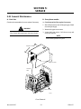
3.2 Lifting Options
The Power Supply includes a handle for hand lifting only. Be sure unit is lifted and transported safely and securely.
WARNINGS
Do not touch live electrical parts.
Disconnect input power cord before moving unit.
FALLING EQUIPMENT can cause serious personal injury and can damage equipment.
HANDLE is not for mechanical lifting.
• Only persons of adequate physical strength should lift the unit.
• Lift unit by the handles, using two hands. Do not use straps for lifting.
• Use optional cart or similar device of adequate capacity to move unit.
• Place unit on a proper skid and secure in place before transporting with a fork lift or other vehicle.

INSTALLATION 3-2 Manual 0-2967
3.3 Primary Input Power Connections
CAUTION
Check your power source for correct voltage before plugging in or connecting the unit. The primary power source,
fuse, and any extension cords used must conform to local electrical code and the recommended circuit protection and
wiring requirements as specified in Section 2.
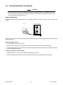
Power Cord and Plug
This power supply includes an input power cord and plug suitable for 120 VAC, 20 Amp, Single - Phase input
power.
A-03382
120 V, 20A, 1Ø
For 208 / 230 VAC input power, replace the supplied power plug. Use only an approved replacement input power
plug with ground.
Replace the plug as follows:
1. Cut the original cord close to the plug.
2. Strip back the outer cord cover as needed to connect the inner conductors to the replacement plug.
3. Connect conductors to the plug contacts according to the plug manufacturer's instructions. All three conductors
must be connected to the plug.
Connect the input power cord as follows:
1. Check the power source for correct voltage before plugging in the unit.
2. Connect the input power cable (or close the main disconnect switch) to supply power to the system.

Manual 0-2967 3-3 INSTALLATION
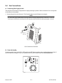
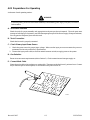
3.4 Gas Connections
A. Connecting Gas Supply to Unit
The connection is the same for compressed air or high pressure gas cylinders. Refer to subsection 3.4-C if an optional
air line filter is to be installed.
1. Connect the gas line to the inlet port. The illustration shows typical fittings as an example.
NOTE
For a secure seal, apply thread sealant to the fitting threads, according to manufacturer's instructions. Do Not use
Teflon tape as a thread sealer, as small particles of the tape may break off and block the small gas passages in the torch.
A-03272
Min. 1/4 inch
6.4 mm
Gas Connection to Inlet Port
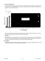
B. Check Air Quality
To test the quality of air, put the RUN / SET switch in the SET (down) position, place a welding filter lens in front of
the torch and turn on the gas. Any oil or moisture in the air will be visible on the lens. Do not start an arc!
A-03385
A
3020
26
28
24
22

INSTALLATION 3-4 Manual 0-2967
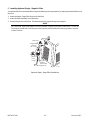
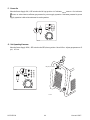
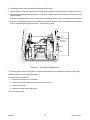
C. Installing Optional Single - Stage Air Filter
An optional filter kit is recommended for improved filtering with compressed air, to keep moisture and debris out of
the torch.
1. Attach the Single - Stage Filter Hose to the Inlet Port.
2. Attach the Filter Assembly to the filter hose.
3. Connect the gas line to the Filter. The illustration shows typical fittings as an example.
NOTE
For a secure seal, apply thread sealant to the fitting threads, according to the maker's instructions. Do Not use
Teflon tape as a thread sealer, as small particles of the tape may break off and block the small gas passages in the torch.
Connect as follows:
A-03281
1/4 NPT
Hose Fitting
Hose
Clamp
Gas Supply Hose
Filter Hose
Single-Stage
Filter Kit
No. 7-7507
Optional Single - Stage Filter Installation

Manual 0-2967 3-5 INSTALLATION
D. Using High Pressure Gas Cylinders
When using high pressure gas cylinders as the gas supply:
1. Refer to the manufacturer’s specifications for installation and maintenance procedures for high pressure gas
regulators.
2. Examine the cylinder valves to be sure they are clean and free of oil, grease or any foreign material. Briefly open
each cylinder valve to blow out any dust which may be present.
3. The cylinder must be equipped with an adjustable high - pressure regulator capable of outlet pressures up to 100
psi (6.9 bar) maximum and flows of at least 300 scfh (141.5 lpm).
4. Connect gas supply hose to the cylinder.
NOTE
Pressure should be set at 100 psi (6.9 bar) at the high pressure gas cylinder regulator.
Supply hose must be at least 1/4 inch (6 mm) I.D.
For a secure seal, apply thread sealant to the fitting threads, according to manufacturer's instructions. Do Not use
Teflon tape as a thread sealer, as small particles of the tape may break off and block the small gas passages in the torch.

INSTALLATION 3-6 Manual 0-2967
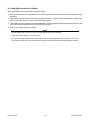
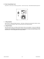
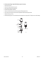
3.5 Torch Connections
If necessary, connect the torch to the Power Supply. Connect only the model SL60 Torch to this power supply.
WARNING
Disconnect primary power at the source before connecting the torch.
1. Align the male connector (on the torch lead) with the female receptacle on the power supply. Press the
connector into the receptacle fully.
2. Turn the locking ring on the male connector fully clockwise until it clicks.
A-03380
1
2
Connecting the Torch to the Power Supply
3. The system is ready for operation.

Manual 0-2967 4-1 OPERATION
SECTION 4:
OPERATION
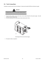
4.01 Product Features
A. General Features
A-03287
Handle and Leads WrapGas Pressure Knob
Torch Leads
Connector
Work Cable
and Clamp
Control Panel

OPERATION 4-2 Manual 0-2967
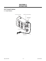
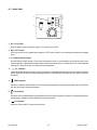
B. Control Panel
A-03283
3
1
4
5
6
2
A
3020
26
28
24
22
7
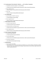
1. ON / OFF Switch
Controls input power to the power supply. Up is ON, down is OFF.
2. RUN / SET Switch
RUN (up) position is for general torch operation. SET (down) position is for setting gas pressure and purging
lines.
3. (A) Output Current Control
Sets the desired output current. If the overload protection (fuse or circuit breaker) on the input power circuit
opens frequently, either reduce cutting output, reduce the cutting time, or connect the unit to more adequate
input power. Refer to Section 2 for input power requirements.
4. AC Indicator
Steady light indicates power supply is ready for operation. Blinking light indicates unit is in protective interlock
mode. Shut unit off, shut off or disconnect input power, correct the fault, and restart the unit. Refer to Section 5
for details.
5. TEMP Indicator
Indicator is normally OFF. Indicator is ON when internal temperature exceeds normal limits. Shut unit OFF; let
the unit cool before continuing operation.
6. GAS Indicator
Indicator is ON when adequate input gas pressure for power supply operation is present. Minimum pressure for
power supply operation is below minimum for torch operation.
7. DC Indicator
Indicator is ON when DC output circuit is active.
Page is loading ...
Page is loading ...
Page is loading ...
Page is loading ...
Page is loading ...
Page is loading ...
Page is loading ...
Page is loading ...
Page is loading ...
Page is loading ...
Page is loading ...
Page is loading ...
Page is loading ...
Page is loading ...
Page is loading ...
Page is loading ...
Page is loading ...
Page is loading ...
Page is loading ...
Page is loading ...
Page is loading ...
Page is loading ...
Page is loading ...
Page is loading ...
-
 1
1
-
 2
2
-
 3
3
-
 4
4
-
 5
5
-
 6
6
-
 7
7
-
 8
8
-
 9
9
-
 10
10
-
 11
11
-
 12
12
-
 13
13
-
 14
14
-
 15
15
-
 16
16
-
 17
17
-
 18
18
-
 19
19
-
 20
20
-
 21
21
-
 22
22
-
 23
23
-
 24
24
-
 25
25
-
 26
26
-
 27
27
-
 28
28
-
 29
29
-
 30
30
-
 31
31
-
 32
32
-
 33
33
-
 34
34
-
 35
35
-
 36
36
-
 37
37
-
 38
38
-
 39
39
-
 40
40
-
 41
41
-
 42
42
-
 43
43
-
 44
44


Firepower Plasma Cutting Power Supply User manual
- Category
- Welding System
- Type
- User manual
Ask a question and I''ll find the answer in the document
Finding information in a document is now easier with AI
Related papers
-
ESAB Plasma Cutting Power Supply User manual
-
-
-
-
-
-
-
ESAB FP-160 User manual
-
-
Other documents
-
-
Matco Tools MA48 User manual
-
-
-
ITT Conoflow Thermostat Installation guide
-
-
-
-
-
ESAB Firepower MST 140i 3-IN-1 Multi Process Welding System User manual