Moxa Transio A52/A53 Series Quick setup guide
- Type
- Quick setup guide

P/N: 1802000520518
*1802000520518*
Transio A52/A53 Series
Quick Installation Guide
Version 8.1, January 2021
Technical Support Contact Information
www.moxa.com/support
2021 Moxa Inc. All rights reserved.

- 2 -
Overview
The Transio A52/A53 are smart RS-232 to RS-422/485 bi-directional
converters that allow one RS-232 port to be converted into an RS-422 or
RS-485 port. With the A52/A53 you can control up to 32 devices within
1.2 km in a multidrop environment.
To ease 2-wire RS-485 half-duplex control, Automatic Data Direction
Control (ADDC) intelligence, which does not requires a baudrate switch
setting, is designed into each A52/A53 to simplify your RS-485 software
programming. Your applications can easily manage data transmitting and
receiving via the half-duplex RS-485 port without using additional code.
Compared to other products that require using switches to set the clock
speed manually, the A52/A53 let you avoid many development and
maintenance hassles.
To meet the high reliability required by harsh industrial environments, all
RS-422/485 signals provide TVS protection. In addition, the A53 provides
2 KV of optical isolation protection for all signals at the RS-422/485 end.
Features and Specifications
• Serial interface: RS-232, RS-422/485
• Port types:
RS-232: RJ45;
RS-422/485: RJ45 or Terminal Block
• High speed, baudrate up to 921.6 Kbps; no switch setting needed
• Signals:
RS-232: TxD, RxD, RTS, CTS, DTR, DSR, DCD, GND;
RS-422: TxD+(B)/-(A), RxD+(B)/-(A), RTS+(B)/-(A), CTS+(B)/-(A),
GND;
RS-485-Data+(B)/-(A), GND
• Supports Automatic Data Direction Control (ADDC) with no baudrate
switch settings for RS-485
• RS-485 data control modes: auto (ADDC) or by RTS
• RS-422 supports CTS, RTS signals for hardware flow control
• LED indicators for power and 4 signal states (TxD, RxD, RTS, CTS)
• All RS-422/485 signals provide TVS protection.
• All RS-422/485 signals support up to 2 KV (DC) of optical isolation
protection (A53 only)
• Provides overloading protection when there are 2 signals shorted
together at the RS-422/485 end
• Built-in 120 ohm termination resistors for RS-422/RS-485 (selectable
by jumper in RS-485 mode)
• Supports up to 32 units connected in an RS-485 multidrop network
• CE/FCC approval
• 9 V 1.5 A UL 110/230 V power adaptor can support up to 4 converters

- 3 -
• An external power adaptor is required, with input voltage for the
converter ranging from DC +9V to +30V.
• Operating temperature: 0 to 55°C
• Dimensions: 90 x 60 x 21 mm
• Mounting Kit: Plastic Plates and screws for mounting the A52/A53 on
a wall or surface.
• Power consumption:
A52: 157 mA max. (+9V);
A53: 285 mA max. (+9V)
Applications
• Multipoint data acquisition
•
Factory automation
•
Remote serial device control
• Building security automation
•
Critical industrial control
Installation
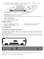
Switch and jumper settings
To change the operation mode, remove the two screws on the top of the
converter, open the cover, and then use the array of sliding switches to set
the desired mode.
DIP switches are used to select the operation mode (RS-422 or RS-485).
For RS-485 mode, the control mode (By RTS or ADDC) is also set by DIP
switch.
AUTO
485
RTS
422
JP
Internal view of A52/A53 (*default settings)
SW1
SW2
RS-422 mode
Off
By RTS
Off
RS-485 mode
On*
Auto Data Direction Control (ADDC)
On*
In RS-422 mode, RxD is automatically set with a 120 ohm terminating
resistor.
In RS-485 mode, the 120 ohm terminating resistor is set by one jumper.
When shorted, the resistor is enabled.

- 4 -
Basic Communication Wiring
Before placing a converter in an existing network, the converter should be
properly configured. The following diagrams show typical layouts for both
converters.
LED Indicators
LED indicators for TxD, RxD, RTS, CTS signals and PWR are located on the
top of the A52/A53. The indicator light is NOT lit when there is no signal,
or the power is off.
TxD:
Shows green when connected and transmitting data from RS-232
to RS
-422/485.
RxD:
Shows green when connected and receiving data from RS-232 to
RS
-422/485.
RTS:
S
hows green when connected and RS-232 RTS Signal is ON.
CTS:
Shows green when connected and RS-232 CTS Signal is ON.
PWR:
Shows green when the power is ON.
T
X
D
R
X
D
R
T
S
C
T
S
P
W
R

- 5 -
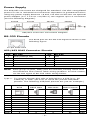
Power Supply
The A52/A53 converters are designed for standard +24 VDC unregulated
power for use in industrial environments. Operation is guaranteed when
using any power supply between +9 and +30 VDC at 350 mA. An optional
power adaptor (9 V 1.5 A UL 110/230 V) can support up to 4 converters
(see the following diagram).
A52/A53 Converter Connection Diagram
RS-232 Pinouts
10-pin RJ45 Jack
The RJ45 port for the RS-232 signal is shown in the
fo
llowing figure.
A52/A53 RJ45 Connector Pinouts
Pin
RS-232
Pin
RS-232
1
DCD (Always On)
6
RxD
2
DSR
7
GND
3
RTS
8
CTS
4
GND
9
DTR
5
TxD
10
–
NOTE
Each group of (DTR, DSR) pins are shorted, freeing users from
the hardware flow control cable wiring problem. For this reason,
we list two types of RS-232 cable wiring below.
Type 1:
To connect the RS-232 side of A52/A53 to a DTE (e.g., PC
COM1/2) or DCE. (B
e sure to check the precise DTE/DCE
pinouts. The following DTE/DCE pinouts are just an example.)
A52/A53
RJ45
DTE Device
DB25 Male
DTE Device
DB9 Male
DCE Device
DB25 Female
DCD
–
8
1
8
DCD
DSR
2
20
4
6
DTR
RTS
3
5
8
4
CTS
GND
4
7
5
7
GND
TxD
5
3
2
2
RxD
RxD
6
2
3
3
TxD
GND
7
7
5
7
GND
CTS
8
4
7
5
RTS
DTR
9
6
6
20
DSR

- 6 -
Type 2:
You can connect the RS-232 side of the A52/A53 to a DTE, such
as
a terminal or PC COM1/2, with 3-pin wiring if you don’t
need
hardware flow control.
A52/A53
RJ45
DTE Device
DB25 Male
DTE Device
DB9 Male
DCE Device
DB25 Female
TxD
5
3
2
2
RxD
RxD
6
2
3
3
TxD
GND
7
7
5
7
GND
RS-422/RS-485 Pinouts
The RS-422/RS-485 port with RJ45 connector or Terminal Block
Connector is depicted as follows.
RS-422
Pin
RS-422 with RJ45
Pin
RS-422 with Terminal Block
1
TxD – (A)
1
TxD + (B)
2
RTS – (A)
2
TxD – (A)
3
RTS + (B)
3
RxD + (B)
4/7
SG
4
RxD – (A)
5
TxD + (B)
5
SG
6
RxD + (B)
6
Power GND
8
CTS + (B)
7
VCCA (9V)
9
CTS – (A)
–
–
10
RxD – (A)
–
–
NOTE
Pins 6 and 7 of the Terminal Block are for Power GND and Power
Input, which can be used instead of a power adaptor. Be careful
NOT
TO confuse RS-422/RS-485 GND with Power GND.
SG: Signal Ground
RS-485
Pin
RS-485 with RJ45
Pin
RS-485 with Terminal Block
1
Data – (A)
1
Data + (B)
4
SG
2
Data – (A)
5
Data + (B)
5
SG
7
SG
6
Power GND
–
–
7
VCCA 9 V
–
–
8
–
NOTE
Pins 6 and 7 of the Terminal Block are for Power GND and Power
Input, which can be used instead of a power adaptor. Be careful
NOT TO confuse RS
-422/RS-485 GND with Power GND.
SG: Signal Ground

- 7 -
CE
WARNING
This is a Class A product. In a
domestic environment, this product
may cause radio interference in which case
the user may be
required to take appropriate measures.
Federal Communications Commission Statement
FCC - This device complies with part 15 of the FCC Rules. Operation is
subject to the following two conditions:
(1) This device may not cause harmful interference, and (2) this device
must accept any interference received, including interference that may
cause undesired operation.
FCC
WARNING
This equipment has been tested and found to comply with the
limits for a Class A digital device, pursuant to
part 15 of the FCC
Rules. These limits are designed to provide reasonable protection
against harmful
interference when the equipment is operated in
a
commercial environment. This equipment generates, uses,
and
can radiate radio frequency energy and, if not installed and used
in accordance with the instruction
manual, may cause harmful
interference to radio communications. Operation of this
equipment
in a residential area is likely to cause harmful
interference in which case the user will be required to correct the
interference at his own expense..
-
 1
1
-
 2
2
-
 3
3
-
 4
4
-
 5
5
-
 6
6
-
 7
7


Moxa Transio A52/A53 Series Quick setup guide
- Type
- Quick setup guide
Ask a question and I''ll find the answer in the document
Finding information in a document is now easier with AI
Related papers
-
 Moxa Technologies Transio A52/A53 Series Quick Install Guide
-
Moxa A53-DB25F User manual
-
Moxa A53/DB25 EU Datasheet
-
Moxa CP-114I-DB9M User manual
-
Moxa NPORT 5610-16 User manual
-
Moxa CP-134EL-A-I Series User manual
-
-
-
Moxa CP-134U-T User manual
-
Moxa NPORT 5610-8-DT-J Datasheet

Other documents
-
Panasonic TV Cables et-adser User manual
-
 Hexin Technology HXSP-485C User manual
-
Black Box IC237A User manual
-
Satec RSC232 User manual
-
 Moxa Technologies DE-304 User manual
-
Omega IC-11 Series Owner's manual
-
-
Lava A52 User manual
-
Advantech BB-422PP9R Quick start guide
-
 Moxa Technologies CP-114 Series User manual


