Page is loading ...

Installation & User Guide
Auralex
®
Acoustics, Inc.
1-800-959-3343 | 317-842-2600 | Auralex.com
9955 Westpoint Drive, Suite 101, Indianapolis IN USA 46256
MAX Kits
™
1694-618.MAX Kits User Guide (03/05/2020 - 1:18 PM)
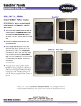
➍ ProMAX v2 only: Orient the foam side towards you to absorb acoustical
reflections. Position the angled / reflective side of the
ProMAX v2 facing you to redirect acoustical energy relative to your
listening position to achieve the desired effect.
When using the reflective side the panel’s overall angle can be adjusted
by rotating it on the stand. When using multiple pairs of ProMAX v2s
flanking the listening position, orient the angled reflective surfaces in
the same manner for a
balanced image and
soundstage.
To reverse the orientation of
the angled surfaces swap the
panel positions from one side
of the listening position to the
other.
Thank you for purchasing an Auralex
®
MAX Kit
™
Portable Treatment Kit.
VoxMAX
™
EditMAX
™
ProducerMAX
™
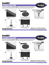
➌ Insert tube into the hole in the
center of the DeskMAX/ProMAX
v2 panel. This is best accomplished
by raising the panel over the top of
the stand pole and aligning it with
the hole in the panel. Gently pull the
panel down the pole to the desired
height. If the ceiling is low tilting
the stand and using assistance is
recommended.
➋ Remove star washer if present.
➊ Set up the stand and firmly
tighten the pole into the base.
Extent the top tube and firmly
tighten the adjustment collar.
DeskMAX
™
/ ProMAX v2
™
Setup
VoxMAX
™
Kit: Designed for Voice-Over/
Vocal recording and easy-to-use instrument or
microphone baffling. The Auralex
®
VoxMAX
Kit
™
can also be quickly positioned to address
reflections within a small recording, monitoring
or mixing environment.
EditMAX
™
Kit: Designed as an easily-
configured baffling solution for recording but
can also be quickly positioned to create an
accurate monitoring environment for editing and
mixing in spaces where permanently mounted
acoustical treatments are not desired.
ProducerMAX
™
Kit: A comprehensive and
easily-configured acoustical treatment solution
for recording. The Auralex ProducerMAX Kit
can be quickly positioned to create an accurate
monitoring and mixing environment in spaces
that do not permit permanently mounted
acoustical treatments.
DeskMAX
™
ProMAX
™
v2
ProMAX
™
v2 Front ProMAX
™
v2 Back

Installation & User Guide Installation & User Guide
Stand-Mounted LENRD
®
/ Studio6
™
Setup
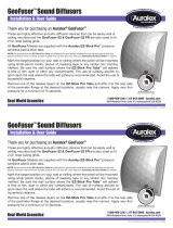
➍ Insert tube into the hole in the
center of the Stand-Mounted
LENRD or Studio6. This is best
accomplished with the panel
lying flat on a table or the floor.
Assistance is recommended.
➌ Place the LENRDs on a flat
surface, open up the center cut
on the rear and carefully pull out
the foam tube to open up the
stand hole. Place the Studio6
mid-line, face down on the edge
of a long counter top or table.
Flex the panel to open the rear
seam and remove the foam tube.
➎ Orient the wedge profile side of the LENRD
toward the listening space with the smooth
side near or flush into a corner for best
low frequency absorption. The height of
the LENRD Bass Trap can be adjusted as
needed. Optimal low frequency absorption
typically occurs when the LENRD is high
on the stand near the trihedral wall ceiling
corner. The Studio6 can be used as a bass
trap by placing the large bevels to the rear
and bridging the corner. It can also be
placed flat against the rear or side walls of
the room as needed.
➋ Remove star washer from the
top of the stand.
➊ Set up the stand and firmly
tighten the pole into the base.
Extent the top tube and firmly
tighten the adjustment collar.
2’ & 4’ Stand-Mounted LENRD
®
MoPAD-XL
™
ProPAD
™
Close up of a Studio6
™
after foam core removalStudio6
™
Removing the foam core from a LENRD
®
MoPAD-XL
™
/ ProPAD
™
Setup
Their ability to dramatically improve the resolution of your monitors is remarkable! By isolating your speakers from structural resonances
you will experience decreased coloration and increased clarity resulting in a sharper sound image.
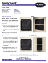
➊ Determine your monitors
location in your room following
the manufacturer’s placement
guidelines.
➋ Place your speakers on top of the
MoPAD-XLs or ProPADs with or
without the accessory wedges.
The wedge adjusters can be
oriented to achieve additional
down tilt, up tilt or a flat stance.
Down 8° Down 4° Flat Up 4° Up 8°
Down 2.5° Flat Up 2.5°

Installation & User Guide
MudGuard
™
v2 Setup
The MudGuard v2 is a flexible and cost effective method to control unwanted
acoustic reflections when recording vocal tracks in under treated rooms. This
user guide describes how to configure the included hardware to accommodate
various types of microphones and stands to maximum advantage.
Assembly Overview & Pointers
The hardware included with the MudGuard v2 enable it to be configured
with a wide variety of microphones and stands. The goal is to recess the
microphone diaphragm as far into the MudGuard v2 as possible and with the
pick-up diaphragm centered vertically for optimal isolation (see illustrations on
below).
• Use the extension tube to raise the height of the mic if it is too low or if clearance
between the mounting bar and the XLR connector and cable are needed.
• The thread adapter can be used to attach the MudGuard v2 to the mic stand separately from the microphone mount itself. This can help to
optimize the microphone position in the shell if required. The knob with the male mic stand threads is used to attach the mic and extension tube (if
required) to the MudGuard v2’s slotted mounting bar.
• A typical size microphone cable XLR connector can be fed through the wide circular area at the back of the mounting bar to optimize
the positioning of the microphone.
• For the most neutral tonal balance avoid placing the microphone near the back of the shell. Optimal results will be obtained with microphone
placements in the front third of the MudGuard v2s depth.
Mounting Hardware Configurations
Direct Mounting:
• The MudGuard v2 mounting bar, microphone and
extension tube (if required) can be attached directly to the
top of the mic stand using a star nut and a flat washer as
shown in Figure 1.
Indirect Mounting:
• The MudGuard v2 shield may be mounted to the mic
stand independently from the microphone and extension
tube using the male mic thread knob and threaded adapter
as shown in Figure 2.
Inverted mounting to a boom stand using a down tube is
accomplished using the same method and hardware as as
shown in Figure 2.
Male Mic
Thread Knob
3” Extension
Tube
Flat
Washers
Star
Nut
Threaded
Adapter
Included Hardware:
MudGuard v2
Microphone Shield
NOTE: Microphones and Stands Not Included
Figure 1 Figure 2

Auralex
®
Acoustics, Inc.
1-800-959-3343 | 317-842-2600 | Auralex.com
9955 Westpoint Drive, Suite 101, Indianapolis IN USA 46256
Installation & User Guide
/


