Page is loading ...

Trimmer/Brushcutter
Instruction Manual - RBS1226
Read and follow the operating instructions and safety information
before using for the first time.
Specifications subject to change without notice.
BRUSHCUTTER MUST BE
USED WITH CORRECT
SAFE GUARDING
Not for
Reproduction

2
IMPORTANTNOTES
T
Thank you for purchasing your VICTA trimmer & Brushcutter. VICTA prides itself in the
quality and performance of all its products.
This instruction manual will aid in the assembly, safe operation and maintenance of your
unit.
Please read the following warnings to ensure safety and the long life of your product.
General safety regulations
Warning!
Always switch off the
machine and pull off the
spark plug boot
Warning - Throughout this
manual specific attention is
required for your safety for care
and use of the product as a
brushcutter
Read the directions
before carrying out any
maintenance work.
Read the directions
for use before
operating the machine.
Be careful of objects being
thrown out!
Wear safety goggles,
a helmet and ear
protection.
All bystanders must be
kept at least 15 m from the
machine.
Wear sturdy, non-slip
footwear.
Tool continues to run some
seconds after switching off
motor.
Wear safety gloves. CAUTION: Hot machine
parts. Keep your distance.
Protect the machine
from rain and damp.
Please read the following
Always use correct
safety guarding
Not for
Reproduction

3
Table of Contents
n
g
h
e
m
e
o
ff
e
.
Features & Definitions
Feature Definitions 4
Safety & Handling
Safety Instructions 6
Hazards 8
Personal Safety Equipment 8
Assembly Procedures
Cast Trimmer Head 9
Fitting Brushcutter blade 10
Handles 13
Shoulder Strap 14
Operating Instructions
Fuelling Procedures 15
Starting Instructions 16
Stopping Instructions 18
Cutting Techniques 18
Maintenance & Care
Routine Maintenance 20
Storage 23
Maintenance 24
Troubleshooting
Troubleshooting 25
Technical specifications
Model Details 26
VICTA Products
Accessories & Spare Parts 27
Warranty
Warranty 28
Not for
Reproduction

4
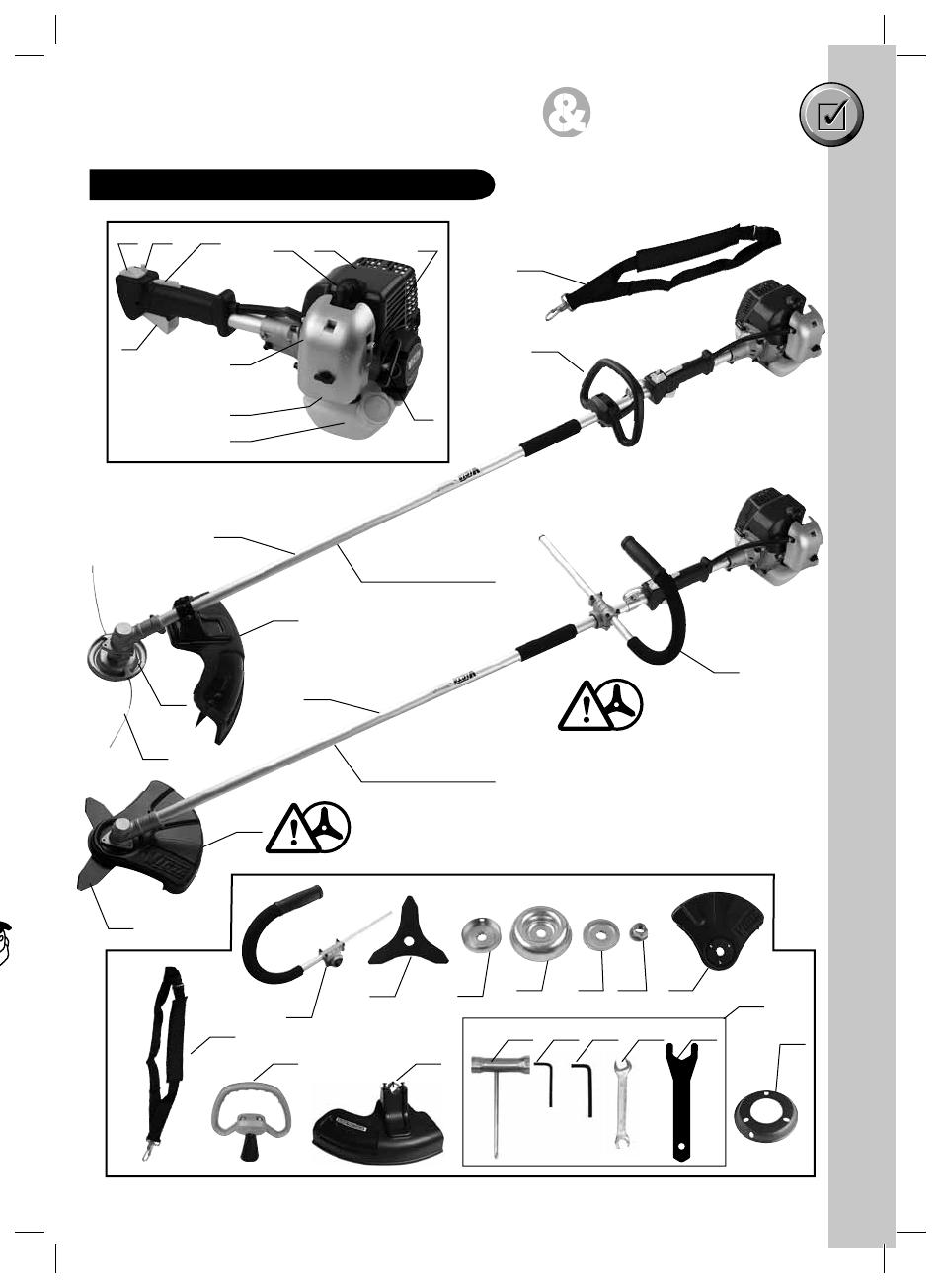
Machine Layout & Supplied Items
T
1 Cast trimmer head
2 3mmØ Nylon line
3 Trimmer line fillament guard
4 Solid straight shaft
5 Trimmer line fillament handle
6 Engine stop switch
7 Throttle lever "release"
8 Throttle lever
9 Throttle lever "lock"
10 Choke lever
11 Starter cord
12 Spark plug boot
13 Air filter housing cover
14 Petrol tank
15 Cowling
16 Fuel pump "primer"
17 Shoulder strap
18 Tools: a) Spark plug wrench,
b) Allen key 4mm,
c) Allen key 5mm,
d) Open spanner
e) Large open spanner
19 Trimmer flange
20 'Brushcutter safety J-handle (this MUST be in
place when using the Brushcutter blade)
21 Brushcutter blade (3T 10in 2.5mm)
22 Mounting washer
23 Brushcutter nut protector
24 Straight shaft washer
25 Straight shaft nut
26 Brushcutter guard 10in (this MUST be in place
when using the Brushcutter blade)
Do not operate the VICTA Trimmer/
Brushcutter before reading all
Safety & Handling sections.
&%!452%3 $%&).)4)/.3
Not for
Reproduction
5
Trimmer/Brushcutter Parts Description
5
3
26
4
4
697
813
16
14
10
11
1512
17 20
21 22 23 24 25 26
5 3
&%!452%3 $%&).)4)/.3
2
21
1
17
20
Must be in place
when using
Brushcutter blade
Must be in place when
using Brushcutter blade
Trimmer
configuration
Brushcutter
configuration
19
18
cba de
Not for
Reproduction

6
Safety Instructions
3!&%49 HANDLING
St
a
•
S
•
E
w
Cu
t
•
U
•
K
e
•
K
•
K
•
K
s
•
K
•
D
M
a
•
S
w
•
S
a
•
U
b
•
U
Tr
a
•
A
u
u
•
C
t
c
•
H
•
A
t
•
E
•
S
m
•
S
Do not operate the VICTA Trimmer/Brushcutter before reading all
Safety & Handling sections.
Operator Safety
• Wear the necessary safety equipment, as listed on page (12), in Personal Safety
Equipment.
• Always wear heavy, long pants. Do not wear loose clothing, jewellery, short pants,
sandals or go barefoot. Secure hair so it is above shoulder length.
• Do not operate the unit if you are tired, ill or under the influence of alcohol, drugs or
medication.
Unit Safety
• Inspect the entire unit and cutting head before each use.
• Ensure that the guard is properly attached.
• Do not use the unit if it is running erratically. Have it serviced promptly.
• Keep handles free of oil and fuel.
• Learn how to stop the engine quickly in an emergency.
• Stop the engine when the unit is unattended, even for a moment.
• Never allow children or unauthorised persons to operate the unit.
• Do not leave the unit on dry cuttings when it is Hot, as a risk of fire is present.
• Do not cover muffler or restrict airflow to muffler.
• When using the Brushcutter configuration, you must use the "J" Handle & Blade guard
(shown as item 23 & 28 on page 5).
• Do not touch the muffler or exhaust - Danger of burns.
• Always use in dry conditions on secure ground. Never risk safety by walking/climbing/
stepping/jumping on or over gaps, creeks, railings, fences with the unit or use on
unstable earth footing - check work area before using.
Fuel Safety
• Use a container approved for fuel and a funnel to avoid spillage.
• Mix and pour fuel outdoors where there are no sparks or flames.
• Frequently check for fuel leaks and clean carbon from the muffler at exhaust outlet.
• Do not smoke or allow smoking near fuel, or near the unit, or while using the unit.
• Add fuel before starting the unit.
• Never remove the fuel tank cap while the engine is running or hot, allow to cool before
refuelling.
• Never allow the unit to run out of fuel before refuelling.
• Move at least three metres away from the fuelling site before starting the engine.
• Wipe all traces of fuel on the unit before starting the engine.
• Change your clothes before stating the unit if fuel has been spilt on them.
Always ensure the unit is assembled in the correct configuration -
failure to do so will compromise your safety and others.
Not for
Reproduction

7
3!&%49 HANDLING
Starting Safety
• Start the engine with feet well away from the cutting head.
• Ensure that the area of starting and operation is clear of sticks, stones, glass, nails,
wire, string and debris, which could be thrown by the cutting head.
Cutting Safety
• Use only in good visibility and favourable weather conditions.
• Keep children, animals and bystanders outside the 15 metre hazard zone. Stop the
engine immediately if approached.
• Keep the engine to the right of your body, holding the unit with both hands.
• Keep a firm footing and balance. Do not over reach.
• Keep the cutting head below waist level and do not raise the engine above your
shoulder as the cutting head can come dangerously close to your body.
• Keep your body away from the cutting head and muffler when the unit is running.
• Do not strike objects that may cause harm or damage to the unit.
Maintenance Safety
• Stop the engine and disconnect the spark plug before clearing blockages, checking or
working on the unit.
• Stop the engine, disconnect the spark plug and inspect the unit if it begins to vibrate
abnormally or if it strikes a foreign object.
• Use only genuine VICTA trimmer line and genuine VICTA Brushcutter replacement
blade. Never use wire, rope, string, or any other blade, etc.
• Use only genuine VICTA replacement parts.
Transporting and Storage
• Always secure the unit when storing vertically - never leave the unit stored, resting
unsecured or unattended in the vertical position. Risk of falling causes damage to the
unit or property.
• Care is required for the handling and transport of the Brushcutter unit. Always carry
the Brushcutter horizontally. Ensure the blade is well clear of people and property. Poor
care handling can result in injury or damage to property.
• Hand carry the unit with the engine stopped, the muffler away from your body.
• Allow the engine to cool, empty the fuel tank and secure the unit before storing or
transporting in a vehicle.
• Empty the fuel tank after each use and before storing the unit.
• Store the unit and fuel well away from sparks or open flames from water heaters, electric
motors, switches or furnaces, etc.
• Store the unit out of reach of children and unauthorised persons.
d
/
e
Not for
Reproduction

8
3!&%49 HANDLING
F
1
2
3
S
1
2
3
4
5
6
Hazards
Personal Safety Equipment
Always use the following safety equipment when working with your trimmer:
• A safety helmet fitted with a visor or suitable eye protection.
• A set of ear muffs.
• A pair of protective gloves.
• A pair of safety boots.
The following safety precautions must be strictly observed to avoid the risk of damage or
personal injury.
Prior to using the unit, clear the operating area of objects which may
be thrown up by the cutting head, such as rocks, glass and other
debris.
Do not start or operate the unit inside a closed room or building.
Breathing exhaust fumes can kill.
Be careful when operating the unit on slippery ground or overgrown
terrain. Be attentive for concealed hazards, such as ditches, tree
stumps and roots.
Maintain solid footing and balance while operating the unit. Cut only
on ground level.
Never use the unit without the guard securely in place.
Do not touch the cutting head or blade in motion. When handling
blades for assembly or maintenance tasks, always wear protective
gloves.
Bystanders must be at least 15 metres away during operation of
the unit (fig 1), as rocks and other materials may be thrown at high
velocities. Switch the unit off immediately if approached.
Keep body away from hot muffler parts.
When using the Brushcutter configuration of the unit - you must use
the correct safeguards (refer to page 5 items 22 and 28)
F
B
Not for
Reproduction
9
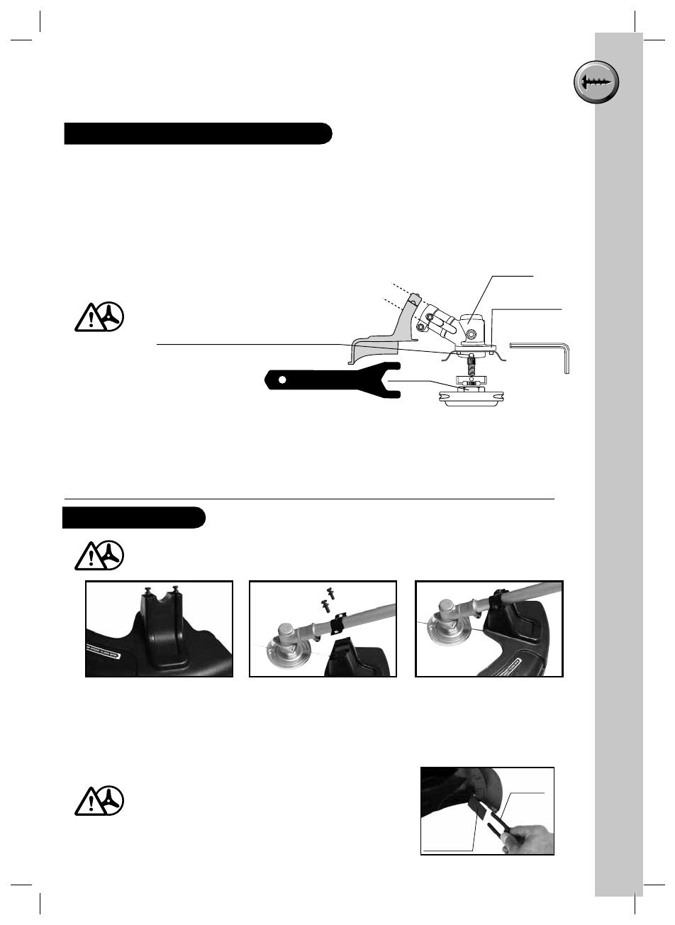
ASSEMBLYPROCEDURES
Make sure the guard is located on the housing before securing in position.
Fitting the straight shaft guard
1. Remove two screws from guard (Fig 1).
2. Position guard under the securing saddle (Fig 2).
3, Secure the two screws into the guard (Fig 3).
STRAIGHT SHAFT
1. Replace blade protector.
2. Align hole in flage and housing.
3. Insert Allen Key (supplied) into hole in flange and housing.
4. Grip the cast head and rotate clockwise to remove.
5. If cast head is too tight, use spanner supplied as
shown in diagram.
6. Refitting is in reverse order.
Blade in guard should be covered.
Always disconnect spark plug H.T.
lead before any work is done on the
trimmer.
NOTE: Not aligning the flange to the housing hole will cause damage.
Trimmer nylon line will deteriorate/with time resulting in more frequent
line breakages.
r
y
Trimmer Flange
Housing
Allen Key
Key hole to lock rotation
(NOTE: Align housing slot with key hole )
Fitting Trimmer Parts Description
Before Assembly
Fig: 1 Fig: 2 Fig: 3
Line cutting
blade
Blade
protector
A blade on the underside of the guard hood
automatically cuts the cutting line to the
optimum length. This is covered by a guard.
Remove the guard before you start working
and replace it when you have finished working.
Not for
Reproduction
10
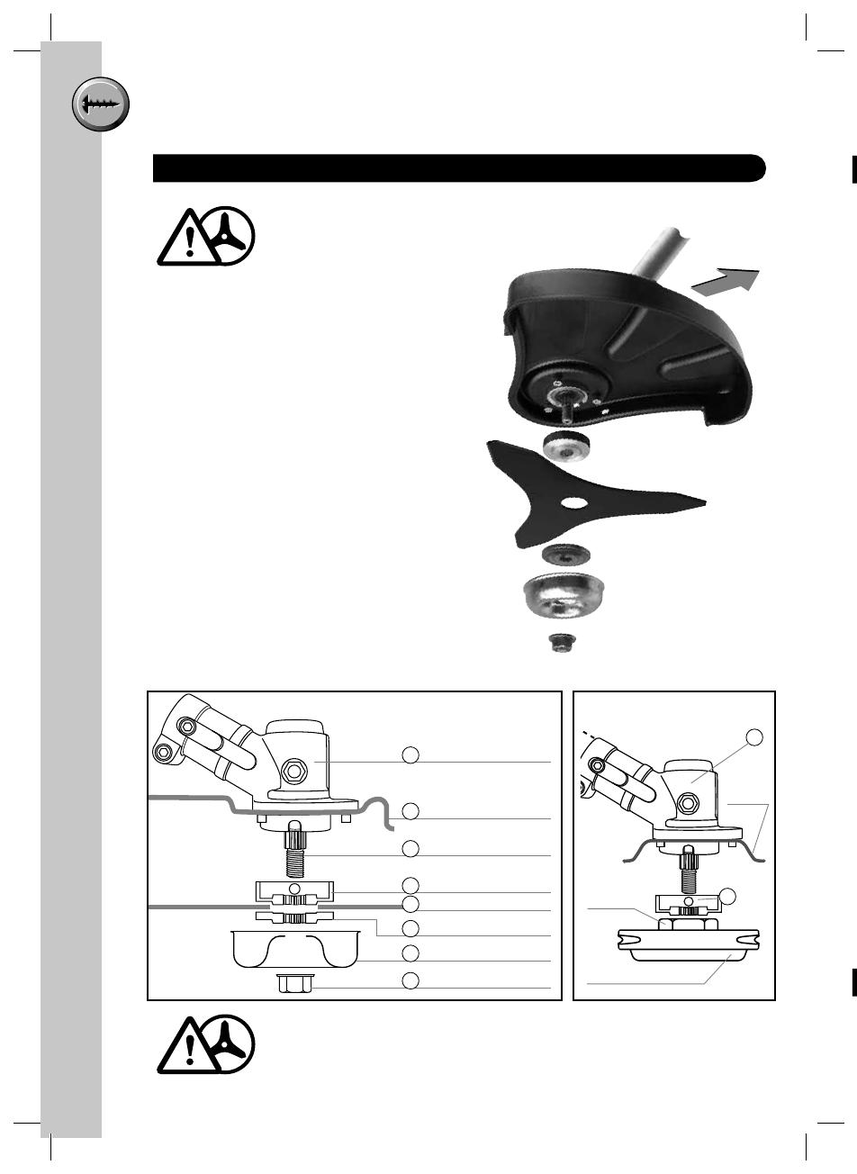
ASSEMBLYPROCEDURES
Fitting Brushcutter blade
(1) Insert Allen key through trimmer flange
& mounting washer into drive shaft
hole to lock the drive shaft, rotate the
Trimmer head clock wise (while viewed
from underneath) to remove.
If cast head is too tight use spanner
supplied (as shown in diagram)
(2) Remove the trimmer flange with Allen
key by unscrewing the 5mm bolts.
(3) Using the Allen key and three 5mm
bolts, secure the guard with (refer to
photograph for position of guard).
(4) Then place the mounting washer (4),
brushcutter blade (5), straight shaft
washer (6), nut protector (7) and
securing nut (8). While using the Allen
key again to lock the drive shaft tighten
the securing nut with the box spanner.
(5) Before starting the engine, make sure
that you also fit the "J" handle (refer to
page 13).
DAMAGED BLADE WILL CAUSE VIBRATION, AND MUST BE REPLACED
Gear box
10in Brushcutter guard
Drive shaft with spline
Mounting washer
Brushcutter blade
Straight shaft washer
Nut protector
Securing nut
1
Trimmer
Flange
Cast-Trimming Head
Use large
open spanner
here 4
2
1
3
4
5
6
7
8
Towards
operator
You must also fit the Brushcutter
safety J Handle
Brushcutter configuration Trimmer configuration
Not for
Reproduction

11
ASSEMBLYPROCEDURES
(1) Cut a length of line to 44cm, or use Victa part number TR00200A. Bend it in half
(equal ends). Use only 3mm diameter Nylon line (Fig: 1)
(2) Push the bent end of the line under the lug of the trimmer head
(3) Push one end of the line into the hole on the same side of the head as the line end.
Pull the line through the hole until loops or slack between the hole and centre lug is
removed.
(4) Repeat step 3 for opposite side. (5) Refer to image for correct complete assembly of
the nylon line into the head.
(6) To remove used line, bend new line as in (1), slide new line under used line through
slot in cast head.
(7) Holding both ends of the new line together, pull the old line out of the cast head.
Repeat process for the other side (8).
Fitting Trimmer Line
Removing Trimmer Line
4
3
7 8
21
Bend middle
5 6
Slot in
cast
head
1
m
er
g
e
d
s
o
r
Not for
Reproduction
12
ASSEMBLYPROCEDURES
U
F
(
(
(
(
(
Only use genuine VICTA 3mm diameter nylon trimmer line.
Always trim with the correct length of nylon line.
Always ensure that all components are firmly fastened before
starting any operation.
Unequal lengths will cause vibration and damage to unit.
Excessive trimmer line length will damage guard and clutch.
Replace line when 50mm from trimmer head body
Remove used line by pushing back into trimmer head or by levering
out.
Fitting Trimmer Line
"
F
1
2
3
4
N
Not for
Reproduction
13
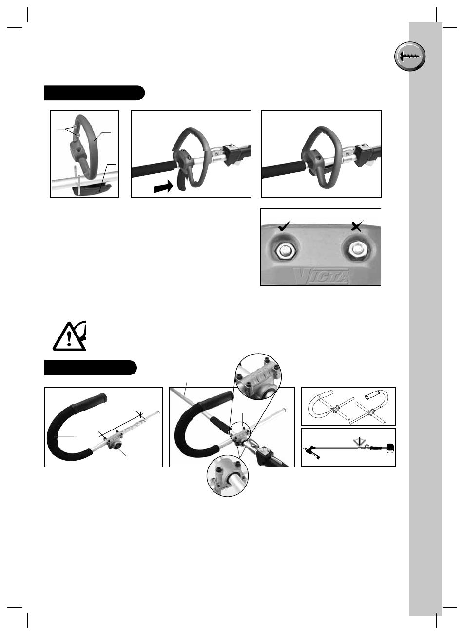
ASSEMBLYPROCEDURES
Universal Handle
Correct Wrong
2
1
3
Fitting the handle
(1) Components - 2 nuts, 'D' Grip Handle, Toggle
handle and 'U' Bolt.
(2) Place Universal Handle (2) over shaft.
(3) Insert Toggle Handle (3) around shaft and into
holes in Universal Handle.
(4) Screw on nuts (1) onto threads of 'U' Bolt by
fingers only, with toggle in open position.
(5) Be sure only to thread nuts (1) down so the
Toggle Handle has enough grip onto the shaft,
when levered into the close position.
Not too loose or too tight. Over tightening may damage the unit.
Toggle open position Toggle closed position
"J" Handle
Fitting the "J" handle
1 Remove the Universal handle.
2 Remove the underside bolts with the Allen key and separate the mounting clamp.
Keep the rubber seals in place.
3. Position grip on the main shaft and secure the bottom half of the mounting clamp with
the underside bolts.
4. Adjust and tilt the handle positionas desired by loosening the topside bolts. Keep the
handle positioned so that the mounting clamp is fixed between the two marks on the
handle.
NOTE: Handle can be fitted for R.H. or L.H. application (fig C) depending on operator
preference, the angle is also variable (fig D).
Adjustment
area
Bottom Bolts
Main Shaft
Top Bolts
Grip
Mounting
Clamp
AB
C
D
Not for
Reproduction

14
ASSEMBLYPROCEDURES
Fitting the carrying strap
• The strap is intended to help you work safely and ergonomically with the petrol grass
trimmer.
• Hook the strap into the fastening eyelet.
• Slip the strap over the shoulder.
• Set the length of the shoulder strap in such a way that the trimmer head runs parallel
to the ground. In order to establish the optimum length of the strap, you should then
make a few swinging movements without starting the engine.
B
Before Assembly
C
h
•
•
•
Fu
R
e
•
•
•
•
•
F
u
5
M
5
M
Not for
Reproduction

15
OPERATINGINSTRUCTIONS
s
s
el
n
Before Starting Machine
Check that all moving parts move smoothly before you start using the
machine. Check that all screws are securely fastened and also check all the
safety devices.
Always use the shoulder strap when using the appliance. Attach the strap
as soon as you have started the engine and the engine is running in idle
mode. Switch off the engine before you take off the shoulder strap.
Plan your job, never rush, take rest breaks and safety first always.
Check the machine for the following each time before use:
• That there are no leaks in the fuel system
• That the cutting unit and all safety devices are in perfect condition
• That all screws are securely fastened
Fuel and oil
Recommended fuels
• Use only a mixture of normal unleaded petrol and 2-stroke engine oil. Mix the fuel
mixture as indicated on the fuel mixing table.
• Start the machine at least 3 m away from the refuelling site to avoid the possible risk
of fire.
• Do not smoke whilst refuelling or working with the machine.
• Do not use the trimmer near inflammable liquids or gases. This could result in an
explosion and/or fire.
Do not use a fuel mixture which has been kept for longer than 90
days.
Do not use 2-stroke oil other than the recommended mixing ration
of 25:1. If inadequate lubrication causes engine damage, the
manufacturer's engine warranty will be voided.
Only use containers designed and approved for the purpose to
transport and store fuel.
• Pour the correct quantities of petrol and 2-stroke oil into a container. Then shake the
container well.
Fuel mixture table
Petrol (unleaded) 2-stroke oil
5 litre 200 ml
Mixing procedure: 25 parts petrol to 1 part oil
5 litre 100 ml (only with Victa Formula V 2 Stroke Oil)
Mixing procedure: 50 parts petrol to 1 part oil
Not for
Reproduction

16
OPERATINGINSTRUCTIONS
Starting the engine when cold
Fill the tank with the required amount of oil/petrol mix. See Fuel and oil.
(1) Set the machine down on a hard, level surface.
(2) Set the choke lever. ( )
(3) Press the fuel pump (primer) 10 times (this is found under the air filter housing).
(4) Ensure the 'STOP SWITCH' is set to the 'ON' position.
(5) To secure throttle lever:
a. Press throttle release (1)
b. Press throttle lever (2)
c. Press throttle lock (3)
d. Let go of the throttle release (1)
& throttle lever (2).
Note: By repressing the throttle lever this will
release the throttle lever from the locked position.
(6) Hold the machine firmly and pull out the starter until you feel it start to resist. Then
tug sharply on the starter 4 times. The machine should start.
Never allow the starter to snap back. This may damage the machine.
(7) Once the engine has started, move the choke lever immediately to ( ) and allow
the machine to warm up for approx. 10 seconds.
• If the engine does not start up, repeat steps 6-7 above.
O
Operation
PRIMER
1.
2.
3.
Choke
S
I
•
•
•
•
Not for
Reproduction

17
OPERATINGINSTRUCTIONS
w
Operation
Since the throttle lever is secured, the cutting tool starts to operate
when the engine is started. Release the throttle lock by simply pressing the
throttle lever (the engine then returns to running in idle mode).
If the engine does not start up even after several attempts, read the
section on Troubleshooting
Always pull the starter out in a straight line.
IF THIS IS NOT FOLLOWED, STARTER CORD WILL BE FRAYED
AND CORD WILL BREAK!
This is not covered by the Product Warranty.
Starting the engine when warm
If the machine has not been switched off for more than 15-20 minutes
• Set the machine down on a hard, level surface.
• Move the 'STOP' SWITCH to 'ON'.
• Secure the throttle lever (in the same way as described in Starting the engine when
cold).
• Hold the machine firmly and pull out the starter until you feel it start to resist. Then tug
sharply on the starter. The machine should start after 1-2 tugs. If the machine still fails
to start after 6 pulls, repeat steps 1-7 for starting the engine when cold.
Not for
Reproduction
18
OPERATINGINSTRUCTIONS
T
•
S
S
c
b
f
T
W
Emergency Stop procedure
• If it becomes necessary to stop the machine immediately. Let go of the throttle lever
and move the stop switch to 'OFF'.
Practical tips
• Practice all operating techniques with the engine switched off before you start to use
the machine.
DO NOT use steel wire or plastic-coated steel wire of any kind with
your stringhead. Serious operator injury can result.
Periodically remove weed wrap to prevent overheating the drive shaft.
Weed wrap occurs when strands of weed become entangled around
the shaft beneath the debris shield. This condition prevents the shaft
from being properly cooled.
• Stop engine – Remove spark plug H.T. lead from spark plug.
• Remove Weed/Grass wrapped around Head/Shaft.
Trimming Procedures
• When properly equipped with a guard and cutting head, your unit will trim
unsightly weeds and tall grass in those hard-to-reach areas – along fences,
walls, foundations and around trees. It can also be used for scalping to remove
vegetation down to the ground for easier preparation of a garden or to clean out a
particular area.
Even with care, trimming around foundations, brick or stone walls,
curves, etc. will result in above normal string wear.
Fence / Foundation Trimming
• Approach trimming around chain link fences, picket fences, rock walls and
foundations slowly to cut close without whipping string against the barrier. If the string
comes in contact with rock, brick walls, or foundations, it will break or fray. If string
snags fencing, it will snap off.
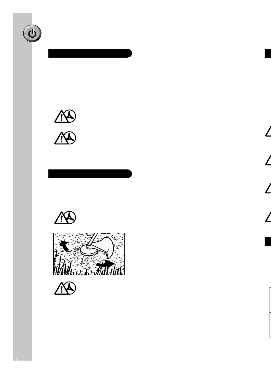
Switching Off the Engine
Trimming / Mowing
• Swing trimmer with a sickle-like motion from side
to side. Do not tilt the cutting head during the
procedure. Test area to be trimmed for proper
cutting height. Keep string head at same level
for even depth of cut.
Be aware of the trimmer head rotation.
Straight shaft = Anti-Clockwise
V
b
t
Not for
Reproduction
19
OPERATINGINSTRUCTIONS
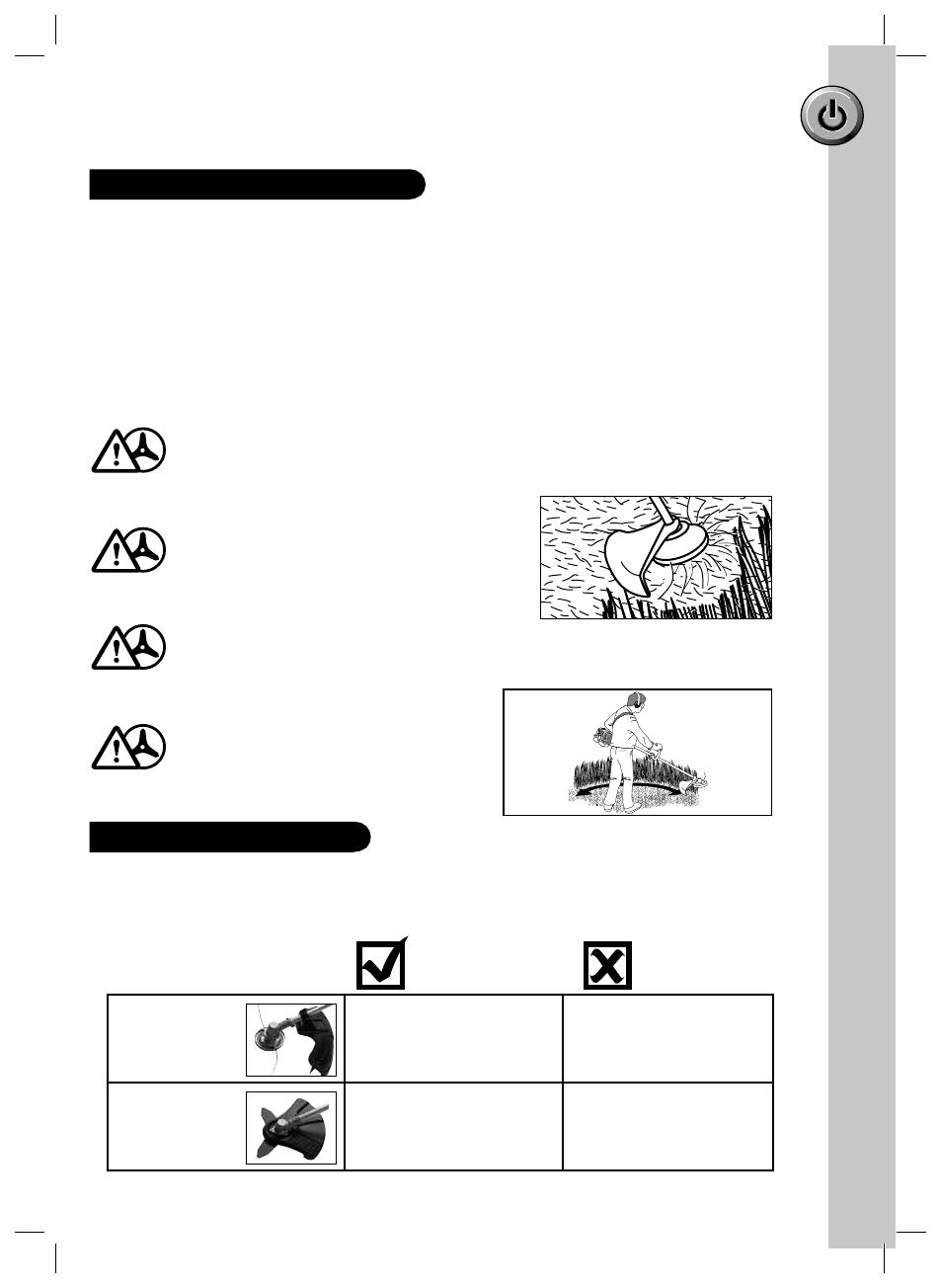
Attachment You may trim Do not trim
Grass Pasture
Nylon Head Lawn edges Shrubs
Borders Trees
Grass Lawn edges
Steel Blade Pasture Shrubs
Ferns, weeds, light growth Tress
Trimming Around Trees
• Trim around tree trunks with a slow approach so string does not contact bark. Walk
around the tree trimming from left to right. Approach grass or weeds with the tip of
the string and tilt cutting head slightly forward.
Scalping
Scalping refers to removal of all vegetation down to the ground. To do this, tilt the
cutting head to about 30 degree angle to the left. By adjusting the handle you will have
better control during this operation. Do not attempt this procedure if there is any chance
flying debris could injure operator, other people or cause damage to property.
Trimming Procedures continued
What can I trim or slash?
r
s
e
t
.
a
ng
i
de
r
l
Use extreme caution when SCALPING.
Keep a distance of 100 feet (30 metres)
between operator, other people and
animals during these operations.
Do not lift the cutting blade higher than waist height.
When trimming or brushcutting, use
in a side to side motion.
Take care with brushcutter - it is designed to remove foliage. Ensure
clearance to prevent inadvertant damage to healthy/wanted foliage.
VICTA Brushcutters trim and slash grass, weeds and pasture. Nylon heads and steel
blades are suitable for different operations, as listed below. Only use the particular
trimming attachment for the listed uses.
Trimmer
Brushcutter
Not for
Reproduction

20
Maintenance Chart
M
M
S
T
C
c
1
2
3
Maintenance
• Always switch off the machine and pull out of spark plug H.T. lead before carrying out
any maintenance work.
Maintenance of the air filter
Dirty air filters reduce the engine output by supply too little air to the carburettor.
Regular checks are therefore essential. The air filter should be checked monthly and
cleaned if necessary. If the air contains a lot of dust, the air filter should be checked
more frequently.
1. Remove the air filter cover
2. Remove the filter element
3. Clean the filter element by washing in soapy water and allowing it to dry completely.
4. Soak in a mixture of 25:1 2 stroke fuel and squeeze off excess.
5. Assemble in reverse order.
Never clean the air filter with petrol or inflammable solvents.
Make sure Air Filter is fitted correctly, (warranty will be void if engine
is damaged due to incorrect fitment)
Tongue
Location
Not for
Reproduction
/