Page is loading ...

THANK YOU FOR CHOOSING SANUS
THE #1 TV MOUNT BRAND IN THE US.
VST4
Instruction Manual

2
VST4
Lo haremos sin estrés
Si tiene preguntas mientras realiza la instalación, llámenos.
1-800-359-5520 (Reino Unido: 0800-056-2853) Estamos listos para ayudarlo.
We’ll Make It Stress-Free
If you have any questions along the way, just give us a call.
1-800-359-5520 (UK: 0800-056-2853) We’re ready to help!

3
IMPORTANT SAFETY INSTRUCTIONS – SAVE THESE INSTRUCTIONS – PLEASE READ ENTIRE MANUAL PRIOR TO USE
Before getting started, let’s make sure this mount is perfect for you!
No
—
Perfect!
Yes
—
This mount is NOT compatible. Visit MountFinder.Sanus.com or call
1-800-359-5520 (UK: 0800-056-2853) to find a compatible mount.
Please read through these instructions completely to be sure you’re comfortable with this easy install process.
Also check your TV owner’s manual to see if there are any special requirements for mounting your TV.
If you do not understand these instructions or have doubts about the safety of the installation, assembly or use
of this product, contact Customer Service at 1-800-359-5520 (UK: 0800-056-2853).
Do you have
all the tools
needed?
1
2
3
4
What is your
wall made of?
Unsure?
Drywall with
wood studs?
Solid concrete or
concrete block?
50 lbs
(22.7 kg)
CAUTION: Avoid potential personal injuries and property damage!
● This product includes directions and hardware for use with wood stud, solid concrete and concrete block walls –
DO NOT install into drywall alone.
● The wall must be capable of supporting five times the weight of the TV and mount combined.
● Do not use this product for any purpose not explicitly specified by manufacturer.
● Manufacturer is not responsible for damage or injury caused by incorrect assembly or use.
Call Customer Service:
1-800-359-5520 (UK: 0800-056-2853)
Perfect! Perfect!
Ready to
begin?
Does your TV weigh
more than 50 lbs
(22.7 kg) including
accessories?
7/16 in.
(12 mm)
1/8 in.
(3 mm)
Wood
Screwdriver
Tape
Measure
Drill Bit Drill Bit Electric Drill Hammer
Socket
Wrench
Pencil Wrench
3/8 in.
(10 mm)
Concrete
3/8 in.
(10 mm)
Awl
Stud
Finder
Level
Para Español ver página 17

4
STEP 1 Attach Bracket to TV
WARNING: This product contains small items that could be a choking hazard if swallowed.
Before starting assembly, verify all parts are included and undamaged. If any parts are missing or damaged, do not return the damaged
item to your dealer; contact Customer Service. Never use damaged parts!
Parts and Hardware for STEP 1
NOTE: Not all hardware included will be used.
*You may need to separate the TV
bracket
01
from the wall plate
18
before starting this step.
TV Bracket*
200 x 200 Extension
200 x 200 Extension Screw
200 x 200 Extension Nut
M4 x 12mm
M6 x 12mm M6 x 20mm M6 x 35mm
M8 x 16mm M8 x 35mm
1/4 x 2 ½ in.
M4 x 30mm
M4 x 12mm
M6 x 12mm M6 x 20mm M6 x 35mm
M8 x 16mm M8 x 35mm
1/4 x 2 ½ in.
M4 x 30mm
M4 x 12mm
M6 x 12mm M6 x 20mm M6 x 35mm
M8 x 16mm M8 x 35mm
1/4 x 2 ½ in.
M4 x 30mm
M6 x 14mm
02
x2
01
x1
03
x4
04
x4
01
01
18

5
WARNING: This product contains small items that could be a choking hazard if swallowed.
Before starting assembly, verify all parts are included and undamaged. If any parts are missing or damaged, do not return the damaged
item to your dealer; contact Customer Service. Never use damaged parts!
Parts and Hardware for STEP 1
NOTE: Not all hardware included will be used.
M4 M6/M8
M4 x 12mm
M6 x 12mm
M8 x 12mm
M4 x 30mm
M6 x 20mm M6 x 35mm
M8 x 35mm
M8 x 20mm
M4
M6/M8
05
x4
07
x4
10
x4
12
x4
11
x4
15
x8
16
x4
13
x4
14
x4
08
x4
09
x4
06
x4
TV Screws
TV Washers
TV Spacers

6
1-1 Select TV Screws
1-2 Spacers
Hand thread screws into the threaded inserts on the back of your TV
to determine which screw diameter (M4, M6, or M8) to use.
CAUTION: Verify adequate thread engagement of the screw/
spacer combination on your TV.
Too short will not hold the TV and too long will damage the TV.
M4
M6
M8
Too Short Correct Too Long
TV Bracket
TV Bracket
06
Round Back CablesInset HolesFlat Back
TV Bracket
A
A
B
B
Your TV type will help you determine which hardware
configuration to use. Match your type of TV to the suggested
hardware configuration on the next page.
A. Installation option without spacers (TVs with flat backs).
B. Installation option using spacers (TVs with obstructed backs
or inset mounting holes).
Standard configurations are shown. For special applications, or if you are
uncertain about your hardware selection, contact Customer Service at
1-800-359-5520
.

7
1-4 Attach Extensions (200 x 200 mm ONLY)1-3 Measure Your TV Hole Pattern
If mounting to a TV with a 200 x 200 mm (7 ⅞ x 7 ⅞ in.) hole pattern, add the extension plates
02
to the TV bracket
01
using the extension plate screws
03
and nuts
04
.
NOTE: Nuts
04
are poly-locks and will need to be forcibly tightened.
Measure the width and height of your
TV hole pattern in mm.
Record your measurements:
cm
inches
cm
inches
x Height
Width
mm mm
75 mm = 7.5 cm = 3 in.
100 mm = 10 cm = 4 in.
200 mm = 20 cm = 7 7/8 in.
inch dimensions approximate
02
01
04
03

8
Position the TV bracket
01
over your TV hole pattern and install using the screw, washer, and spacer (if needed) combination you selected for
your TV.
M6/M8 spacer, screw, and washer
15 16
0615
16
14
13 15
M4/M6/M8 screw and washer
M4 spacer, screw, and washers
1-5 Attach TV Bracket
NOTE: If the hole pattern
on your TV is 75 x 75 mm the
washer
15
will not be used.
05 07 08 10
11
09 12
01
200 x 200 mm 200 x 100 mm
100 x 100 mm
75 x 75 mm
01
01
01

9
STEP 2 Attach Wall Plate to Wall
Parts and Hardware for STEP 2
WARNING: This product contains small items that could be a choking hazard if swallowed. Before starting assembly, verify all parts are
included and undamaged. If any parts are missing or damaged, do not return the damaged item to your dealer; contact Customer Service. Never
use damaged parts!
17
x1
18
x1
Wall Plate
Wall Plate
Template
M4 M6/M8 M4 M6/M8
MED TV HARDWARE BAG 1
PPMSM4X12ZI02 4 M4 12mm
PPMSM4X30ZI02 4 M4 30mm
PPMSM6X12ZI02 4 M6 12mm
PPMSM6X20ZI02 4 M6 20mm
PPMSM6X35ZI02 4 M6 35mm
PPMSM8X16ZI02 4 M8 16mm
PPMSM8X35ZI02 4 M8 35mm
SPNY.500X.215X.649 BLACK 4 small spacer
SPNY.700X.335X.866 BLACK 4 Large spacer
SPZSM16.50X8.40X1.00ZI02 4 large washer
SPZSM16.50X5.40X1.50ZI02 8 small washer
MED LAG HARDWARE 1
SPZS.695X.350X.075BZ02 3 Washer
HHLS25X22BZ02 3 Lag bolt
Fischer UX10x60R, ANCHOR 3 Anchor
5/16 x 2¾ in.
M4 x 12mm
M8 x 16mm
M4 x 30mm
M8 x 35mm
M6 x 20mmM6 x 12mm M6 x 35mm
M6 x 14mmM6
F18 HARDWARE BAG 1
HHLS24X20Z1 2 1/4 x 2.5 in. lag
LNNYM6BZ 4 M6
PFMSM6X25BZ02 4 M6 x 25mm
F215 MISC HARDWARE BAG 1
PTMS0832X03ZI02 1
PTMS0832X4.5ZI02 4
3/16” S/A Hex Key 1
5/32” S/A Hex Key 1
8-32 x 9/16 in.8-32 x 3/8 in.
1/4 x 2.5 in.
5/32 in.
3/16 in.
¼ x 2½ in.
For wood stud installations, follow STEP 2A on PAGE 10
For concrete installations, follow STEP 2B on PAGE 12
NOTE: Not all hardware included will be used.
19
x2
Lag Bolts
20
x2
Concrete Anchors

10
STEP 2A
Wood Stud Option
CAUTION: Avoid potential per-
sonal injuries and property damage!
● Drywall covering the wall must not
exceed 5/8 in. (16 mm)
● Minimum wood stud size:
nominal 2 x 4 in. (51 x 102 mm)
actual 1½ x 3½ in. (38 x 89 mm)
● Stud center must be verified
1. Locate a nail/screw in the studs
using a stud finder.
2. Find the edges of the studs using
an awl.
3. Mark the centers of the studs with
a pencil.
1 2 3
Max. 5/8 in. (16 mm)
Min. 16 in. (406 mm)
Min. 3 1/2 in. (89 mm)
Min. 1 1/2 in. (38 mm)

11
4 5
6
63.5 mm
(2 1/2 in.)
3 mm
(1/8 in.)
17
17
18
4. Place the wall plate template
17
at your desired height and position the slotted holes over your stud center line. Level the wall plate tem-
plate
17
and tape in place.
NOTE: For assistance in determining wall plate location, see HeightFinder at sanus.com.
IMPORTANT: Be sure you mark and drill into the center of the stud.
5. Drill the two pilot holes using a 3 mm (1/8 in.) diameter drill bit.
IMPORTANT: Pilot holes must be drilled to a depth of 63.5 mm (2½ in.).
6. Remove the wall plate template
17
. Tighten lag bolts
19
only until they are pulled firmly against the wall plate
18
.
CAUTION: Improper use could reduce the holding power of the lag bolt. To avoid potential injuries or property damage do not over-
tighten the lag bolts
19
.
19

12
1
2
Solid Concrete or Concrete Block Option
CAUTION: Avoid potential personal injuries and property damage!
● Mount the arm assembly/wall plate
18
directly onto the concrete surface
● Minimum solid concrete thickness: 203 mm (8 in.)
● Minimum concrete block size: 203 x 203 x 406 mm (8 x 8 x 16 in.)
1. Position the wall plate template
17
on the wall at your desired height. Level the wall plate template and mark the hole locations.
NOTE: For assistance in determining wall plate location, see Height Finder at sanus.com.
2. Drill two pilot holes using a 10 mm (3/8 in.) diameter drill bit.
IMPORTANT: Pilot holes must be drilled to a depth of 75 mm (3 in.). Never drill into the mortar between blocks.
STEP 2B
002862.eps
10 mm
(3/8 in.)
75 mm
(3 in.)
17
17

13
3
20
4
3. Remove the wall plate template
17
and insert two anchors
20
.
CAUTION: Be sure the anchors
20
are seated flush with the concrete surface.
4. Tighten lag bolts
19
only until they are pulled firmly against the wall plate
18
.
CAUTION: Improper use could reduce the holding power of the lag bolt. To avoid potential injuries or property damage, do not over-
tighten the lag bolts
19
.
18
19

14
STEP 3 Attach TV to Wall Plate
18
01
HEAVY! You may need assistance with this step.
IMPORTANT: The locking tab needs to be in the unlocked position before attaching the TV to the wall plate.
Once the TV is on the wall plate, the locking tab needs to be in the locked position.

15
Troubleshooting
ADJUSTING THE TILT: Loosen the knob on the TV bracket to adjust
the tilt of your TV. Tighten the knob when your TV is set to the
desired tilt.
REMOVING THE TV: Place the locking tab into the unlocked
position and lift the TV up and out away from the wall plate.
01
01

16
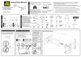
Dimensions
12°
1.78
45.2
7.87
200.0
0.35
8.8
7.87
200.0
3.94
100.0
3.94
100.0
7.50
190.5
0.34
8.8
0.22
5.5
8.69
220.7
2.95
75.0
2.95
75.0
5.25
133.3
ESPAÑOL

17
Antes de comenzar, verifiquemos que este soporte sea perfecto para usted.
ESPAÑOL
INSTRUCCIONES DE SEGURIDAD IMPORTANTES. CONSÉRVELAS. LEA TODO EL MANUAL ANTES DE
UTILIZAR ESTE PRODUCTO.
10 mm
(3/8")
3 mm
(1/8")
Madera
10 mm
(3/8")
Hormigón
No
—
¡Perfecto!
Sí
—
Este soporte NO es compatible. Visite MountFinder.Sanus.com o llame al
1-800-359-5520 (Reino Unido: 0800-056-2853) para encontrar un soporte compatible.
¿Su televisor pesa
más de 22,7 kg
(50 lbs), incluidos
los accesorios?
Lea estas instrucciones en su totalidad para estar seguro de sentirse cómodo con este fácil proceso de instalación. Consulte
también el manual del usuario de su televisor para ver si existe algún requisito especial para instalar su televisor en la pared.
Si no entiende las instrucciones o si tiene dudas acerca de la seguridad de la instalación, del ensamblado o del uso del
producto, póngase en contacto con el servicio de atención al cliente al 1-800-359-5520 (Reino Unido: 0800-056-2853).
¿Tiene
todas las
herramientas
necesarias?
1
2
3
4
¿De qué está
hecha su
pared?
¿No está
seguro?
¿Hormigón sólido
o bloques de
cemento?
22,7 kg
(50 lbs)
¿Listo para
comenzar?
12 mm
(7/16")
¿Tabiques
de yeso con
montantes de
madera?
Llame al 1-800-359-5520
(Reino Unido: 0800-056-2853)
¡Perfecto! ¡Perfecto!
Destornillador Cinta métrica Broca Broca Taladro eléctrico Martillo Llave de tubo
Llave inglesa
Lápiz
PRECAUCIÓN: Evite posibles lesiones personales y daños materiales.
● Este producto incluye instrucciones y elementos de sujeción para su instalación en paredes con montantes de madera,
en superficies de hormigón y sobre bloques de cemento. NO lo instale en tabiques únicamente de yeso.
● La pared debe soportar cinco veces el peso del televisor y del soporte juntos.
● No utilice este producto para ningún otro propósito que no sea el explícitamente especificado por el fabricante.
● El fabricante no se responsabiliza por ningún daño o lesión resultante del montaje incorrecto o de uso indebido.
Punzón
Localizador
de montantes
Nivel

18
ESPAÑOL
PASO 1 Fijar la placa de sujeción al televisor
Piezas y elementos de sujeción para el PASO 1
NOTA: No todos los accesorios incluidos deberán utilizarse.
ADVERTENCIA: Este producto contiene piezas pequeñas que, si fuesen tragadas, podrían producir asfixia. Antes de iniciar el ensamblaje,
compruebe que todas las piezas estén incluidas y en buenas condiciones. Si faltan piezas o alguna está dañada, no devuelva el artículo al
distribuidor; póngase en contacto con el servicio de atención al cliente. Nunca utilice piezas deterioradas.
1-1 Seleccione los tornillos para el televisor
Enrosque manualmente los tornillos en los encastres roscados del dorso del televisor a fin de determinar qué diámetro de tornillos
(M4, M6 o M8) utilizar.
1-2 Espaciadores
PRECAUCIÓN: Verifique que la combinación de tornillo y espaciador enrosque correctamente en su televisor.
Si el tornillo es demasiado corto, no sostendrá el televisor. Si es demasiado largo, dañará el televisor.
1-3 Mida el patrón de orificios de su televisor
1-4 Instale las extensiones (SOLAMENTE 200 x 200 mm)
El tipo de televisor le ayudará a determinar la configuración de elementos de sujeción que debe utilizar. Compruebe la configuración de
elementos de sujeción recomendada para su tipo de televisor en la página siguiente.
A. Opción de instalación sin espaciadores (televisores con dorso plano).
B. Opción de instalación con espaciadores (televisores con parte posterior con obstrucciones u orificios de montaje intercalados).
Se ilustran las configuraciones estándar. En caso de aplicaciones especiales, comuníquese con el Servicio de Atención al Cliente.
Mida en mm el ancho y el alto del patrón de orificios del televisor. Anote las medidas:
x Alto
Ancho
mm mm
Si va a instalar en un televisor con un patrón de orificios de 200 x 200 mm (7.87 x 7.87 pulgadas), incorpore las placas de extensión
02
a la placa
de sujeción para el televisor
01
usando los tornillos
03
y tuercas
04
para placas de extensión.
NOTA: Las tuercas
04
son del tipo Poly-lock y deberán ajustarse con fuerza.
*Es posible que necesite separar la placa de sujeción del televisor
01
de la placa mural
18
antes de comenzar este paso.

19
ESPAÑOL
PASO 2 Fijar la placa mural a la pared
ADVERTENCIA: Este producto contiene piezas pequeñas que, si fuesen tragadas, podrían producir asfixia.
Antes de iniciar el ensamblaje, compruebe que todas las piezas estén incluidas y en buenas condiciones. Si faltan piezas o alguna está dañada,
no devuelva el artículo al distribuidor; póngase en contacto con el servicio de atención al cliente. Nunca utilice piezas deterioradas.
Piezas y elementos de sujeción para el PASO 2
Ubique la placa de sujeción
01
sobre el patrón de orificios del televisor e instálela usando la selección de tornillo, arandela y espaciador (si fuera
necesario) que seleccionó para su televisor.
1-5 Coloque la placa de sujeción
NOTA: Si el patrón de orificios de su televisor de es 75 x 75 mm
15
no deberá utilizar la arandela.
Para instalaciones en pared con montantes de madera, siga el PASO 2A en la PÁGINA 10
Para instalaciones en pared de hormigón, siga el PASO 2B en la PÁGINA 12

20
PASO 2A
Opción para montantes de madera
ESPAÑOL
PRECAUCIÓN: Evite lesiones y daños materiales.
● El yeso que recubre la pared no debe exceder los 16 mm (5/8'').
● Tamaño mínimo del montante de madera: común 51 mm x 102 mm (2 x 4 pulgadas), nominal 38 mm x 89 mm (11/2 x 31/2 pulgadas).
● Debe verificarse el centro del montante
1. Localice un clavo / tornillo en los montantes con un buscador de montantes.
2. Encuentra los bordes de los montantes con un punzón.
3. Marque los centros de los postes con un lápiz.
4. Coloque la plantilla de placa mural
17
a la altura deseada y y posicione los orificios muescados sobre la línea del centro del
montante. Nivele la plantilla de placa mural
17
y fíjela con cinta adhesiva en el lugar.
NOTA: Si necesita ayuda para determinar la ubicación de la placa mural, utilice la herramienta HeightFinder disponible en sanus.com.
IMPORTANTE: Asegúrese de marcar y perforar el centro del montante.
5. Con una mecha de 3 mm (1/8'') de diámetro, realice dos orificios guía.
IMPORTANTE: Los orificios deben realizarse hasta una profundidad de 63.5 mm (2.5'').
6. Retire la plantilla de placa mural
17
. Ajuste los tornillos tirafondo
19
solamente hasta que queden firmes contra la placa mural
18
.
PRECAUCIÓN: El uso indebido podría reducir la capacidad de retención de los tornillos tirafondo. Para evitar lesiones y daños
materiales: no ajuste en exceso los tornillos tirafondo
19
.
/