990-1957A-001
4/2009
*990-1957A-
Installation
MGE™ Galaxy™
3500
10-30 kVA 208/220 V with batteries
IMPORTANT SAFETY INSTRUCTIONS
- SAVE THESE INSTRUCTIONS
Warning: ALL safety instructions in the Safety Sheet
(990-2940) must be read, understood and followed when
installing the UPS system. Failure to do so could result in
equipment damage, serious injury, or death.
Warning: After the UPS has been electrically wired, do
not start it up. Start-up is commissioned to authorized
personnel from Schneider Electric.
Caution: All electrical power and power control wiring
must be installed by a qualified electrician, and must comply
with local and national regulations for maximum power
rating.
Note: Ensure that the unit is in its final location prior to
installation.
Note: Battery and utility power must not be connected until
all other wiring has been completed.
See Also: For parallel configurations see manual 990-
3568.
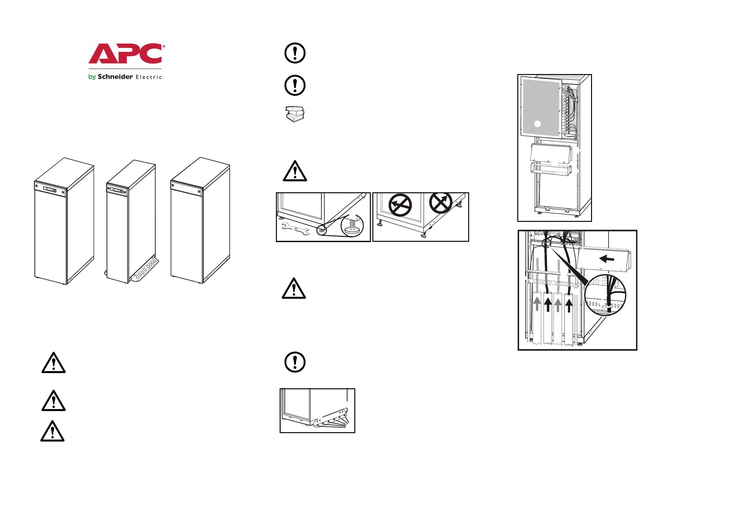
Level the Enclosure
Warning: The system must be installed on a level floor.
The leveling feet will stabilize the enclosure, but will not
account for a badly sloped floor.
Use a 13/14 mm wrench to adjust the four leveling feet.
Ensure that the system is level.
Caution: Do not move the enclosure after the leveling feet
have been lowered.
Floor Anchoring (if applicable)
Anchor the UPS enclosure to the floor
Note: Floor-anchoring bolts are not provided with the UPS.
Purchase the bolts locally (minimum size: M8). Follow the
specifications given by the manufacturer of the floor
anchoring system when bolting the UPS system to the floor.
Reuse the two transport brackets (one
on each side) that were used to secure the
UPS to the pallet during transport.
Drill two to six holes in the floor for
each bracket. Attach with bolts.
Prepare for Cables
Bottom cable entry
From the rear of the UPS, loosen the six
M4 screws from the upper cover (the cable
landing area), and remove. Save the screws
for later use.
Loosen the two M4 screws (one on each
side) from the top part of the conduit box.
Loosen the M4 screws attaching it to the
bottom part (two screws in a 352 mm (13.8
in) enclosure), (three screws in a 523 mm
(20.50 in) enclosure) and remove. Save the
screws for later use.
Loosen the four M4 screws (two on each
side) from the conduit box bottom and
remove. Save the screws for later use.
Punch as many holes as
needed in the marked areas
of the bottom conduit box.
Attach the conduit box
bottom to the enclosure
(reuse the screws from step
.
Attach conduits to the
conduit box.
Run the cables through
the conduits, the bottom of
the conduit box, and up into
the cable landing area.
Attach the conduit box top to the conduit box bottom, and to the
enclosure reusing the screws from step .
Fasten the cables with cable ties.
UPS
UPS
XR battery enclosure
Bypass
Output
Battery
Mains


