
1
Z75 Pro3
User Manual
Version 1.0
Published February 2012
Copyright©2012 ASRock INC. All rights reserved.

2
Copyright Notice:
No part of this manual may be reproduced, transcribed, transmitted, or translated in
any language, in any form or by any means, except duplication of documentation by
the purchaser for backup purpose, without written consent of ASRock Inc.
Products and corporate names appearing in this manual may or may not be regis-
tered trademarks or copyrights of their respective companies, and are used only for
identifi cation or explanation and to the owners’ benefi t, without intent to infringe.
Disclaimer:
Specifi cations and information contained in this manual are furnished for informa-
tional use only and subject to change without notice, and should not be constructed
as a commitment by ASRock. ASRock assumes no responsibility for any errors or
omissions that may appear in this manual.
With respect to the contents of this manual, ASRock does not provide warranty of
any kind, either expressed or implied, including but not limited to the implied warran-
ties or conditions of merchantability or fi tness for a particular purpose.
In no event shall ASRock, its directors, offi cers, employees, or agents be liable for
any indirect, special, incidental, or consequential damages (including damages for
loss of profi ts, loss of business, loss of data, interruption of business and the like),
even if ASRock has been advised of the possibility of such damages arising from
any defect or error in the manual or product.
This device complies with Part 15 of the FCC Rules. Operation is subject to the fol-
lowing two conditions:
(1) this device may not cause harmful interference, and
(2) this device must accept any interference received, including interference that
may cause undesired operation.
CALIFORNIA, USA ONLY
The Lithium battery adopted on this motherboard contains Perchlorate, a toxic
substance controlled in Perchlorate Best Management Practices (BMP) regulations
passed by the California Legislature. When you discard the Lithium battery in Cali-
fornia, USA, please follow the related regulations in advance.
“Perchlorate Material-special handling may apply, see
www.dtsc.ca.gov/hazardouswaste/perchlorate”
ASRock Website: http://www.asrock.com

3
Contents
1 Introduction ......................................................... 5
1.1 Package Contents ......................................................... 5
1.2 Specifi cations ................................................................. 6
1.3 Motherboard Layout ....................................................... 13
1.4 I/O
Panel ...................................................................... 14
2 Installation ........................................................... 16
2.1 Screw Holes ................................................................... 16
2.2 Pre-installation Precautions ......................................... 16
2.3 CPU Installation ............................................................. 17
2.4 Installation of Heatsink and CPU fan ............................. 19
2.5 Installation of Memory Modules (DIMM) ........................ 20
2.6 Expansion Slots
(PCI and PCI Express Slots)
.................... 22
2.7 CrossFireX
TM
and Quad CrossFireX
TM
Operation Guide 23
2.8 Dual Monitor and Surround Display Features ................ 27
2.9 ASRock Smart Remote Installation Guide ..................... 30
2.10 Jumpers Setup .......................................................... 31
2.11 Onboard Headers and Connectors ............................ 32
2.12 Serial ATA (SATA) / Serial ATA2 (SATA2) Hard Disks
Installation ................................................................. 37
2.13 Serial ATA3 (SATA3) Hard Disks Installation ............. 37
2.14 Hot Plug and Hot Swap Functions for SATA / SATA2
HDDs ............................................................................ 38
2.15 Hot Plug and Hot Swap Functions for SATA3 HDDs ..... 38
2.16 SATA / SATA2 / SATA3 HDD Hot Plug Feature and
Operation Guide ........................................................ 39
2.17 Driver Installation Guide ............................................ 41
2.18 Installing Windows
®
7 / 7 64-bit / Vista
TM
/ Vista
TM
64-bit With RAID Functions ....................................... 41
2.19 Installing Windows
®
7 / 7 64-bit / Vista
TM
/ Vista
TM
64-bit
/ XP / XP 64-bit Without RAID Functions ................... 42
2.19.1 Installing Windows
®
XP / XP 64-bit Without RAID
Functions............................................................ 42
2.19.2 Installing Windows
®
7 / 7 64-bit / Vista
TM
/
Vista
TM
64-bit Without RAID Functions ............... 42

4
3 UEFI SETUP UTILITY ................................................. 43
3.1 Introduction .................................................................... 43
3.1.1 UEFI Menu Bar .................................................... 43
3.1.2 Navigation Keys ................................................... 44
3.2 Main Screen ................................................................... 44
3.3 OC Tweaker Screen ...................................................... 45
3.4 Advanced Screen ........................................................... 50
3.4.1 CPU Confi guration ............................................... 51
3.4.2 North Bridge Confi guration................................... 53
3.4.3 South Bridge Confi guration .................................. 54
3.4.4 Storage Confi guration .......................................... 55
3.4.5 Intel(R) Rapid Start Technology ........................... 56
3.4.6 Intel(R) Smart Connect Technology ..................... 57
3.4.7 Super IO Confi guration ........................................ 58
3.4.8 ACPI Confi guration............................................... 59
3.4.9 USB Confi guration ............................................... 60
3.5 Hardware Health Event Monitoring Screen ................... 61
3.6 Boot Screen ................................................................... 62
3.7 Security Screen ............................................................. 63
3.8 Exit Screen .................................................................... 64
4 Software Support ................................................. 65
4.1 Install Operating System ................................................ 65
4.2 Support CD Information ................................................. 65
4.2.1 Running Support CD ............................................ 65
4.2.2 Drivers Menu ........................................................ 65
4.2.3 Utilities Menu........................................................ 65
4.2.4 Contact Information .............................................. 65

5
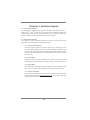
Chapter 1: Introduction
Thank you for purchasing ASRock Z75 Pro3 motherboard, a reliable motherboard
produced under ASRock’s consistently stringent quality control. It delivers excellent
performance with robust design conforming to ASRock’s commitment to quality and
endurance.
In this manual, chapter 1 and 2 contains introduction of the motherboard and step-
by-step guide to the hardware installation. Chapter 3 and 4 contains the confi gura-
tion guide to BIOS setup and information of the Support CD.
Because the motherboard specifi cations and the BIOS software might be
updated, the content of this manual will be subject to change without no-
tice. In case any modifi cations of this manual occur, the updated version
will be available on ASRock website without further notice. You may fi nd
the latest VGA cards and CPU support lists on ASRock website as well.
ASRock website http://www.asrock.com
If you require technical support related to this motherboard, please visit
our website for specifi c information about the model you are using.
www.asrock.com/support/index.asp
1.1 Package Contents
ASRock Z75 Pro3 Motherboard
(ATX Form Factor: 12.0-in x 7.6-in, 30.5 cm x 19.3 cm)
ASRock Z75 Pro3 Quick Installation Guide
ASRock Z75 Pro3 Support CD
2 x Serial ATA (SATA) Data Cables (Optional)
1 x I/O Panel Shield
ASRock Reminds You...
To get better performance in Windows
®
7 / 7 64-bit / Vista
TM
/ Vista
TM
64-
bit, it is recommended to set the BIOS option in Storage Confi guration to
AHCI mode. For the BIOS setup, please refer to the “User Manual” in our
support CD for details.

6
1.2 Specifications
Platform - ATX Form Factor: 12.0-in x 7.6-in, 30.5 cm x 19.3 cm
- All Solid Capacitor design
CPU - Supports 3
rd
and 2
nd
Generation Intel
®
Core
TM
i7 / i5 / i3 in
LGA1155 Package
- Digi Power Design
- 4 + 1 Power Phase Design
- Supports Intel
®
Turbo Boost 2.0 Technology
- Supports Intel
®
K-Series unlocked CPU
- Supports Hyper-Threading Technology (see CAUTION 1)
- Supports Intel
®
Rapid Start Technology and Smart Connect
Technology with Intel
®
Ivy Bridge CPU
Chipset - Intel
®
Z75
Memory - Dual Channel DDR3 Memory Technology (see CAUTION 2)
- 4 x DDR3 DIMM slots
- Supports DDR3 2800+(OC)/2400(OC)/2133(OC)/1866(OC)/
1600/1333/1066 non-ECC, un-buffered memory
- Max. capacity of system memory: 32GB (see CAUTION 3)
- Supports Intel
®
Extreme Memory Profi le (XMP)1.3/1.2
Expansion Slot - 1 x PCI Express 3.0 x16 slot (PCIE2: x16 mode)
(see CAUTION 4)
* PCIE 3.0 is only supported with Intel
®
Ivy Bridge CPU. With
Intel
®
Sandy Bridge CPU, it only supports PCIE 2.0.
- 1 x PCI Express 2.0 x16 slot (PCIE3: x4 mode)
- 1 x PCI Express 2.0 x 1 slot
- 2 x PCI slots
- Supports AMD Quad CrossFireX
TM
and CrossFireX
TM
Graphics * Intel
®
HD Graphics Built-in Visuals and the VGA outputs can
be supported only with processors which are GPU
integrated.
- Supports Intel
®
HD Graphics Built-in Visuals: Intel
®
Quick
Sync Video 2.0, Intel
®
InTru
TM
3D, Intel
®
Clear Video HD
Technology, Intel
®
Insider
TM
, Intel
®
HD Graphics 2500/4000
- Pixel Shader 5.0, DirectX 11 with Intel
®
Ivy Bridge CPU.
Pixel Shader 4.1, DirectX 10.1 with Intel
®
Sandy Bridge CPU
- Max. shared memory 1760MB (see CAUTION 5)
- Dual VGA Output: support HDMI and D-Sub ports by
independent display controllers
- Supports HDMI 1.4a Technology with max. resolution up to
1920x1200 @ 60Hz

7
- Supports D-Sub with max. resolution up to 2048x1536 @
75Hz
- Supports Auto Lip Sync, Deep Color (12bpc), xvYCC and
HBR (High Bit Rate Audio) with HDMI (Compliant HDMI
monitor is required) (see CAUTION 6)
- Supports HDCP function with HDMI port
- Supports Full HD 1080p Blu-ray (BD) / HD-DVD playback
with HDMI port
Audio - 7.1 CH HD Audio with Content Protection
(Realtek ALC892 Audio Codec)
- Premium Blu-ray audio support
- Supports THX TruStudio
TM
LAN - PCIE x1 Gigabit LAN 10/100/1000 Mb/s
- Realtek RTL8111E
- Supports Wake-On-LAN
- Supports LAN Cable Detection
- Supports Energy Effi cient Ethernet 802.3az
- Supports PXE
Rear Panel I/O I/O Panel
- 1 x PS/2 Keyboard Port
- 1 x D-Sub Port
- 1 x HDMI Port
- 4 x Ready-to-Use USB 2.0 Ports
- 2 x Ready-to-Use USB 3.0 Ports
- 1 x RJ-45 LAN Port with LED (ACT/LINK LED and SPEED
LED)
- HD Audio Jack: Side Speaker/Rear Speaker/Central/Bass/
Line in/Front Speaker/Microphone (see CAUTION 7)
SATA3 - 2 x SATA3 6.0 Gb/s connectors, support RAID (RAID 0,
RAID 1, RAID 5, RAID 10 and Intel Rapid Storage), NCQ,
AHCI and Hot Plug functions
USB3.0 - 2 x Rear USB 3.0 ports, support USB 1.0/2.0/3.0 up to
5Gb/s
- 1 x Front USB 3.0 header (supports 2 USB 3.0 ports),
supports USB 1.0/2.0/3.0 up to 5Gb/s
Connector - 4 x SATA2 3.0 Gb/s connectors, support RAID (RAID 0,
RAID 1, RAID 5, RAID 10 and Intel Rapid Storage), NCQ,
AHCI and Hot Plug functions
- 2 x SATA3 6.0Gb/s connectors

8
- 1 x IR header
- 1 x CIR header
- 1 x COM port header
- 1 x HDMI_SPDIF header
- 1 x Power LED header
- CPU/Chassis/Power FAN connector
- 24 pin ATX power connector
- 8 pin 12V power connector
- Front panel audio connector
- 3 x USB 2.0 headers (support 6 USB 2.0 ports)
- 1 x USB 3.0 header (supports 2 USB 3.0 ports)
BIOS Feature - 64Mb AMI UEFI Legal BIOS with GUI support
- Supports “Plug and Play”
- ACPI 1.1 Compliance Wake Up Events
- Supports jumperfree
- SMBIOS 2.3.1 Support
- CPU Core, IGPU, DRAM, 1.8V PLL, VTT, VCCSA Voltage
Multi-adjustment
Support CD - Drivers, Utilities, AntiVirus Software (Trial Version),
CyberLink MediaEspresso 6.5 Trial, ASRock MAGIX
Multimedia Suite - OEM
Unique Feature - ASRock Extreme Tuning Utility (AXTU) (see CAUTION 8)
- ASRock Instant Boot
- ASRock Instant Flash (see CAUTION 9)
- ASRock APP Charger (see CAUTION 10)
- ASRock SmartView (see CAUTION 11)
- ASRock XFast USB (see CAUTION 12)
- ASRock XFast LAN (see CAUTION 13)
- ASRock XFast RAM (see CAUTION 14)
- ASRock Crashless BIOS (see CAUTION 15)
- ASRock OMG (Online Management Guard)
(see CAUTION 16)
- Lucid Virtu Universal MVP (see CAUTION 17)
* Lucid Virtu Universal MVP can be supported only with
processors which are GPU integrated.
- ASRock On/Off Play Technology (see CAUTION 18)
- Hybrid Booster:
- CPU Frequency Stepless Control (see CAUTION 19)
- ASRock U-COP (see CAUTION 20)
- Boot Failure Guard (B.F.G.)
- Combo Cooler Option (C.C.O.) (see CAUTION 21)
- Good Night LED

9
WARNING
Please realize that there is a certain risk involved with overclocking, including
adjusting the setting in the BIOS, applying Untied Overclocking Technology, or using
third-party overclocking tools. Overclocking may affect your system’s stability, or
even cause damage to the components and devices of your system. It should be
done at your own risk and expense. We are not responsible for possible damage
caused by overclocking.
Hardware - CPU Temperature Sensing
Monitor - Chassis Temperature Sensing
- CPU/Chassis/Power Fan Tachometer
- CPU Quiet Fan (Allows Chassis Fan Speed Auto-Adjust by
CPU Temperature)
- CPU/Chassis Fan Multi-Speed Control
- Voltage Monitoring: +12V, +5V, +3.3V, CPU Vcore
OS - Microsoft
®
Windows
®
7 / 7 64-bit / Vista
TM
/ Vista
TM
64-bit /
XP / XP 64-bit compliant (see CAUTION 22)
Certifi cations - FCC, CE, WHQL
- ErP/EuP Ready (ErP/EuP ready power supply is required)
(see CAUTION 23)
* For detailed product information, please visit our website: http://www.asrock.com
CAUTION!
1. About the settings of “Hyper Threading Technology”, please check page
51.
2. This motherboard supports Dual Channel Memory Technology. Before
you implement Dual Channel Memory Technology, make sure to read the
installation guide of memory modules on page 20 for proper installation.
3. Due to the operating system limitation, the actual memory size may be
less than 4GB for the reservation for system usage under Windows
®
7 /
Vista
TM
/ XP. For Windows
®
OS with 64-bit CPU, there is no such limita-
tion. You can use ASRock XFast RAM to utilize the memory that Win-
dows
®
cannot use.
4. Only PCIE2 slot supports Gen 3 speed. To run the PCI Express in Gen
3 speed, please install an Ivy Bridge CPU. If you install a Sandy Bridge
CPU, the PCI Express will run only at PCI Express Gen 2 speed.
5. The maximum shared memory size is defi ned by the chipset vendor and
is subject to change. Please check Intel
®
website for the latest informa-
tion.

10
6. xvYCC and Deep Color are only supported under Windows
®
7 64-bit /
7. Deep Color mode will be enabled only if the display supports 12bpc
in EDID. HBR is supported under Windows
®
7 64-bit / 7 / Vista
TM
64-bit /
Vista
TM
.
7. For microphone input, this motherboard supports both stereo and mono
modes. For audio output, this motherboard supports 2-channel, 4-chan-
nel, 6-channel, and 8-channel modes. Please chec
k the table on page 14
for proper connection.
8. ASRock Extreme Tuning Utility (AXTU) is an all-in-one tool to ne-tune dif-
ferent system functions in a user-friendly interface, which includes Hard-
ware Monitor, Fan Control, Overclocking, OC DNA and IES. In Hardware
Monitor, it shows the major readings of your system. In Fan Control, it
shows the fan speed and temperature for you to adjust. In Overclocking,
you are allowed to overclock CPU frequency for optimal system per-
formance. In OC DNA, you can save your OC settings as a profi le and
share it with your friends. Your friends then can load the OC profi le to
their own system to get the same OC settings. In IES (Intelligent Energy
Saver), the voltage regulator can reduce the number of output phases to
improve effi ciency when the CPU cores are idle without sacrifi cing com-
puting performance. Please visit our website for the operation procedures
of ASRock Extreme Tuning Utility (AXTU).
ASRock website: http://www.asrock.com
9. ASRock Instant Flash is a BIOS fl ash utility embedded in Flash ROM.
This convenient BIOS update tool allows you to update system BIOS
without entering operating systems fi rst like MS-DOS or Windows
®
. With
this utility, you can press the <F6> key during the POST or the <F2>
key to enter into the BIOS setup menu to access ASRock Instant Flash.
Just launch this tool and save the new BIOS fi le to your USB fl ash drive,
fl oppy disk or hard drive, then you can update your BIOS only in a few
clicks without preparing an additional fl oppy diskette or other complicated
fl ash utility. Please be noted that the USB fl ash drive or hard drive must
use FAT32/16/12 fi le system.
10. If you desire a faster, less restricted way of charging your Apple devices,
such as iPhone/iPad/iPod Touch, ASRock has prepared a wonderful so-
lution for you - ASRock APP Charger. Simply install the APP Charger
driver, it makes your iPhone charge much quickly from your computer
and up to 40% faster than before. ASRock APP Charger allows you to
quickly charge many Apple devices simultaneously and even supports
continuous charging when your PC enters into Standby mode (S1), Sus-
pend to RAM (S3), hibernation mode (S4) or power off (S5). With APP
Charger driver installed, you can easily enjoy the marvelous charging
experience.
ASRock website: http://www.asrock.com/Feature/AppCharger/index.asp

11
11. ASRock SmartView, a new function for internet browsers, is the smart
start page for IE that combines your most visited web sites, your history,
your Facebook friends and your real-time newsfeed into an enhanced
view for a more personal Internet experience. ASRock motherboards are
exclusively equipped with the ASRock SmartView utility that helps you
keep in touch with friends on-the-go. To use ASRock SmartView feature,
please make sure your OS version is Windows
®
7 / 7 64 bit / Vista
TM
/
Vista
TM
64 bit, and your browser version is IE8.
ASRock website: http://www.asrock.com/Feature/SmartView/index.asp
12. ASRock XFast USB can boost USB storage device performance. The
performance may depend on the properties of the device.
13. ASRock XFast LAN provides a faster internet access, which includes
the benefi ts listed below. LAN Application Prioritization: You can confi g-
ure your application’s priority ideally and/or add new programs. Lower
Latency in Game: After setting online game’s priority higher, it can lower
the latency in games. Traffi c Shaping: You can watch Youtube HD videos
and download simultaneously. Real-Time Analysis of Your Data: With
the status window, you can easily recognize which data streams you are
transferring currently.
14. ASRock XFast RAM is a new function that is included into ASRock Ex-
treme Tuning Utility (AXTU). It fully utilizes the memory space that cannot
be used under Windows
®
OS 32-bit CPU. ASRock XFast RAM shortens
the loading time of previously visited websites, making web surfi ng faster
than ever. And it also boosts the speed of Adobe Photoshop 5 times
faster. Another advantage of ASRock XFast RAM is that it reduces the
frequency of accessing your SSDs or HDDs in order to extend their lifes-
pan.
15. ASRock Crashless BIOS allows users to update their BIOS without fear
of failing. If power loss occurs during the BIOS update process, ASRock
Crashless BIOS will automatically fi nish the BIOS update procedure after
regaining power. Please note that BIOS fi les need to be placed in the root
directory of your USB disk. Only USB2.0 ports support this feature.
16. Administrators are able to establish an internet curfew or restrict internet
access at specifi ed times via OMG. You may choose from [Everyday], [Day
of the week] or [Weekdays and weekends], then schedule the starting
and ending hours of internet access granted to other users. In order to
prevent users from bypassing OMG, guest accounts without permission
to modify the system time are required.
17. VIRTU Universal MVP includes the base features of Virtu Universal
technology, which virtualizes integrated GPU and discrete GPU for best
of breed functionality. It also features Virtual Vsync™ for no-compromise
visual quality. With the added benefits of HyperFormance technology,
VIRTU Universal MVP improves game performance by intelligently reduc-
ing redundant rendering tasks in the fl ow between the CPU, GPU and the
display.

12
18. ASRock On/Off Play Technology allows users to enjoy the great audio
experience from portable audio devices, such as MP3 players or mobile
phones to your PC, even when the PC is turned off (or in ACPI S5 mode)!
This motherboard also provides a free 3.5mm audio cable (optional) that
ensures users the most convenient computing environment.
19. Although this motherboard offers stepless control, it is not recommended
to perform over-clocking. Frequencies other than the recommended CPU
bus frequencies may cause instability of the system or damage the CPU.
20. While CPU overheat is detected, the system will automatically shutdown.
Before you resume the system, please check if the CPU fan on the moth-
erboard functions properly and unplug the power cord, then plug it back
again. To improve heat dissipation, remember to spray thermal grease
between the CPU and the heatsink when you install the PC system.
21. Combo Cooler Option (C.C.O.) provides the fl exible option to adopt three
different CPU cooler types, Socket LGA 775, LGA 1155 and LGA 1156.
Please be noticed that not all the 775 and 1156 CPU Fan can be used.
22. ASRock XFast RAM is not supported by Microsoft
®
Windows
®
XP / XP
64-bit. Intel
®
Smart Connect Technology and Intel
®
USB 3.0 ports are not
supported by Microsoft
®
Windows
®
Vista
TM
/ Vista
TM
64-bit / XP / XP 64-
bit.
23. EuP stands for Energy Using Product, w
as a provision regulated by the
European Union to define the power consumption for the completed
system. According to EuP, the total AC power of the completed system
should be under 1.00W in off mode condition. To meet EuP standards,
an EuP ready motherboard and an EuP ready power supply are required.
According to Intel’s suggestion, the EuP ready power supply must meet
the standard of 5v, and the standby power effi ciency should be higher
than 50% under 100 mA current consumption. For EuP ready power sup-
ply selection, we recommend you to check with the power supply manu-
facturer for more details.

13
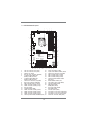
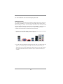
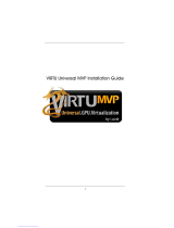
1.3 Motherboard Layout
1 CPU Fan Connector (CPU_FAN1)
2 CPU Fan Connector (CPU_FAN2)
3 1155-Pin CPU Socket
4 ATX 12V Power Connector (ATX12V1)
5 2 x 240-pin DDR3 DIMM Slots
(DDR3_A1, DDR3_B1, Black)
6 2 x 240-pin DDR3 DIMM Slots
(DDR3_A2, DDR3_B2, Black)
7 Chassis Fan Connector (CHA_FAN1)
8 ATX Power Connector (ATXPWR1)
9 USB 3.0 Header (USB3_0_1, Black)
10 SATA3 Connectors (SATA3_1, Gray)
11 SATA3 Connectors (SATA3_0, Gray)
12 Intel Z75 Chipset
13 SPI Flash Memory (64Mb)
14 SATA2 Connectors (SATA2_2, Black)
15 SATA2 Connectors (SATA2_3, Black)
16 SATA2 Connectors (SATA2_4, Black)
17 SATA2 Connectors (SATA2_5, Black)
18 Chassis Speaker Header (SPEAKER1, Black)
19 Power LED Header (PLED1)
20 System Panel Header (PANEL1, Black)
21 Chassis Fan Connector (CHA_FAN2)
22 USB 2.0 Header (USB4_5, Black)
23 USB 2.0 Header (USB6_7, Black)
24 USB 2.0 Header (USB8_9, Black)
25 Consumer Infrared Module Header
(CIR1, Gray)
26 Infrared Module Header (IR1)
27 Clear CMOS Jumper (CLRCMOS1)
28 COM Port Header (COM1)
29 HDMI_SPDIF Header
(HDMI_SPDIF1, Black)
30 Front Panel Audio Header
(HD_AUDIO1, Black)
31 PCI Slots (PCI1-2, Black)
32 PCI Express 2.0 x16 Slot (PCIE3, Black)
33 PCI Express 3.0 x16 Slot (PCIE2, Black)
34 PCI Express 2.0 x1 Slot (PCIE1, Black)
35 Power Fan Connector (PWR_FAN1)
Intel
Z75
SATA2_2
SATA2_3
CHA_FAN2
64Mb
BIOS
DDR3_A2 (64 bit, 240-pin module)
DDR3_A1 (64 bit, 240-pin module)
DDR3_B2 (64 bit, 240-pin module)
DDR3_B1 (64 bit, 240-pin module)
ATX12V1
CPU_FAN1
CMOS
Battery
Super
I/O
USB 2.0
T: U SB 0
B: USB1
PS2
Keyboard
ATXPWR1
1
USB3_0_1
CPU_FAN2
AUDIO
CODEC
LAN
PHY
1
HD_AUDIO1
1
HDMI_SPDIF1
COM1
1
CLRCMOS1
1
IR1
1
USB8_9
1
CIR1
1
USB6_7
1
HDLED RESET
PLED PWRBTN
PANEL1
1
PLED1
1
1
SPEAKER1
PCIE1
PCIE2
PCIE3
PCI1
CHA_FAN1
PWR_FAN1
VGA1
HDMI1
USB 3.0
T:USB2
B: USB3
Top:
RJ-45
USB 2.0
T: USB2
B: USB3
19.3cm (7.6 in)
30.5cm (12.0 in)
1
2
3
4
5
6
7
8
9
10
11
12
13
14
18
19
15
16
17
20
21
22
23
24
25
26
27
28
29
30
31
32
33
34
35
DDR3 2800+
RoHS
Front USB 3.0
Z75 Pro3
XFast USB
XFast LAN
PCI Express 3.0
ErP/EuP Ready
X ast RAMF
PCI2
SATA2_4
SATA2_5
SATA3_1
SATA3_0
Top:
SIDE SPK
Center:
REAR SPK
Bottom:
CTR BASS
Top:
LINE IN
Center:
FRONT
Bottom:
MIC IN
USB4_5
1

14
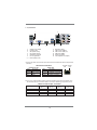
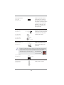
1.4 I/O Panel
* There are two LED next to the LAN port. Please refer to the table below for the LAN port LED
indications.
LAN Port LED Indications
Activity/Link LED SPEED LED
Status Description Status Description
Off No Link Off 10Mbps connection
Blinking Data Activity Orange 100Mbps connection
On Link Green 1Gbps connection
1 USB 2.0 Ports (USB01) 8 Microphone (Pink)
* 2 LAN RJ-45 Port 9 USB 2.0 Ports (USB23)
3 Side Speaker (Gray) 10 USB 3.0 Ports (USB3_23)
4 Rear Speaker (Black) 11 HDMI Port (HDMI1)
5 Central / Bass (Orange) 12 D-Sub Port (VGA1)
6 Line In (Light Blue) 13 PS/2 Keyboard Port (Purple)
** 7 Front Speaker (Lime)
ACT/LINK
LED
SPEED
LED
LAN Port
**
If you use 2-channel speaker, please connect the speaker’s plug into “Front Speaker Jack”.
See the table below for connection details in accordance with the type of speaker you use.
TABLE for Audio Output Connection
Audio Output Channels Front Speaker Rear Speaker Central / Bass Line in
(No. 7) (No. 4) (No. 5) (No. 6)
2 V -- -- --
4 V V -- --
6 V V V --
8 V V V V
1
2
910
11
12
13
6
7
8
4
3
5

15
To enable Multi-Streaming function, you need to connect a front panel audio cable to the front
panel audio header. After restarting your computer, you will fi nd “Mixer” tool on your system.
Please select “Mixer ToolBox” , click “Enable playback multi-streaming”, and click
“ok”. Choose “2CH”, “4CH”, “6CH”, or “8CH” and then you are allowed to select “Realtek HDA
Primary output” to use Rear Speaker, Central/Bass, and Front Speaker, or select “Realtek
HDA Audio 2nd output” to use front panel audio.

16
Chapter 2: Installation
This is an ATX form factor (12.0" x 7.6", 30.5 x 19.3 cm) motherboard. Before you
install the motherboard, study the confi guration of your chassis to ensure that the
motherboard fi ts into it.
Make sure to unplug the power cord before installing or removing the
motherboard. Failure to do so may cause physical injuries to you and
damages to motherboard components.
2.1 Screw Holes
Place screws into the holes indicated by circles to secure the motherboard to the
chassis.
Do not over-tighten the screws! Doing so may damage the motherboard.
2.2 Pre-installation Precautions
Take note of the following precautions before you install motherboard components
or change any motherboard settings.
1. Unplug the power cord from the wall socket before touching any
components.
2. To avoid damaging the motherboard’s components due to static
electricity, NEVER place your motherboard directly on the carpet
or the like. Also remember to use a grounded wrist strap or touch a
safety grounded object before you handle the components.
3. Hold components by the edges and do not touch the ICs.
4. Whenever you uninstall any component, place it on a grounded anti-
static pad or in the bag that comes with the component.
5. When placing screws into the screw holes to secure the mother-
board to the chassis, please do not over-tighten the screws! Doing
so may damage the motherboard.
Before you install or remove any component, ensure that the power is
switched off or the power cord is detached from the power supply. Failure to do
so may cause severe damage to the motherboard, peripherals, and/or
components.

17
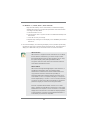
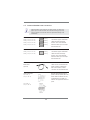
2.3 CPU Installation
For the installation of Intel 1155-Pin CPU,
please follow the steps below.
Before you insert the 1155-Pin CPU into the socket, please check if the
CPU surface is unclean or if there are any bent pins in the socket. Do
not force to insert the CPU into the socket if above situation is found.
Otherwise, the CPU will be seriously damaged.
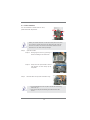
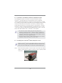
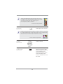
Step 1. Open the socket:
Step 1-1. Disengage the lever by pressing it
down and sliding it out of the hook.
Step 1-2. Keep the lever positioned at about
135 degrees in order to flip up the
load plate.
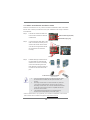
Step 2. Remove the PnP Cap (Pick and Place Cap).
1. It is recommended to use the cap tab to handle and avoid kicking
off the PnP cap.
2. This cap must be placed if returning the motherboard for after
service.
1155-Pin Socket Overview
Contact Array
Socket Body
Load Lever
Load Plate

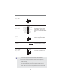
18
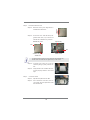
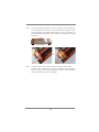
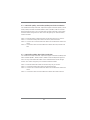
Pin1
alignment key
alignment key
Pin1
1155-Pin CPU
Step 3. Insert the 1155-Pin CPU:
Step 3-1. Hold the CPU by the edge which is
marked with a black line.
Step 3-2. Orient the CPU with the IHS (Inte-
grated Heat Sink) up. Locate Pin1
and the two orientation key notches.
For proper inserting, please ensure to match the two orientation key
notches of the CPU with the two alignment keys of the socket.
Step 3-3. Carefully place the CPU into the
socket by using a purely vertical mo-
tion.
Step 3-4. Verify that the CPU is within the sock-
et and properly mated to the orient
keys.
Step 4. Close the socket:
Step 4-1. Flip the load plate onto the IHS.
Step 4-2. Press down the load lever, and se-
cure it with the load plate tab under
the retention tab.
black line
orientation key notch
orientation key notch 1155-Pin Socket

19
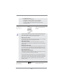
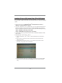
2.4 Installation of CPU Fan and Heatsink
This motherboard is equipped with 1155-Pin socket that supports Intel 1155-Pin
CPUs. Please adopt the type of heatsink and cooling fan compliant with Intel 1155-
Pin CPU to dissipate heat. Before you install the heatsink, you need to spray ther-
mal interface material between the CPU and the heatsink to improve heat dissipa-
tion. Ensure that the CPU and the heatsink are securely fastened and in good con-
tact with each other. Then connect the CPU fan to the CPU_FAN connector (CPU_
FAN1, see page 13, No. 1 or CPU_FAN2, see page 13. No.2).
For proper installation, please kindly refer to the instruction manuals of your
CPU fan and heatsink.
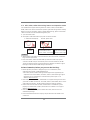
Below is an example to illustrate the installation of the heatsink for 1155-Pin CPUs.
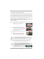
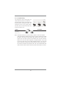
Step 1. Apply thermal interface material onto the cen-
ter of the IHS on the socket’s surface.
Step 2. Place the heatsink onto the socket. Ensure
that the fan cables are oriented on side closest
to the CPU fan connector on the motherboard
(CPU_FAN1, see page 13, No. 1 or CPU_
FAN2, see page 13. No.2).
Step 3. Align fasteners with the motherboard through-
holes.
Step 4. Rotate the fastener clockwise, then press
down on fastener caps with thumb to install
and lock. Repeat with remaining fasteners.
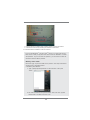
If you press down the fasteners without rotating them clockwise, the
heatsink cannot be secured on the motherboard.
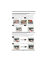
Step 5. Connect fan header with the CPU fan connector on the motherboard.
Step 6. Secure redundant cable with tie-wrap to ensure the cable does not
interfere with fan operation or contact other components.
Apply Thermal
Interface Material
Fan cables on side
closest to MB header
Fastener slots
pointing straight out
Press Down
(4 Places)
Please be noticed that this motherboard supports Combo Cooler
Option (C.C.O.), which provides fl exible options to adopt three dif-
ferent CPU cooler types, Socket LGA 775, LGA 1155 and LGA 1156.
The white throughholes are for Socket LGA
1155/1156 CPU fan.

20
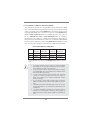
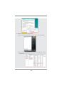
2.5 Installation of Memory Modules (DIMM)
This motherboard provides four 240-pin DDR3 (Double Data Rate 3) DIMM
slots, and supports Dual Channel Memory Technology. For dual channel confi g-
uration, you always need to install identical (the same brand, speed, size and
chip-type) DDR3 DIMM pair in the slots: You have to install identical DDR3
DIMMs in Dual Channel A (DDR3_A1 and DDR3_B1; Black slots; see p.13
No. 5) or identical DDR3 DIMMs in Dual Channel B (DDR3_A2 and DDR3_
B2; Black slots; see p.13 No. 6), so that Dual Channel Memory Technology can
be activated. This motherboard also allows you to install four DDR3 DIMMs
for dual channel confi guration, please install identical DDR3 DIMMs in all four
slots. You may refer to the Dual Channel Memory Confi guration Table below.
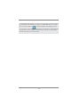
Dual Channel Memory Confi guration
DDR3_A1 DDR3_A2 DDR3_B1 DDR3_B2
(Black Slot) (Black Slot) (Black Slot) (Black Slot)
(1) Populated - Populated -
(2) - Populated - Populated
(3)* Populated Populated Populated Populated
* For confi guration (3), please install identical DDR3 DIMMs in all four
slots.
1. If you want to install two memory modules, for optimal compatibility
and reliability, it is recommended to install them in the slots: DDR3_
A1 and DDR3_B1, or DDR3_A2 and DDR3_B2.
2. If only one memory module or three memory modules are installed
in the DDR3 DIMM slots on this motherboard, it is unable to activate
Dual Channel Memory Technology.
3. If a pair of memory modules is NOT installed in the same Dual
Channel, for example, installing a pair of memory modules in
DDR3_A1 and DDR3_A2, it is unable to activate Dual Channel
Memory Technology.
4. It is not allowed to install a DDR or DDR2 memory module into
DDR3 slot; otherwise, this motherboard and DIMM may be dam-
aged.
5. Some DDR3 1GB double-sided DIMMs with 16 chips may not work
on this motherboard. It is not recommended to install them on this
motherboard.
6. For optimal compatibility and stability while overclocking memory
frequency, it is recommended to install one memory module in
DDR3_B2 slot or two memory modules in DDR3_A2 and DDR3_B2
slots.
Page is loading ...
Page is loading ...
Page is loading ...
Page is loading ...
Page is loading ...
Page is loading ...
Page is loading ...
Page is loading ...
Page is loading ...
Page is loading ...
Page is loading ...
Page is loading ...
Page is loading ...
Page is loading ...
Page is loading ...
Page is loading ...
Page is loading ...
Page is loading ...
Page is loading ...
Page is loading ...
Page is loading ...
Page is loading ...
Page is loading ...
Page is loading ...
Page is loading ...
Page is loading ...
Page is loading ...
Page is loading ...
Page is loading ...
Page is loading ...
Page is loading ...
Page is loading ...
Page is loading ...
Page is loading ...
Page is loading ...
Page is loading ...
Page is loading ...
Page is loading ...
Page is loading ...
Page is loading ...
Page is loading ...
Page is loading ...
Page is loading ...
Page is loading ...
Page is loading ...
Page is loading ...
Page is loading ...
Page is loading ...
Page is loading ...
Page is loading ...
-
 1
1
-
 2
2
-
 3
3
-
 4
4
-
 5
5
-
 6
6
-
 7
7
-
 8
8
-
 9
9
-
 10
10
-
 11
11
-
 12
12
-
 13
13
-
 14
14
-
 15
15
-
 16
16
-
 17
17
-
 18
18
-
 19
19
-
 20
20
-
 21
21
-
 22
22
-
 23
23
-
 24
24
-
 25
25
-
 26
26
-
 27
27
-
 28
28
-
 29
29
-
 30
30
-
 31
31
-
 32
32
-
 33
33
-
 34
34
-
 35
35
-
 36
36
-
 37
37
-
 38
38
-
 39
39
-
 40
40
-
 41
41
-
 42
42
-
 43
43
-
 44
44
-
 45
45
-
 46
46
-
 47
47
-
 48
48
-
 49
49
-
 50
50
-
 51
51
-
 52
52
-
 53
53
-
 54
54
-
 55
55
-
 56
56
-
 57
57
-
 58
58
-
 59
59
-
 60
60
-
 61
61
-
 62
62
-
 63
63
-
 64
64
-
 65
65
-
 66
66
-
 67
67
-
 68
68
-
 69
69
-
 70
70


Ask a question and I''ll find the answer in the document
Finding information in a document is now easier with AI
Related papers
-
ASROCK ZH77 Pro3 User manual
-
ASROCK B85iCafe4 Owner's manual
-
ASROCK A55iCafe User manual
-
ASROCK Z87iCafe4 Quick start guide
-
-
ASROCK P65iCafe Owner's manual
-
ASROCK P75 Pro3 User manual
-
ASROCK H77WS-DL Owner's manual
-
-
Other documents
-
 Cables Direct USB3-PCI2P Datasheet
-
Biostar B75MU3+ 6.x User manual
-
 MeLe STAR CLOUD PCG03 PLUS Quick start guide
-
SIIG LB-US0014-S1 Installation guide
-
Digitus DA-70300-1 Datasheet
-
 Lucid Virtu MVP Installation guide
-
Intel BOXDZ75M45K Datasheet
-
ECS Z77H2-A2X DELUXE (V1.0) User manual
-
Biostar TZ68K+ Owner's manual
-
Biostar TZ68A User manual


