Frigidaire FGEW3066UFB Installation guide
- Category
- Ovens
- Type
- Installation guide

1
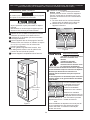
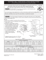
ELECTRIC WALL OVEN INSTALLATION INSTRUCTIONS
(with side-by-side and cooktop combination specialty installations)
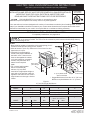
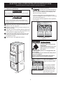
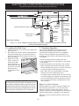
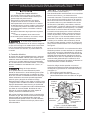
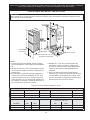
Figure 1
27" and 30" Single Wall Ovens
PN 807153706 Rev. B (2019/10)
English – pages 1-10
Español – páginas 11-20
Français – pages 21-30
All dimensions are in inches (cm).
Do not remove spacers (if equipped) on the side walls of the built-in oven. These spacers
center the oven in the space provided. The oven must be centered to prevent excess heat buildup that may
UHVXOWLQKHDWGDPDJHRU¿UH
NOTES:
1. Base must be capable of supporting 150 pounds (68 kg) for 27"
models and 200 pounds (90 kg) for 30" models.
2. Allow at least 21" (53.3 cm) clearance in front of oven for door
depth when it is open.
than the maximum (H),
add one 2"(5 cm) wide
3. Dimension G (cutout depth) is
critical to the proper installation of
the built-in oven. If the oven trim
does not butt against the cabinet,
or if noise is heard on convection
models, verify dimension G to
assure it is the required
depth.
4. For a cutout height greater
Printed in U.S.A.
6XJJHVWHGGLVWDQFHIURPÀRRULVFP
Minimum required distance is 4 ½" (11.4cm).
INSTALLATION AND SERVICE MUST BE PERFORMED BY A QUALIFIED INSTALLER.
IMPORTANT: SAVE FOR LOCAL ELECTRICAL INSPECTOR'S USE.
READ AND SAVE THESE INSTRUCTIONS FOR FUTURE REFERENCE.
FOR YOUR SAFETY: Do not store or use gasoline or other
ÀDPPDEOHYDSRUVDQGOLTXLGVLQWKHYLFLQLW\RIWKLVRUDQ\RWKHUDSSOLDQFH
<RXUQHZZDOORYHQKDVEHHQGHVLJQHGWR¿WDYDULHW\RIFXWRXWVL]HVWRPDNHWKHMRERILQVWDOOLQJHDVLHU7KH¿UVW
step of your installation should be to measure your current cutout dimensions and compare them to the cutout
GLPHQVLRQVFKDUWEHORZIRU\RXUPRGHO<RXPD\¿QGOLWWOHRUQRFDELQHWZRUNEHLQJQHFHVVDU\
PRODUCT DIMENSIONS
MODEL A B C D
27" (68.6 cm) 27 (68.6) 29
1
/
2
(74.9) 24
5
/
8
(62.5) 24
3
/
4
(62.9)
30" (76.2 cm) 30 (76.2) 29 (73.7) 28
1
/
4
(71.8) 24
3
/
4
(62.9)
CUTOUT DIMENSIONS AND CABINET WIDTH
FG
H. Standard Height
(**Others, see notes 4 & 5)
I
MODEL Min. Max. Min. Min. Max.
27" (68.6 cm) 24
7
/
8
(63.2) 25¼ (64.1) 24 (61.0) 27¼ (69.2) 28
1
/
4
(71.8) 27
1
/
8
(68.9) Min
30" (76.2 cm) 28
1
/
2
(72.4) 29 (73.7) 24 (61.0) 27¼ (69.2) 28
1
/
8
(71.4) 30
1
/
8
(76.5) Min
United States
and Canada
wood shim of appropriate height to
each side of the opening under the
appliance side rails.You can order a
larger bottom trim through a Service
Center.
Hole for
Cord
Electrical
Junction Box
2" (5 cm) Wide Wood
Spacer if Needed
B
A
D
C
H
F
I
G
27 1/4”
(69.2 cm)
2”
(5.1 cm)
Min.
31”*
(78.7 cm)
3”
(7.6 cm)
1½” (3.8 cm)
Min.
Door Open
(see note 2)
Spacer
SINGLE WALL OVEN - SINGLE INSTALLATION
For specialty installations, see pages 8-10

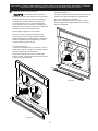
2
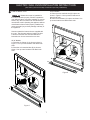
ELECTRIC WALL OVEN INSTALLATION INSTRUCTIONS
(with side-by-side and cooktop combination specialty installations)
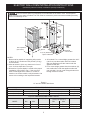
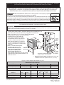
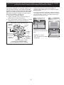
Figure 2
27" and 30" Double Wall Ovens
Do not remove spacers (if equipped) on the side walls of the built-in oven. These spacers
center the oven in the space provided. The oven must be centered to prevent excess heat buildup that may
UHVXOWLQKHDWGDPDJHRU¿UH
NOTES:
1. Base must be capable of supporting 300 pounds
(136 kg) for 27" models and 375 pounds (170 kg)
for 30" models.
2. Allow at least 21" (53.3 cm) clearance in front of
oven for door depth when it is open.
3. Dimension G (cutout depth) is critical to the proper
installation of the built-in oven. If the oven trim
does not butt against the cabinet, or if noise is
heard on convection models, verify dimension G to
assure it is according to the required dimension.
4. 30" models: For a cutout height greater than 49
3
/
4
"
(126.5 cm) use the wooden shim kit included
ZLWK\RXUDSSOLDQFHWR¿WWKHFXWRXWXQGHUWKH
appliance side rails.
5. For a cutout height greater than the maximum (H),
use a taller shim under the appliance side rails
(not included). You can order a larger bottom trim
through a Service Center.
All dimensions are in inches (cm).
B
A
D
F
I
H
G
C
48 5/8”
(123.5 cm)
11½”
(29.2 cm)
2”
(5.1 cm)
Min.
3” (7.6 cm)
Max.
1½” (3.8 cm)
Min.
Door Open
(see note 2)
Hole for
Cable
Electrical
Junction Box
2" (5 cm) Wide Wood
Spacer if Needed
Spacer
PRODUCT DIMENSIONS
MODEL A B C D
27" (68.6 cm) 27 (68.6) 50
7
/
8
(129.2) 24
5
/
8
(62.5) 24
3
/
4
(62.9)
30" (76.2 cm) 30 (76.2) 50
3
/
4
(128.9) 28
1
/
4
(71.8) 24
3
/
4
(62.9)
CUTOUT DIMENSIONS AND CABINET WIDTH
F G (Min.)
H. Standard Height
(**Others, see notes 4 & 5)
I
MODEL Min. Max. Min. Max.
27" (68.6 cm) 24
7
/
8
(63.2) 25
1
/
4
(64.1) 24 (61.0) 48
7
/
8
(124.1) 49
7
/
8
(126.7) 27
1
/
8
(68.9) Min
30" (76.2 cm) 28
1
/
2
(72.4) 29 (73.7) 24 (61.0) 48
7
/
8
(124.1) 50
1
/
4
(127.6) 30
1
/
8
(76.5) Min

3
ELECTRIC WALL OVEN INSTALLATION INSTRUCTIONS
(with side-by-side and cooktop combination specialty installations)
Important Notes to the Installer
1. Read all instructions contained in these installation
instructions before installing the wall oven.
2. Remove all packing material from the oven
compartments before connecting the electrical
supply to the wall oven.
3. Observe all governing codes and ordinances.
4. Be sure to leave these instructions with the
consumer.
5. Remove oven door to facilitate installation. See Use
and Care guide for instructions.
6. THESE OVENS ARE NOT APPROVED FOR
STACKABLE OR SIDE-BY-SIDE INSTALLATION.
Important Note to the Consumer
Keep these instructions with your Owner's Guide for the
local electrical inspector's use and future reference.
IMPORTANT SAFETY
INSTRUCTIONS
• Be sure your wall oven is installed and grounded
SURSHUO\E\DTXDOL¿HGLQVWDOOHURUVHUYLFHWHFKQLFLDQ
• This wall oven must be electrically grounded in
accordance with local codes or, in their absence,
with the National Electrical Code ANSI/NFPA No.70-
latest edition in United Sates, or with CSA Standard
C22.1, Canadian Electrical Code, Part 1, in Canada.
Stepping, leaning or sitting on the door
RIWKLVZDOORYHQFDQUHVXOWLQVHULRXVLQMXULHVDQGFDQ
also cause damage to the wall oven.
• Never use your wall oven for warming or heating
the room. Prolonged use of the wall oven without
adequate ventilation can be dangerous.
The electrical power to the oven must be
VKXWRႇZKLOHOLQHFRQQHFWLRQVDUHEHLQJPDGH)DLOXUHWR
GRVRFRXOGUHVXOWLQVHULRXVLQMXU\RUGHDWK
1. Carpentry
5HIHUWR¿JXUHRUIRUWKHGLPHQVLRQVDSSOLFDEOHWR
your appliance, and the space necessary to receive the
oven. The oven support surface may be solid plywood
or similar material, however the surface must be level
from side to side and from front to rear.
$GMXVWLQJ2YHQ+HLJKW
2YHQKHLJKWFDQEHDGMXVWHGZLWKFPZLGHZRRG
VKLPVZKHQQHHGHGWR¿WLQWRDQH[LVWLQJFDELQHW
cutout opening, when cutout height exceeds 28
1
/
4
"
(71.8 cm)
for the single wall oven or 49
5
/
8
" (126cm) for
the double wall oven (see Figure 1 or 2). Place shims
of appropriate height beneath the oven side rails.
3. Electrical Requirements
Each appliance must be supplied with the proper
voltage and frequency, and connected to an individual,
properly grounded branch circuit, protected by a circuit
breaker or fuse. To know the circuit breaker or fuse
UHTXLUHGE\\RXUPRGHOVHHWKHVHULDOSODWHWR¿QGWKH
wattage consumption and refer to table A to get the
circuit breaker or fuse amperage.
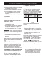
Table A
Observe all governing codes and local ordinances
1. A 3-wire or 4-wire single phase 120/240 or 120/208
9ROW+]$&RQO\HOHFWULFDOVXSSO\LVUHTXLUHGRQ
a separate circuit fused on both sides of the line
(red and black wires). A time-delay fuse or circuit
breaker is recommended. DO NOT fuse neutral
(white wire). Only certain cooktop models may be
installed over certain built-in electric oven models.
Approved cooktops and built-in ovens are listed by
the MFG ID number (see the insert sheet included in
the literature package). Do not install a cooktop over
a side-by-side wall oven installation.
127(:LUHVL]HVDQGFRQQHFWLRQVPXVWFRQIRUPZLWK
WKHIXVHVL]HDQGUDWLQJRIWKHDSSOLDQFHLQDFFRUGDQFH
with the American National Electrical Code ANSI/NFPA
No. 70-latest edition, or with Canadian CSA Standard
C22.1, Canadian Electrical Code, Part 1, and local
codes and ordinances.
An extension cord should not be used
ZLWKWKLVDSSOLDQFH6XFKXVHPD\UHVXOWLQD¿UH
HOHFWULFDOVKRFNRURWKHUSHUVRQDOLQMXU\,I\RXQHHGD
longer power cord you can purchase a 10' (3 m) power
cord kit #903056-9010 by calling the Service Center.
2. These appliances should be connected to the
fused disconnect (or circuit breaker) box through
ÀH[LEOHDUPRUHGRUQRQPHWDOOLFVKHDWKHGFDEOH
7KHÀH[LEOHDUPRUHGFDEOHH[WHQGLQJIURPWKH
appliance should be connected directly to the
MXQFWLRQER[7KHMXQFWLRQER[VKRXOGEHORFDWHG
as shown in Figure 1 or Figure 2 and with as much
slack as possible remaining in the cable between
the box and the appliance, so it can be moved if
servicing is ever necessary.
3. A suitable strain relief must be provided to attach
WKHÀH[LEOHDUPRUHGFDEOHWRWKHMXQFWLRQER[
Appliance
Rating Watts
240V
Protection
Circuit
Recommended
Appliance
Rating Watts
208V
Protection
Circuit
Recommended
Less than
4800W
20A
Less than
4100W
20A
4801W - 7200W
30A
4101W - 6200W
30A
7201W - 9600W
40A or 50A
6201W - 8300W
40A or 50A
9601W and +
50A
8301W and +
50A

4
ELECTRIC WALL OVEN INSTALLATION INSTRUCTIONS
(with side-by-side and cooktop combination specialty installations)
In cold weather shipping and storage
FRQGLWLRQVPDNHVXUHWKDWRYHQLVLQ¿QDOORFDWLRQ
at least three (3) hours before switching on power.
Switching on power while oven is still cold may
damage the oven controls.
4. Electrical connection
It is the responsibility and obligation of the consumer to
FRQWDFWDTXDOL¿HGLQVWDOOHUWRDVVXUHWKDWWKHHOHFWULFDO
installation is adequate and is in conformance
with the National Electrical Code ANSI/NFPA No.
70-latest edition, or with CSA Standard C22.1,
Canadian Electrical Code, Part 1, and local codes and
ordinances.
Risk of electrical shock (Failure to
heed this warning may result in electrocution or
RWKHUVHULRXVLQMXU\7KLVDSSOLDQFHLVHTXLSSHGZLWK
copper lead wire. If connection is made to aluminum
house wiring, use only connectors that are approved
IRUMRLQLQJFRSSHUDQGDOXPLQXPZLUHLQDFFRUGDQFH
with the National Electrical Code and local code and
ordinances. When installing connectors having screws
which bear directly on the steel and/or aluminum
ÀH[LEOHFRQGXLWGRQRWLJKWHQVFUHZVVXႈFLHQWO\WR
GDPDJHWKHÀH[LEOHFRQGXLW'RQRWRYHUEHQGRU
H[FHVVLYHO\GLVWRUWÀH[LEOHFRQGXLWWRDYRLGVHSDUDWLRQ
of convolutions en exposure of internal wires.
DO NOT ground to a gas supply pipe. DO NOT
connect to electrical power supply until appliance
is permanently grounded. Connect the ground wire
before turning on the power.
(If your appliance is equipped with a
white neutral conductor.)
This appliance is manufactured with a white neutral
power supply and a frame connected copper wire. The
frame is grounded by connection of grounding lead to
neutral lead at the termination of the conduit, if used in
USA, in a new branch circuit installation (1996 NEC),
mobile home, recreational vehicles, where local code
do not permit grounding trough the neutral (white) wire
or in Canada, disconnect the white and green lead
from each other and use ground lead to ground unit in
accordance with local codes, connect neutral lead to
branch circuit-neutral conductor in usual manner see
Figure 4. If your appliance is to be connected to a 3
ZLUHJURXQGHGMXQFWLRQER[86RQO\ZKHUHORFDOFRGH
permit connecting the appliance-grounding conductor
to the neutral (white) see Figure 3.
NOTE TO ELECTRICIAN: The armored cable leads
VXSSOLHGZLWKWKHDSSOLDQFHDUH8/UHFRJQL]HGIRU
connection to larger gauge household wiring. The
insulation of the leads is rated at temperatures much
higher than temperature rating of household wiring.
The current carrying capacity of the conductor is
governed by the temperature rating of the insulation
around the wire, rather than the wire gauge alone.
Where local codes permit connecting the appliance-
grounding conductor to the neutral (white) wire (US
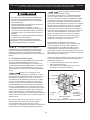
2QO\VHH¿JXUH
1. Disconnect the power supply.
,QWKHMXQFWLRQER[
connect appliance and power supply cable wires as
shown in Figure 3.
(OHFWULFDO6KRFN+D]DUG
• Electrical ground is required on this appliance.
• Do not connect to the electrical supply until
appliance is permanently grounded.
'LVFRQQHFWSRZHUWRWKHMXQFWLRQER[EHIRUH
making the electrical connection.
• This appliance must be connected to a grounded,
metallic, permanent wiring system, or a grounding
connector should be connected to the grounding
terminal or wire lead on the appliance.
• Do not use a gas supply line for grounding the
appliance.
)DLOXUHWRGRDQ\RIWKHDERYHFRXOGUHVXOWLQD¿UH
SHUVRQDOLQMXU\RUHOHFWULFDOVKRFN
Figure 3
3-WIRE GROUNDED JUNCTION BOX
Cable from Power Supply
Black
Wires
Junction
Box
Cable from appliance
Ground Wire
(Bare or Green Wire)
White Wire
(Neutral)
U.L.-Listed Conduit
Connector (or CSA listed)
Red
Wires
White Wire
(Neutral)

5
ELECTRIC WALL OVEN INSTALLATION INSTRUCTIONS
(with side-by-side and cooktop combination specialty installations)
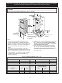
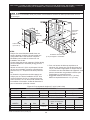
Model and Serial Number Location
The serial plate is located along the interior side trim of
the oven and visible when the door is opened.
When ordering parts for or making inquires about your
oven, always be sure to include the model and serial
numbers and a lot number or letter from the serial plate
on your oven.
Single Wall Oven
Serial Plate Location
Double Wall Oven
Serial Plate Location
If oven is used in a new branch circuit installation
(1996 NEC), mobile home, recreational vehicle, or
where local codes DO NOT permit grounding through
the neutral (white) wire, the appliance frame MUST
NOT be connected to the neutral wire of the 4-wire
HOHFWULFDOV\VWHPVHH¿JXUH
1. Disconnect the power supply.
2. Separate the green (or bare copper) and white
appliance cable wires.
,QWKHMXQFWLRQER[
connect appliance and power supply cable wires as
shown in Figure 4.
Figure 4
4-WIRE GROUNDED JUNCTION BOX
Cable from Power Supply
White Wire
Junction Box
Cable from appliance
White Wire
Black
Wires
Red
Wires
Ground Wire
Ground Wire
(Bare or Green
Wire)
U.L.-Listed
Conduit Connector
(or CSA listed)

6
ELECTRIC WALL OVEN INSTALLATION INSTRUCTIONS
(with side-by-side and cooktop combination specialty installations)
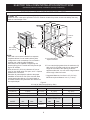
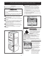
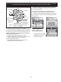
Anti-Tip Mounting Holes
Figure 6
6 Install the Anti-tip Mounting Screws
The wall oven can tip when the door is
open. The anti-tip mounting screws supplied with the
wall oven must be installed to prevent tipping of the
ZDOORYHQDQGLQMXU\WRSHUVRQV
A. The mounting holes in the side trims may be
used as a template to locate the appliance mounting
VFUHZKROHVVHH¿JXUH
%8VHWKHWZRVFUHZVVXSSOLHGWR¿[WKHDSSOLDQFH
to the cabinet.
Tip Over Hazard
• A child or adult can tip the oven
and be killed.
• Install the anti-tip device to oven
and/or structure per installation
instructions.
• Ensure the anti-tip device is re-engaged when the
oven is moved.
• Do not operate the oven without the anti-tip device
in place and engaged.
• Failure to follow these instructions can result in
death or serious burns to children and adults.
Refer to the installation
instructions supplied with your
appliance for proper installa-
tion.
Check for proper installation
with a visual check that the
anti-tip screws are present.
Test the installation with light
downward pressure on the
open oven door. The oven
should not tip forward.
Anti-tip mounting holes
+HDY\:HLJKW+D]DUG
• Use 2 or more people to move and install wall oven.
)DLOXUHWRIROORZWKLVLQVWUXFWLRQFDQUHVXOWLQLQMXU\RU
damage to the unit.
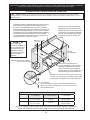
5. Cabinet Installation
Figure 5
1½" (3.8 cm)
clearance
between unit
1 Unpack the wall oven. Remove the bottom trim
taped on the oven top panel.
2 Find the 2 anti-tip mounting screws included in the
literature package.
3 Insert the oven into the cabinet opening. Slide oven
inward leaving 1½" (3.8 cm) clearance between the
oven and front of cabinet (see Figure 5).
4 Pull the armored cable through the hole for it in the
FDELQHWDQGWRZDUGWKHMXQFWLRQER[ZKLOHPRYLQJ
the appliance inward.
5 Push the oven in and against the cabinet.
Do not lift or manipulate the oven by the door handle
or the control panel.
IMPORTANT!

7
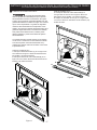
ELECTRIC WALL OVEN INSTALLATION INSTRUCTIONS
(with side-by-side and cooktop combination specialty installations)
A
B
A
B
Figure 7
7 Install the Bottom Trims
Bottom trims must be installed for
the oven to function properly. DO NOT operate the
oven without bottom oven trims installed. Do not use
wood or any other trim that is not manufactured for
use with this model. Operating the appliance without
manufacturer's bottom trims properly installed may
FDXVHSHUVRQDOLQMXU\DQGPD\GDPDJHFDELQHWU\RU
the appliance.
Screws to attach the bottom trim are supplied with
the oven. The trims are easier to install if the door
is removed. See the Use and Care Manual for
instructions on how to remove the oven door.
All 30" Models:
A. Place the air diverter (A) in place as shown in
Figure 7. Line up screw locations and attach both
ends.
B. Place the color matched trim (B) in place as
shown. Line up screw locations and attach both
ends.
All 27" Models:
A. Place the color matched trim (B) in place as
shown in Figure 8. Line up screw locations and
attach both ends.
B. Place the air diverter (A) in place as shown. Line
up screw locations and attach both ends.
A
B
A
B
Figure 8

8
ELECTRIC WALL OVEN INSTALLATION INSTRUCTIONS
(with side-by-side and cooktop combination specialty installations)
Figure 9.
27" and 30" Wall Ovens (Side by Side)
G
2”
(5.1 cm)
Min.
F
I
G
2”
(5.1 cm)
Min.
H
31”*
(78.7 cm)
1½” (3.8 cm)
Min.
3”
(7.6 cm)
B
A
D
C
27 1/4”
(69.2 cm)
J
2" (5 cm) Wide Wood
Spacer if Needed
Door Open
(see note 2)
Electrical
Junction Box
Hole for
Cord
Spacer
Do not remove spacers (if equipped) on the side walls of the built-in oven. These spacers
center the oven in the space provided. The oven must be centered to prevent excess heat buildup that may
UHVXOWLQKHDWGDPDJHRU¿UH
SINGLE WALL OVENS - SIDE-BY-SIDE INSTALLATION
All dimensions are in inches (cm).
NOTES:
1. Each wall oven must be installed in a separate,
complete cabinet. Do not install a side by side
FRQ¿JXUDWLRQXQGHUFRXQWHUWRSV'RQRWLQVWDOOD
cooktop over a side-by-side installation.
2. Each base must be capable of supporting 150
pounds (68 kg) for 27" models and 200 pounds (90
kg) for 30" models.
3. Allow at least 21" (53.3 cm) clearance in front of
oven for door depth when it is open, and 1" of space
between two oven doors.
4. Dimension G (cutout depth) is critical to the proper
installation of the built-in oven. If the oven trim does
not butt against the cabinet, or if noise is heard on
convection models, verify dimension G to assure it is
the required depth.
5. For a cutout height greater than the maximum (H),
add one 2"(5 cm) wide wood shim of appropriate
height to each side of the opening under the
appliance side rails. You can order a larger bottom
trim through a Service Center.
6XJJHVWHGGLVWDQFHIURPÀRRULVFP
Minimum required distance is 4 ½" (11.4cm).
PRODUCT DIMENSIONS
MODEL A B C D
27" (68.6 cm) 27 (68.6) 29
1
/
2
(74.9) 24
5
/
8
(62.5) 24
3
/
4
(62.9)
30" (76.2 cm) 30 (76.2) 29 (73.7) 28
1
/
4
(71.8) 24
3
/
4
(62.9)
CUTOUT DIMENSIONS AND CABINET WIDTH
FG
H
**Others, see notes 4 & 5
IJ
MODEL Min. Max. Min. Min. Max.
27" (68.6 cm) 24
7
/
8
(63.2) 25¼ (64.1)
24 (61.0)
27¼ (69.2) 28
1
/
4
(71.8) 28
3
/
8
(72.1) Min 3
1
/
8
(7.9) Min
30" (76.2 cm) 28
1
/
2
(72.4) 29 (73.7) 27¼ (69.2) 28
1
/
8
(71.4) 31
1
/
2
(80) Min 2
1
/
2
(6.4) Min

9
ELECTRIC WALL OVEN INSTALLATION INSTRUCTIONS
(with side-by-side and cooktop combination specialty installations)
Only certain cooktop models may be installed over certain
built-in electric oven models. Approved cooktops and built-in
ovens are listed by the MFG ID number and product code
(see the insert sheet included in the literature package and
cooktop installation instructions for dimensions). Do not
LQVWDOODVLGHE\VLGHFRQ¿JXUDWLRQXQGHUFRXQWHUWRSVRULQ
combination with a cooktop.
G
F
H
36” Min.
(91.4 cm) Min.
Use 3/4” (1.9 cm) plywood, installed on
WZRUXQQHUVÀXVKZLWKWRHSODWH%DVH
must be capable of supporting 150
pounds (68 kg) for 27" models and 200
pounds (90 kg) for 30" models.
Cut an opening in wood base minimum 9” x
´;FP´FPIURPOHIWVLGH¿OOHU
SDQHOWRURXWHDUPRUHGFDEOHWRMXQFWLRQER[
* If no cooktop is installed directly over
the oven unit, 5” (12.7 cm) maximum
LVDOORZHGDERYHWKHÀRRU
9ROWMXQFWLRQER[
for built-in oven.
Figure 10. TYPICAL UNDER COUNTER INSTALLATION OF A SINGLE ELECTRIC BUILT-IN
OVEN WITH AN ELECTRIC COOKTOP MOUNTED ABOVE
Approx. 3”
(7.5 cm)
&DELQHWVLGH¿OOHUSDQHOV
are necessary to isolate the
XQLWIURPDGMRLQLQJFDELQHWV
&DELQHWVLGH¿OOHUKHLJKW
should allow for installation of
approved cooktop models
To reduce the risk of
SHUVRQDOLQMXU\DQGWLS-
ping of the wall oven,
the wall oven must be
secured to the cabi-
net (s) by mounting
screws.
4 1/2” (11.5 cm) Max.*
CUTOUT DIMENSIONS AND CABINET WIDTH
F. WIDTH G. DEPTH H. HEIGHT
27" (68.6 cm)
24
7
/
8
" (63.2 cm) Min.
25
1
/
4
" (64.1 cm) Max.
24 (61.0)
27
1
/
4
(69.2) Min.
28
1
/
4
(71.8) Max.
30" (76.2 cm)
28
1
/
2
" (72.4 cm) Min.
29" (73.7 cm) Max.
24 (61.0)
27
1
/
4
(69.2) Min.
28
1
/
8
(71.4) Max.
TYPICAL UNDER-COUNTER INSTALLATION
Do not remove spacers (if equipped) on the side walls of the built-in oven. These spacers
center the oven in the space provided. The oven must be centered to prevent excess heat buildup that may
UHVXOWLQKHDWGDPDJHRU¿UH

10
ELECTRIC WALL OVEN INSTALLATION INSTRUCTIONS
(with side-by-side and cooktop combination specialty installations)
Figure 11. TYPICAL UNDER COUNTER INSTALLATION OF A SINGLE ELECTRIC BUILT-IN OVEN
WITH A GAS COOKTOP ABOVE
18”(45.7 cm) Max.
6 1/2” Min.
(16.5 cm)
Flare
Union
4”(10 cm)
9+]
Grounded
Outlet
Right Side
of Cabinet
(To be
accessible
IRUVKXWRႇ
valve
operation)
Pressure
Regulator
Manual
6KXWRႇ
Valve
Flexible Appliance Conduit
Cabinet sides or
¿OOHUSDQHO
Wall Oven Cabinet
5” Max.
(12.7 cm)
Flare
Union
7. Checking Operation
Your model is equipped with an Electronic Oven
Control. Each of the functions has been factory
checked before shipping. However, it is suggested
that you verify the operation of the electronic oven
controls once more. Refer to the Use and Care Guide
for operation.
1. Remove all items from the inside of the oven.
2. Turn on the power to the oven (Refer to your Use &
Care Guide.)
3. Verify the operation of the electronic oven controls:
Bake– Verify that this function makes the oven hot.
20 seconds after turning oven on, open the door and
you should feel heat coming from the oven.
Broil– When the oven is set to BROIL, the upper
element in the oven should become red.
Convection (some models)–When the oven is set for
a convection baking or roasting, both elements cycle
RQDQGRႇDOWHUQDWHO\DQGWKHFRQYHFWLRQIDQZLOOUXQ
The convection fan will stop running when the oven
door is opened.
Before You Call for Service
Read the "Before You Call for Service Checklist" and
the "Operating Instructions" in your Use and Care
Guide. It may save you time and expense. The list
includes common occurrences that are not the result of
defective workmanship or materials in this appliance.
Refer to your Use and Care Guide for service phone
numbers.
IMPORTANT NOTE
A cooling fan inside the upper rear part above the
oven (some models) provides cooling of the oven
electrical and electronic components. If the oven
has been operating at high temperatures, the fan
ZLOOFRQWLQXHWRUXQDIWHUWKHRYHQLVWXUQHGRႇ
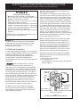
6. Leveling the Wall Oven
1. Install an oven rack in the center of the upper oven
(see Figure 12).
2. Place a level on the rack. Take 2 readings with the
level placed diagonally in one direction and then
the other. Use wood shims under the wall oven to
level if necessary.
3. Repeat in the lower
oven if you have a
double cavity wall
oven. If the level
indicates that the rack
is not level, use wood
shims to reach a
compromise for both
ovens.
Figure 12
Page is loading ...
Page is loading ...
Page is loading ...
Page is loading ...
Page is loading ...
Page is loading ...
Page is loading ...
Page is loading ...
Page is loading ...
Page is loading ...
Page is loading ...
Page is loading ...
Page is loading ...
Page is loading ...
Page is loading ...
Page is loading ...
Page is loading ...
Page is loading ...
Page is loading ...
Page is loading ...
Page is loading ...
Page is loading ...
-
 1
1
-
 2
2
-
 3
3
-
 4
4
-
 5
5
-
 6
6
-
 7
7
-
 8
8
-
 9
9
-
 10
10
-
 11
11
-
 12
12
-
 13
13
-
 14
14
-
 15
15
-
 16
16
-
 17
17
-
 18
18
-
 19
19
-
 20
20
-
 21
21
-
 22
22
-
 23
23
-
 24
24
-
 25
25
-
 26
26
-
 27
27
-
 28
28
-
 29
29
-
 30
30
-
 31
31
-
 32
32


Frigidaire FGEW3066UFB Installation guide
- Category
- Ovens
- Type
- Installation guide
Ask a question and I''ll find the answer in the document
Finding information in a document is now easier with AI
in other languages
Related papers
-
Frigidaire FGEW3066UD Installation guide
-
Frigidaire FGEW2766UD Installation guide
-
-
Frigidaire FGEW276SPF User manual
-
Frigidaire FGMC3066UF Installation guide
-
Frigidaire FGMC3065PF Installation guide
-
Frigidaire FGMC2766UF Installation guide
-
Frigidaire FCWM2727AS User manual
-
-
Kenmore Elite EI30EW38TS Installation guide
Other documents
-
 Kenmore Elite 79048863810 Installation guide
-
Electrolux ECWD3011AS Installation guide
-
Kenmore 49619 Installation guide
-
Electrolux EW30EW55PS Installation guide
-
-
Jenn-Air JJW8630DDB User manual
-
Electrolux EW27EW55GB - 27 Inch Single Electric Wall Oven User guide
-
Haier HCW3460AES Installation guide
-
Fulgor F4SP30S1 Installation guide
-
