Electrolux ECWD3011AS Installation guide

Category
Microwaves
Type
Installation guide

This manual is also suitable for

1
ELECTRIC WALL OVEN INSTALLATION INSTRUCTIONS
(with cooktop combination installations)
Figure 1
30" Single Wall Ovens
PN 807153707 Rev. A (2020/10)
English – pages 1-10
Español – páginas 11-20
Français – pages 21-30
All dimensions are in inches (cm).
Do not remove spacers (if equipped) on the side walls of the built-in oven. These spacers
center the oven in the space provided. The oven must be centered to prevent excess heat buildup that may
result in heat damage or re.
NOTES:
1. Allow at least 21"
(53.3 cm) clearance in
front of oven for door
depth when it is open.
2. Dimension G (cutout depth)
is critical to the proper
installation of the built-in
oven. If the oven trim does
not butt against the cabinet,
or if noise is heard on
convection models, verify
dimension G to assure it is
the required depth.
3. For a cutout height
greater than the maximum
(H), add one 2"(5 cm)
wide wood shim of
appropriate height to each
side of the opening under
the appliance side rails
(not included).
Printed in U.S.A.
INSTALLATION AND SERVICE MUST BE PERFORMED BY A QUALIFIED INSTALLER.
IMPORTANT: SAVE FOR LOCAL ELECTRICAL INSPECTOR'S USE.
READ AND SAVE THESE INSTRUCTIONS FOR FUTURE REFERENCE.
FOR YOUR SAFETY: Do not store or use gasoline or other
ammable vapors and liquids in the vicinity of this or any other appliance.
Your new wall oven has been designed to t a variety of cutout sizes to make the job of installing easier. The rst
step of your installation should be to measure your current cutout dimensions and compare them to the cutout
dimensions chart below for your model. You may nd little or no cabinet work being necessary.
PRODUCT DIMENSIONS
A B C D
30 (76.2 cm) 29
1
/
8
(73.9 cm) 28
1
/
4
(71.8 cm) 25
3
/
16
(63.9 cm)
CUTOUT DIMENSIONS AND CABINET WIDTH
F G
H. Standard Height
(**Others, see note 3)
I
Min. Max. Min. Min. Max.
28
1
/
2
(72.4 cm) 29 (73.7 cm) 24 (61.0 cm) 27¼ (68.8 cm) 28
1
/
8
(71.4 cm) 30
1
/
8
(76.5 cm) Min
United States
and Canada
Hole for
Cord
Electrical
Junction Box
2" (5 cm) Wide Wood
Spacer if Needed
B
B
A
A
D
D
C
C
H
H
F
F
I
I
G
G
27 1/4”
(68.8 cm)
2”
(5.1 cm)
Min.
31”*
(78.7 cm)
)
3”
(7.6 cm)
1½” (3.8 cm)
Min.
Door Open
(see note 2)
Spacer
SINGLE WALL OVEN - SINGLE INSTALLATION
* Suggested distance from oor is 31" (78.7cm).
Minimum required distance is 4 ½" (11.4cm).
2
ELECTRIC WALL OVEN INSTALLATION INSTRUCTIONS
(with cooktop combination installations)
Figure 2
30" Double Wall Ovens
Do not remove spacers (if equipped) on the side walls of the built-in oven. These spacers
center the oven in the space provided. The oven must be centered to prevent excess heat buildup that may
result in heat damage or re.
NOTES:
1. Allow at least 21" (53.3 cm) clearance in front of
oven for door depth when it is open.
2. Dimension G (cutout depth) is critical to the
proper installation of the built-in oven. If the oven
trim does not butt against the cabinet, or if noise
is heard on convection models, verify dimension
G to assure it is according to the required
dimension.
3. For a cutout height greater than 49
3
/
4
" (126.4cm),
add one 2"(5 cm) wide wood shim of appropriate
height to each side of the opening under the
appliance side rails (not included).
All dimensions are in inches (cm).
B
B
A
A
D
D
F
F
I
I
H
H
G
G
C
C
48 5/8”
(124.1 cm)
11½”
(29.2 cm)
2”
(5.1 cm)
Min.
3” (7.6 cm
)
Max.
1½” (3.8 cm)
Min.
Door Open
(see note 2)
Hole for
Cable
Electrical
Junction Box
2" (5 cm) Wide Wood
Spacer if Needed
Spacer
PRODUCT DIMENSIONS
A B C D
30 (76.2 cm) 50
13
/
16
(129.0 cm) 28
1
/
4
(71.8 cm) 25
3
/
16
(63.9 cm)
CUTOUT DIMENSIONS AND CABINET WIDTH
F G (Min.)
H. Standard Height
(**Others, see notes 3)
I
Min. Max. Min. Max.
28
1
/
2
(72.4 cm) 29 (73.7 cm) 24 (61.0 cm) 48
7
/
8
(124.5 cm) 50
1
/
4
(127.6 cm) 30
1
/
8
(76.5 cm) Min
DOUBLE WALL OVEN INSTALLATION
3
ELECTRIC WALL OVEN INSTALLATION INSTRUCTIONS
(with cooktop combination installations)
Single Wall Ovens
1. Base must be capable of supporting 200 pounds
(90 kg).
2. Solid plywood or solid wood must be at least ½”
(1.3 cm) thick.
Double Wall Ovens
1. Base must be capable of supporting 375 pounds
(170 kg).
2. Solid plywood or solid wood must be at least ¾”
(1.9 cm) thick.
CARPENTRY and SUPPORT
Refer to Figure 1 or Figure 2 for the dimensions of your appliance and the cabinet cutouts and space needed
to t the oven.
The oven support or base surface must be solid plywood, solid wood, or a material veried to meet the
temperature and strength requirements needed for your installation. No berboard, laminated/coated wood or
other material should be used that is not veried to meet temperature and strength requirements.
All materials used in installation must withstand temperatures of 194 °F (90 °C).
The support surface must be level and at from side to side, and from front to rear.
If the cabinet does not have a solid oor or support surface, braces may be installed in the cabinet. Bracing
may also be used under the cabinet oor for added strength and support. Braces must run front to rear, meet
all material and temperature requirements, and be at and level. The bracing should be 2" (5 cm) minimum
width to support the oven side rails. Standard 2" x 4" (5 cm x 10 cm) studs are recommended.
Figure 3
Wall Oven Braces
4
ELECTRIC WALL OVEN INSTALLATION INSTRUCTIONS
(with cooktop combination installations)
Important Notes to the Installer
1. Read all instructions contained in these installation
instructions before installing the wall oven.
2. Remove all packing material from the oven
compartments before connecting the electrical
supply to the wall oven.
3. Observe all governing codes and ordinances.
4. Be sure to leave these instructions with the
consumer.
5. Remove oven door to facilitate installation. See Use
and Care guide for instructions.
6. THESE OVENS ARE NOT APPROVED FOR
STACKABLE OR SIDE-BY-SIDE INSTALLATION.
Important Note to the Consumer
Keep these instructions with your Owner's Guide for the
local electrical inspector's use and future reference.
IMPORTANT SAFETY
INSTRUCTIONS
Be sure your wall oven is installed and grounded
properly by a qualied installer or service technician.
This wall oven must be electrically grounded in
accordance with local codes or, in their absence,
with the National Electrical Code ANSI/NFPA No.70-
latest edition in United Sates, or with CSA Standard
C22.1, Canadian Electrical Code, Part 1, in Canada.
Stepping, leaning or sitting on the door
of this wall oven can result in serious injuries and can
also cause damage to the wall oven.
Never use your wall oven for warming or heating
the room. Prolonged use of the wall oven without
adequate ventilation can be dangerous.
The electrical power to the oven must be
shut o while line connections are being made. Failure to
do so could result in serious injury or death.
1. Electrical Requirements
Each appliance must be supplied with the proper
voltage and frequency, and connected to an individual,
properly grounded branch circuit, protected by a circuit
breaker or fuse. To know the circuit breaker or fuse
required by your model, see the serial plate to nd the
wattage consumption and refer to table A to get the
circuit breaker or fuse amperage.
Table A
Observe all governing codes and local ordinances
1. A 3-wire or 4-wire single phase 120/240 or 120/208
Volt, 60 Hz AC only electrical supply is required on
a separate circuit fused on both sides of the line
(red and black wires). A time-delay fuse or circuit
breaker is recommended. DO NOT fuse neutral
(white wire). Only certain cooktop models may be
installed over certain built-in electric oven models.
Approved cooktops and built-in ovens are listed by
the MFG ID number (see the insert sheet included in
the literature package). Do not install a cooktop over
a side-by-side wall oven installation.
NOTE: Wire sizes and connections must conform with
the fuse size and rating of the appliance in accordance
with the American National Electrical Code ANSI/NFPA
No. 70-latest edition, or with Canadian CSA Standard
C22.1, Canadian Electrical Code, Part 1, and local
codes and ordinances.
An extension cord should not be used
with this appliance. Such use may result in a re,
electrical shock, or other personal injury. If you need a
longer power cord you can purchase a 10' (3 m) power
cord kit #903056-9010 by calling the Service Center.
2. These appliances should be connected to the
fused disconnect (or circuit breaker) box through
exible armored or nonmetallic sheathed cable.
The exible armored cable extending from the
appliance should be connected directly to the
junction box. The junction box should be located
as shown in Figure 1 or Figure 2 and with as much
slack as possible remaining in the cable between
the box and the appliance, so it can be moved if
servicing is ever necessary.
3. A suitable strain relief must be provided to attach
the exible armored cable to the junction box.
Appliance
Rating Watts
240V
Protection
Circuit
Recommended
Appliance
Rating Watts
208V
Protection
Circuit
Recommended
Less than
4800W
20A
Less than
4100W
20A
4801W - 7200W
30A
4101W - 6200W
30A
7201W - 9600W
40A or 50A
6201W - 8300W
40A or 50A
9601W and +
50A
8301W and +
50A
5
ELECTRIC WALL OVEN INSTALLATION INSTRUCTIONS
(with cooktop combination installations)
In cold weather shipping and storage
conditions, make sure that oven is in nal location
at least three (3) hours before switching on power.
Switching on power while oven is still cold may
damage the oven controls.
2. Electrical connection
It is the responsibility and obligation of the consumer to
contact a qualied installer to assure that the electrical
installation is adequate and is in conformance
with the National Electrical Code ANSI/NFPA No.
70-latest edition, or with CSA Standard C22.1,
Canadian Electrical Code, Part 1, and local codes and
ordinances.
Risk of electrical shock (Failure to
heed this warning may result in electrocution or
other serious injury.) This appliance is equipped with
copper lead wire. If connection is made to aluminum
house wiring, use only connectors that are approved
for joining copper and aluminum wire in accordance
with the National Electrical Code and local code and
ordinances. When installing connectors having screws
which bear directly on the steel and/or aluminum
exible conduit, do no tighten screws suciently to
damage the exible conduit. Do not over bend or
excessively distort exible conduit to avoid separation
of convolutions en exposure of internal wires.
DO NOT ground to a gas supply pipe. DO NOT
connect to electrical power supply until appliance
is permanently grounded. Connect the ground wire
before turning on the power.
(If your appliance is equipped with a
white neutral conductor.)
This appliance is manufactured with a white neutral
power supply and a frame connected copper wire. The
frame is grounded by connection of grounding lead to
neutral lead at the termination of the conduit, if used in
USA, in a new branch circuit installation (1996 NEC),
mobile home, recreational vehicles, where local code
do not permit grounding trough the neutral (white) wire
or in Canada, disconnect the white and green lead
from each other and use ground lead to ground unit in
accordance with local codes, connect neutral lead to
branch circuit-neutral conductor in usual manner see
Figure 5. If your appliance is to be connected to a 3
wire grounded junction box (US only), where local code
permit connecting the appliance-grounding conductor
to the neutral (white) see Figure 4.
NOTE TO ELECTRICIAN: The armored cable leads
supplied with the appliance are UL-recognized for
connection to larger gauge household wiring. The
insulation of the leads is rated at temperatures much
higher than temperature rating of household wiring.
The current carrying capacity of the conductor is
governed by the temperature rating of the insulation
around the wire, rather than the wire gauge alone.
Where local codes permit connecting the appliance-
grounding conductor to the neutral (white) wire (US
Only) (see Figure 4):
1. Disconnect the power supply.
2. In the junction box:
connect appliance and power supply cable wires as
shown in Figure 4.
Electrical Shock Hazard
Electrical ground is required on this appliance.
Do not connect to the electrical supply until
appliance is permanently grounded.
Disconnect power to the junction box before
making the electrical connection.
This appliance must be connected to a grounded,
metallic, permanent wiring system, or a grounding
connector should be connected to the grounding
terminal or wire lead on the appliance.
Do not use a gas supply line for grounding the
appliance.
Failure to do any of the above could result in a re,
personal injury or electrical shock.
Figure 4
3-WIRE GROUNDED JUNCTION BOX
Cable from Power Supply
Black
Wires
Junction
Box
Cable from appliance
Ground Wire
(Bare or Green Wire)
White Wire
(Neutral)
U.L.-Listed Conduit
Connector (or CSA listed)
Red
Wires
White Wire
(Neutral)
6
ELECTRIC WALL OVEN INSTALLATION INSTRUCTIONS
(with cooktop combination installations)
Model and Serial Number Location
The serial plate is located along the interior side trim of
the oven and visible when the door is opened.
When ordering parts for or making inquires about your
oven, always be sure to include the model and serial
numbers and a lot number or letter from the serial plate
on your oven.
Single Wall Oven
Serial Plate Location
Double Wall Oven
Serial Plate Location
If oven is used in a new branch circuit installation
(1996 NEC), mobile home, recreational vehicle, or
where local codes DO NOT permit grounding through
the neutral (white) wire, the appliance frame MUST
NOT be connected to the neutral wire of the 4-wire
electrical system (see Figure 5):
1. Disconnect the power supply.
2. Separate the green (or bare copper) and white
appliance cable wires.
3. In the junction box:
connect appliance and power supply cable wires as
shown in Figure 5.
Figure 5
4-WIRE GROUNDED JUNCTION BOX
Cable from Power Supply
White Wire
Junction Box
Cable from appliance
White Wire
Black
Wires
Red
Wires
Ground Wire
Ground Wire
(Bare or Green
Wire)
U.L.-Listed
Conduit Connector
(or CSA listed)
Figure 6
7
ELECTRIC WALL OVEN INSTALLATION INSTRUCTIONS
(with cooktop combination installations)
Anti-Tip Mounting Holes
Figure 8
6 Install the Anti-tip Mounting Screws
The wall oven can tip when the door is
open. The anti-tip mounting screws supplied with the
wall oven must be installed to prevent tipping of the
wall oven and injury to persons.
A. The mounting holes in the side trims may be
used as a template to locate the appliance mounting
screw holes (see gure 8).
B. Use the two screws supplied to x the appliance
to the cabinet.
Tip Over Hazard
A child or adult can tip the oven
and be killed.
• Install the anti-tip device to oven
and/or structure per installation
instructions.
• Ensure the anti-tip device is re-engaged when the
oven is moved.
• Do not operate the oven without the anti-tip device
in place and engaged.
• Failure to follow these instructions can result in
death or serious burns to children and adults.
Refer to the installation
instructions supplied with your
appliance for proper installa-
tion.
Check for proper installation
with a visual check that the
anti-tip screws are present.
Test the installation with light
downward pressure on the
open oven door. The oven
should not tip forward.
Anti-tip mounting holes
Heavy Weight Hazard
Use 2 or more people to move and install wall oven.
Failure to follow this instruction can result in injury or
damage to the unit.
3. Cabinet Installation
1½" (3.8 cm)
clearance
between unit
1 Unpack the wall oven. Remove the bottom trim
taped on the oven top panel.
2 Find the 2 anti-tip mounting screws included in the
literature package.
3 Insert the oven into the cabinet opening. Slide oven
inward leaving 1½" (3.8 cm) clearance between the
oven and front of cabinet (see Figure 7).
4 Pull the armored cable through the hole for it in the
cabinet and toward the junction box while moving
the appliance inward.
5 Push the oven in and against the cabinet.
Do not lift or manipulate the oven by the door handle
or the control panel.
IMPORTANT!
Figure 7
8
ELECTRIC WALL OVEN INSTALLATION INSTRUCTIONS
(with cooktop combination installations)
A
B
A
B
Figure 9
7 Install the Bottom Trims
Bottom trims must be installed for
the oven to function properly. DO NOT operate the
oven without bottom oven trims installed. Do not use
wood or any other trim that is not manufactured for
use with this model. Operating the appliance without
manufacturer's bottom trims properly installed may
cause personal injury and may damage cabinetry or
the appliance.
Screws to attach the bottom trim are supplied with
the oven. The trims are easier to install if the door
is removed. See the Use and Care Manual for
instructions on how to remove the oven door.
All 30" Models:
A. Place the air diverter (A) in place as shown in
Figure 9. Line up screw locations and attach both
ends.
B. Place the color matched trim (B) in place as
shown. Line up screw locations and attach both
ends.
9
ELECTRIC WALL OVEN INSTALLATION INSTRUCTIONS
(with cooktop combination installations)
Only certain cooktop models may be installed over certain
built-in electric oven models. Approved cooktops and built-in
ovens are listed by the MFG ID number and product code
(see the insert sheet included in the literature package and
cooktop installation instructions for dimensions). Do not
install a side-by-side conguration under countertops, or in
combination with a cooktop.
G
F
H
36” Min.
(91.4 cm) Min.
Use 3/4” (1.9 cm) plywood, installed on
two runners, ush with toe plate. Base
must be capable of supporting 200
pounds (90 kg).
Cut an opening in wood base minimum 9” x 9”
(23 X 23 cm), 2” (5 cm) from left side ller pan-
el, to route armored cable to junction box.
* If no cooktop is installed directly over
the oven unit, 5” (12.7 cm) maximum
is allowed above the oor.
208/240 Volt junction box
for built-in oven.
Figure 10. TYPICAL UNDER COUNTER INSTALLATION OF A SINGLE ELECTRIC BUILT-IN
OVEN WITH AN ELECTRIC COOKTOP MOUNTED ABOVE
Approx. 3”
(7.5 cm)
Cabinet side ller panels
are necessary to isolate the
unit from adjoining cabinets.
Cabinet side ller height
should allow for installation of
approved cooktop models
To reduce the risk of
personal injury and tip-
ping of the wall oven,
the wall oven must be
secured to the cabi-
net (s) by mounting
screws.
4 1/2” (11.5 cm) Max.*
CUTOUT DIMENSIONS AND CABINET WIDTH
F. WIDTH G. DEPTH H. HEIGHT
30" (76.2 cm)
28
1
/
2
" (72.4 cm) Min.
29" (73.7 cm) Max.
24 (61.0)
27
1
/
4
(69.2) Min.
28
1
/
8
(71.4) Max.
TYPICAL UNDER-COUNTER INSTALLATION
Do not remove spacers (if equipped) on the side walls of the built-in oven. These spacers
center the oven in the space provided. The oven must be centered to prevent excess heat buildup that may
result in heat damage or re.
10
ELECTRIC WALL OVEN INSTALLATION INSTRUCTIONS
(with cooktop combination installations)
Figure 11. TYPICAL UNDER COUNTER INSTALLATION OF A SINGLE ELECTRIC BUILT-IN OVEN
WITH A GAS COOKTOP ABOVE
18”(45.7 cm) Max.
6 1/2” Min.
(16.5 cm)
Flare
Union
4”(10 cm)
120V/60Hz
Grounded
Outlet
Right Side
of Cabinet
(To be
accessible
for shut-o
valve
operation)
Pressure
Regulator
Manual
Shuto
Valve
Flexible Appliance Conduit
Cabinet sides or
ller panel
Wall Oven Cabinet
5” Max.
(12.7 cm)
Flare
Union
5. Checking Operation
Your model is equipped with an Electronic Oven
Control. Each of the functions has been factory
checked before shipping. However, it is suggested
that you verify the operation of the electronic oven
controls once more. Refer to the Use and Care Guide
for operation.
1. Remove all items from the inside of the oven.
2. Turn on the power to the oven (Refer to your Use &
Care Guide.)
3. Verify the operation of the electronic oven controls:
Bake– Verify that this function makes the oven hot.
20 seconds after turning oven on, open the door and
you should feel heat coming from the oven.
Broil– When the oven is set to BROIL, the upper
element in the oven should become red.
Convection (some models)–When the oven is set for
a convection baking or roasting, both elements cycle
on and o alternately and the convection fan will run.
The convection fan will stop running when the oven
door is opened.
Before You Call for Service
Read the "Before You Call for Service Checklist" and
the "Operating Instructions" in your Use and Care
Guide. It may save you time and expense. The list
includes common occurrences that are not the result of
defective workmanship or materials in this appliance.
Refer to your Use and Care Guide for service phone
numbers.
IMPORTANT NOTE
A cooling fan inside the upper rear part above the
oven (some models) provides cooling of the oven
electrical and electronic components. If the oven
has been operating at high temperatures, the fan
will continue to run after the oven is turned o.
4. Leveling the Wall Oven
1. Install an oven rack in the center of the upper oven
(see Figure 12).
2. Place a level on the rack. Take 2 readings with the
level placed diagonally in one direction and then
the other. Use wood shims under the wall oven to
level if necessary.
3. Repeat in the lower
oven if you have a
double cavity wall
oven. If the level
indicates that the rack
is not level, use wood
shims to reach a
compromise for both
ovens.
Figure 12
11
INSTRUCCIONES DE INSTALACIÓN PARA EL HORNO ELÉCTRICO DE PARED
(con instrucciones para la instalación de la estufa)
B
B
A
A
D
D
C
C
H
H
F
F
I
I
G
G
27 1/4”
(68.8 cm)
2”
(5.1 cm)
Min.
31”*
(78.7 cm)
)
3”
(7.6 cm)
1½” (3.8 cm)
Min.
Espaciador de Madera de 2"
(5 cm) de ancho, si es necesario
Oricio
para el
Cable
Espaciador
Caja eléctrica
de empalme
Puerta Abierta
(vea la nota 2)
Figura 1: Hornos simples de Pared de 30"
P/N 807153707 (2020/10) Rev. A
English – pages 1-10
Español – páginas 11-20
Français - pages 21-30
No quite los separadores de los muros laterales del horno empotrado. Estos espaciadores
centran el horno en el espacio provisto. El horno debe estar centrado para prevenir una concentración excesiva
de calor que podría resultar en daños por el calor o un incendio.
NOTAS:
1. Deje por lo menos 21"
(53.3 cm) de espacio libre para
la profundidad de la puerta
cuando esta abierta.
2. La dimensión G (profundidad
del corte) está primordial
para instalar correctamente el
horno de pared. Si el adorno
del armazón del horno no
topa contra el armario, o si
escuche un ruido, verique
si la dimensión G está en
conformidad con la dimensión
requerida.
3. Para un corte de altura superior
al máximo (H), agregue una
cuña de madera de 2 "(5 cm)
de ancho para lograr la altura
adecuada en cada lado del
oricio ubicado debajo de los
rieles laterales del accesorio (no
incluido).
Todas las dimensiones se dan en pulgadas
(cm). Imprimido en U.S.A.
PARA SU SEGURIDAD: No almanece ni utilice gasolina u otros vapores y líquidos
inamables en la proximidad de este o de cualquier otro artefacto.
Su nuevo horno de pared ha sido diseñado para adaptarse a una variedad de tamaños de corte
para facilitar el trabajo de instalación. El primer paso para su instalación debe de ser el de medir
las dimensiones de la apertura y compararlas con las que se indican en el cuadro de dimensiones
del hueco de la gura 1. Posiblemente encontrará que algún trabajo de carpintería será necesario.
LA INSTALACIÓN Y EL SERVICIO DEBEN SER EFECTUADOS POR UN INSTALADOR CALIFICADO.
IMPORTANTE: GUARDE ESTAS INSTRUCCIONES PARA USO DEL INSPECTOR LOCAL DE
ELECTRICIDAD. LEA Y GUARDE ESTAS INSTRUCCIONES PARA REFERENCIA FUTURA.
Estados Unidos
y Canadá
HORNO DE PARED SIMPLE - INSTALACIÓN INDIVIDUAL
* Distancia sugerida desde el suelo es 31" (78.7 cm).
La distancia mínima requerida es 4½" (11.4 cm).
DIMENSIONES DEL APARATO
A B C D
30 (76.2 cm) 29
1
/
8
(73.9 cm) 28
1
/
4
(71.8 cm) 25
3
/
16
(63.9 cm)
DIMENSIONES DEL HUECO Y ANCHURA DEL ARMARIO
F G
H. Altura estándar
(**Otras, vea nota 3)
I
Min. Max. Min. Min. Max.
28
1
/
2
(72.4 cm) 29 (73.7 cm) 24 (61.0 cm) 27¼ (68.8 cm) 28
1
/
8
(71.4 cm) 30
1
/
8
(76.5 cm) Min
12
INSTRUCCIONES DE INSTALACIÓN PARA EL HORNO ELÉCTRICO DE PARED
(con instrucciones para la instalación de la estufa)
Figura 2: HORNOS DOBLES DE 30"
Todas las dimensiones se dan en pulgadas (cm).
NOTES:
1. Deje por lo menos 21" (53.3 cm) de espacio libre
para la profundidad de la puerta cuando esta
abierta.
2. La dimensión G (profundidad del corte) está
primordial para instalar correctamente el horno de
pared. Si el adorno del armazón del horno no topa
contra el armario, o si escuche un ruido, verique
si la dimensión G está en conformidad con la
dimensión requerida.
3. Para un corte de una profundidad mayor que 49
3
/
4
"
(126.5 cm), agregar una cuña de madera de 2"
(5 cm) de ancho para lograr la altura apropiada a
cada lado del oricio ubicado debajo de los rieles
laterales del accesorio (no incluidos).
No quite los separadores de los muros laterales del horno empotrado. Estos espaciadores
centran el horno en el espacio provisto. El horno debe estar centrado para prevenir una concentración excesiva
de calor que podría resultar en daños por el calor o un incendio.
BB
AA
DD
FF
II
HH
GG
CC
48 5/8”
(123.5 cm)
48 5/8”
(123.5 cm)
11½”
(29.2 cm)
11½”
(29.2 cm)
2”
(5.1 cm)
Min.
2”
(5.1 cm)
Min.
3” (7.6 cm)
Max.
3” (7.6 cm)
Max.
1½” (3.8 cm)
Min.
1½” (3.8 cm)
Min.
Puerta Abierta
(vea la nota 2)
Espaciador
Caja eléctrica de
empalme
Oricio
para el
Cable
Espaciador de Madera
de 2" (5 cm) de ancho, si
es necesario
DIMENSIONES DEL APARATO
A B C D
30 (76.2 cm) 50
13
/
16
(129.0 cm) 28
1
/
4
(71.8 cm) 25
3
/
16
(63.9 cm)
DIMENSIONES DEL HUECO Y ANCHURA DEL ARMARIO
F G (Min.) H. Altura estándar
(**Otras, vea nota 3)
I
Min. Max. Min. Max.
28
1
/
2
(72.4 cm) 29 (73.7 cm) 24 (61.0 cm) 48
7
/
8
(124.5 cm) 50
1
/
4
(127.6 cm) 30
1
/
8
(76.5 cm) Min
13
INSTRUCCIONES DE INSTALACIÓN PARA EL HORNO ELÉCTRICO DE PARED
(con instrucciones para la instalación de la estufa)
Hornos de pared simple
1. La base debe ser capaz de soportar 200 lb
(90 kg).
2. La madera contrachapada o la madera maciza
debe tener un grosor mínimo de ½” (1.3 cm).
Hornos de pared doble
1. La base debe ser capaz de soportar 375 lb
(170 kg).
2. La madera contrachapada o la madera maciza
debe tener un grosor mínimo de ¾” (1.9 cm).
ESPACIO y ESTRUCTURAS DE APOYO
Consulte la gura 1 o la gura 2 para determinar las dimensiones del aparato, el espacio del gabinete y el
espacio necesario para colocar el horno.
La estructura de apoyo del horno o la supercie de la base debe ser de madera contrachapada (plywood), de
madera maciza o de un material en el que se hayan constatado los requisitos de temperatura y resistencia
necesarios para la instalación. No se deben utilizar paneles de bra, madera laminada/recubierta ni ningún
otro material donde no se constaten los requisitos de temperatura y resistencia.
Todos los materiales que se utilizaron para la instalación deben soportar temperaturas de 194° F (90 °C).
La supercie de apoyo debe ser plana y debe estar nivelada en todos sus lados: derecha/izquierda, delante/
detrás.
Si el gabinete no tiene un piso sólido o una supercie de apoyo, pueden instalarse soportes en el gabinete.
Además, se pueden utilizar debajo del piso del gabinete para brindar mayor apoyo y resistencia. Los soportes
deben ir de adelante hacia atrás y cumplir con todos los requisitos de material y temperatura, deben ser
planos y estar nivelados. Deben tener un ancho mínimo de 2” (5 cm) para soportar los rieles laterales del
horno. Se recomienda utilizar montantes de 2” x 4” (5 cm x 10 cm).
Figure 3
Soportes Para Horno de Pared
14
INSTRUCCIONES DE INSTALACIÓN PARA EL HORNO ELÉCTRICO DE PARED
(con instrucciones para la instalación de la estufa)
Notas importantes para el instalador
1. Lea todas las instrucciones contenidas en este
manual antes de instalar el horno.
2. Saque todo el material usado en el embalaje del
compartimiento del horno antes de conectar el
suministro eléctrico o de gas a la estufa.
3. Observe todos los códigos y reglamentos pertinentes.
4. Deje estas instrucciones con el consumidor.
5. Retire la puerta del horno para facilitar la instalación.
Consulte la guía de uso y cuidado para obtener
instrucciones.
6. ESTE HORNO NO ESTÁ APROBADO PARA LA
INSTALACIÓN APILABLE O DE LADO A LADO.
Nota importante al consumidor
Conserve estas instrucciones y el manual del usuario para
uso del inspector local de electricidad y referencia futura.
INSTRUCCIONES IMPORTANTES DE
SEGURIDAD
• Asegúrese de que su horno de pared sea instalado y
puesto a tierra de forma apropiada por un instalador
calicado o por un técnico de servicio.
Este horno de pared debe ser eléctricamente puesto
a tierra de acuerdo con los códigos locales o, en su
ausencia, con el Código Eléctrico Nacional ANSI/
NFPA No. 70–última edición en los Estados Unidos,
o el Código Eléctrico Canadiense CSA Standard
C22.1, Part 1, en Canadá.
Pisar, apoyarse, o sentarse sobre la
puerta de este horno de pared puede causar serias
lesiones y daños al horno de pared.
Nunca use su horno de pared para
calentar una habitación. El uso prolongado de la estufa
sin la ventilación adecuada puede ser peligroso.
La corriente eléctrica al horno debe
estar apagada mientras se hacen las conexiones
de líneas. Si no se apaga, daños serios o la muerte
podrían resultar.
1. Requerimientos Eléctricos
Se debe proveer el voltaje y la frecuencia apropiados a
este electrodoméstico, y conectarse a un circuito individual
correctamente puesto a tierra, protegido por un interruptor
o un fusible. Para conocer el interruptor o fusible que
requiere su modelo, vea la placa serial para encontrar
la consumación del vatiaje y reérase al cuadro A para
encontrar el amperaje del interruptor o fusible.
Table A
Observe todos los códigos que gobiernan y ordenanzas
locales
1. Un cable de 3 o 4 alambres monofásico 120/240 o
120/208 voltios, 60 hertzios es la única fuente eléctrica
que requiere en un circuito separado en ambos lados de
la línea (alambre negro y alambre rojo) (se recomienda
un fusible o un interruptor de retraso de tiempo). No
funda a cable neutro (alambre blanco). Se debe de
tener precaución al combinar un horno de pared y una
cubierta, reérase a la placa de seria de cada uno de
los aparatos. No instale una estufa sobre una instalación
de horno de pared de lado a lado.
NOTA: Los tamaños y las conexiones del alambre deben
conformarse con el tamaño del fusible y el grado de la
aplicación de acuerdo con el código Eléctrico Nacional
Americano ANSI/NFPA No. 70- ultima edición, o con
el estándar CSA canadiense C22.1, código eléctrico
canadiense, parte 1, y códigos y ordenanzas locales.
No se debera usar extensiones para
enchufar este electrodoméstico. Esto podría causar
un incendio, choque eléctrico u otro tipo de daño
personal. Si usted necesita un cable mas largo, puede
ordenar un cable de 10" kit 903056-9010 llamando al
centro de Servicio.
2. Este electrodoméstico debe conectarse a la caja
de fusibles (o de cortocircuito), por medio de un
cable blindado exible o un cable con forro no
metálico. El cable blindado exible que va desde
el electrodoméstico debe de estar conectado
directamente a la caja de empalme. La caja de
empalme debe de estar localizada en el lugar
que se indica en la Figura 1 o 2, dejando tanto
exceso de cable como sea posible entre la
caja y el electrodoméstico, de forma que así el
electrodoméstico se pueda mover fácilmente, si fuera
necesario para hacer una reparación.
3. Se debe de usar un conector que reduzca la tirantez
de una forma adecuada para unir el cable blindado
exible a la caja de empalme.
Grados de
Vatios del
lectrodoméstico
240V
Se
recomienda
una
protección al
circuito
Grados de
Vatios del
lectrodoméstico
208V
Se
recomienda
una
protección al
circuito
Menos de
4800W
20A
Menos de 4100W
20A
4801W - 7200W
30A
4101W - 6200W
30A
7201W - 9600W
40A o 50A
6201W - 8300W
40A o 50A
9601W and +
50A
8301W and +
50A
15
INSTRUCCIONES DE INSTALACIÓN PARA EL HORNO ELÉCTRICO DE PARED
(con instrucciones para la instalación de la estufa)
En cuanto a las condiciones de
despacho y almacenamiento en el invierno, asegúrese
de que el horno llegue a su destino nal como mínimo
tres (3) horas antes de encenderlo. Si se enciende
el horno cuando aún está frío, se pueden dañar los
controles.
2. Conexión eléctrica
El usuario tiene la responsabilidad personal y obligación
de utilizar un instalador calicado, para asegurar que la
instalación eléctrica está hacha de forma adecuada y está
conforme con el Código Eléctrico Nacional ANSI/NFPA
No. 70-última edición en los Estados Unidos, o el Código
Eléctrico Canadiense CSA Standard C22.1, Part 1, en
Canadá.
Riesgo de choque eléctrico
(El no prestar atención a esta advertencia puede
resultar en electrocución u otras lesiones graves.) Este
electrodoméstico está equipado con alambre de cobre.
Si se va a conectar con cableado de aluminio del hogar,
utilizar únicamente conectores que están aprobados
para unir cobre y aluminio de acuerdo al Código
Nacional Eléctrico (NEC por sus siglas en ingles) y leyes
y códigos locales. Al instalar conectores con tornillos que
empujen directamente contra el acero y/o aluminio del
conducto exible, no apretar los tornillos sucientemente
que dañen el conducto exible. No doblar de más o
deformar el conducto exible para evitar separar el
espiral y descubrir los alambres internos.
NO conecte el alambre puesto a tierra a una tubería de
suministro de gas. NO conecte el suministro de energía
eléctrica hasta que el electrodoméstico haya sido
permanentemente puesto a tierra. Conecte el alambre
de puesto a tierra antes de enchufar por primera vez el
electrodoméstico.
Riesgo de choque eléctrico
• Una puesta a tierra se requiere en este aparato.
• No lo conecte a la corriente eléctrica hasta que el
aparato haya sido puesto a tierra.
• Desconecte la corriente eléctrica a la caja de
empalmes antes de hacer la conexión eléctrica.
• Este aparato debe estar conectado con un sistema
de alambres puesto en tierra, metálico y permanente
o un conector de puesta a tierra debe conectarse al
terminal de puesta a tierra o el alambre conductor
en al aparato.
• No utilice el suministro de gas para hacer la puesta
a tierra.
La falta de cualquiera de las instrucciones
mencionadas podría resultar en un incendio, choque
eléctrico o lesiones personales.
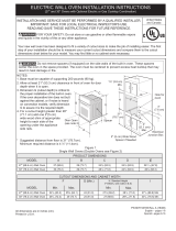
Figura 4 - CAJA DE EMPALMES
DE 3 ALAMBRES PUESTA A TIERRA
Cable desde el suministro de energía
Cable de la estufa
Alambre
desnudo
Alambre
rojos
Caja de
empalmes
Conductor de
unión listado-UL
(o CSA)
Alambre verde
o desnudo
Alambre
desnudo
Alambre
negros
(
Si su electrodoméstico está equipado
con un conductor neutro blanco.)
Este electrodoméstico está fabricado con un suministro
eléctrico neutro blanco y un alambre de cobre
conectado al armazón. El armazón esta puesto a tierra
por un enlace de la conexión a tierra con la conexión
del neutro al nal de la línea eléctrica, si es usado en
los estados unidos una nueva instalación de circuito
de bifurcación (1996 NEC), casa rodante, vehículos
recreacionales, o donde los códigos locales no permitan
poner a tierra mediante el neutro (blanco) o en Canadá,
desconectar la conexión blanca de la verde y utilizar
la conexión a tierra para poner a tierra la unidad de
acuerdo a los códigos locales, conectar el neutro al
circuito de bifurcación- conductor neutro de manera
usual. Ver Figura 5. Si su electrodoméstico va a ser
conectado a una caja de conexión puesta a tierra de
3 cables (en los estados unidos solamente), donde
los códigos locales permitan conectar el conductor de
poner a tierra-electrodoméstico con el neutro (blanco)
ver Figura 4.
NOTA AL ELECTRICISTA: Los conductores de cable
blindados provistos con este artefacto son aprobados
por UL para la conexión al alambrado de casa de un
calibre mayor. El aislamiento de los conductores está
calicado para temperaturas más altas que las del
alambrado de la casa. La capacidad de corriente del
conductor está gobernada por la calicación de la
temperatura del aislamiento alrededor del alambre en
vez de solamente el calibre del alambre.
Donde los códigos locales permitan conectar el
conductor de puesta a tierra del electrodoméstico al
neutral (blanco) (Solamente en los Estados Unidos)
(vea Figura 4):
1. Desconecte el suministro eléctrico.
2. En el caja de juntas: conectar el aparato y los
cables residenciales como se muestra en la
Figura 4.
16
INSTRUCCIONES DE INSTALACIÓN PARA EL HORNO ELÉCTRICO DE PARED
(con instrucciones para la instalación de la estufa)
Ubicación del número de modelo y de serie
La placa con el número de serie está ubicada en la
guarnición interior lateral del horno y se puede ver cuando
se abre la puerta.
Cuando haga pedidos de repuestos o solicite información
con respecto a su horno, esté siempre seguro de incluir el
número de modelo y de serie y el número o letra del lote
de la placa de serie de su horno.
Modelos con un solo horno-
la placa de serie está ubicada
aquí.
Modelos con un horno
doble- la placa de serie está
ubicada aquí.
Si el horno se usa en una instalación de circuito de
ramal nuevo (1996 NEC), en una casa rodante, en un
vehículo para recreación o si los códigos locales NO
permiten la conexión a tierra a través del cable neutral
(blanco), el armazón del electrodoméstico NO TIENE
QUE estar conectado al alambre neutro del sistema
eléctrico de 4 alambres. (ver Figura 5):
1. Desconecte el suministro eléctrico
2. Separe el alambre verde (o cobre desnudo) y el
alambre blanco del electrodoméstico.
3. En el caja de juntas: conectar el aparato y los cables
residenciales como se muestra en la Figura 5.
Figura 5- CAJA DE EMPALMES
DE 4 ALAMBRES PUESTA A TIERRA
Alambre
desnudo
Cable desde el suministro de energía
Alambre verde
o desnudo
Cable de la estufa
Caja de
empalmes
Conductor de
unión listado-UL
(o CSA)
Alambre
blanco
Alambre
rojos
Alambre
negros
Alambre blanco
Figure 6
17
INSTRUCCIONES DE INSTALACIÓN PARA EL HORNO ELÉCTRICO DE PARED
(con instrucciones para la instalación de la estufa)
IMPORTANTE
No levante o manipular el aparato por el asa de la
puerta o el panel de control.
3 Insertar el horno en la abertura del gabinete. Deslizar
el horno hacia dentro dejando 1½” (3,8 cm) de
espacio libre entre el horno y la parte delantera del
gabinete (ver la Figura 7).
4 Empujar el cable blindado a través del oricio del
gabinete y hacia la caja de paso mientras se desliza
el accesorio hacia adentro.
5 Empujar el horno hacia adentro y en contra del
gabinete
Peligro de Peso Pesado
Use 2 personas o más para mover e instalar el horno
de pared.
Si no cumple con esta instrucción, puede resultar en
lesiones personales o daños al horno de pared
1 Desembalar el horno de pared. Extraer la guarnición
inferior y los 2 tornillos unidos con cinta al panel
superior del horno.
2 Buscar los tornillos que se incluyen en el paquete de
literatura.
Figura 7
1 1/2" (3.8 cm)
distancia entre la
unidad y el gabinete
3. Instalación del Gabinete
6 Instalación de los tornillos de montado
El horno de pared puede inclinarse
cuando la puerta esta abierta. Los soportes de
montaje que vienen con el horno de pared deben
de estar ajustadas al armario y al aparato para
evitar que el horno de pared se incline y ocasione
quemaduras graves.
A. Los barrenos en las molduras laterales pueden
ser usadas como guía para localizar los tornillos de
montado de la unidad (Figura 8).
B. Use los dos tornillos proporcionados para colocar
la unidad en la cabina.
Tornillos de montado
Figura 8
Riesgo de volcamiento
• Un niño o adulto puede volcar el
horno y acabar muerto.
• Instale el dispositivo antivuelco
en el horno y/o en la estructura
según las instrucciones de
instalación.
Asegúrese de que el horno se vuelva a acoplar al
dispositivo antivuelco cuando lo mueva.
• No utilice el horno sin el dispositivo antivuelco
instalado y acoplado.
• Si no se siguen estas instrucciones, se puede
provocar la muerte o quemaduras graves en niños y
adultos.
Agujeros de instalación
del dispositivo
antivuelco
Consulte las instrucciones de
instalación proporcionadas
con su electrodoméstico para
instalarlo adecuadamente.
Verifique que la instalación se
haya realizado adecuada-
mente corroborando que los
tornillos antivuelco estén
colocados.
Pruebe la instalación ejercien-
do poca presión hacia abajo
sobre la puerta abierta del
horno. El horno no debe
inclinarse hacia adelante.
18
INSTRUCCIONES DE INSTALACIÓN PARA EL HORNO ELÉCTRICO DE PARED
(con instrucciones para la instalación de la estufa)
7 Instalación de la Guarnición Inferior:
La guarda de seguridad inferior
debe ser propiamente instalada para que el aparato
electrodoméstico funcióne correctamente. No operar
el horno sin la guarda de seguridad instalada. No usar
guardas fabricadas de madera o de algun otro material
que no sea el especicado. La guarda de seguridad
usada en esta unidad debe de corresponder a este
modelo. Si se operar el aparato electrodoméstico sin la
guarda de seguridad inferior correctamente instalada,
esto podria causar lesiones física, tambien puede
dañar el gabinete o puede causar daños el aparato
electrodoméstico.
Los tornillos para jar el borde inferior se suministran
con el horno. Los adornos son más fáciles de instalar
si se retira la puerta. Consulte el Manual de uso y
cuidado para obtener instrucciones sobre cómo retirar
la puerta del horno.
Todos los modelos de 30 ":
A. Coloque el desviador de aire (A) en su lugar como
se muestra en la Figura 9. Alinee las ubicaciones de
los tornillos y je ambos extremos.
B. Coloque el recorte de color combinado (B) en su
lugar como se muestra. Alinee las ubicaciones de los
tornillos y je ambos extremos.
A
B
A
B
Figura 9
19
INSTRUCCIONES DE INSTALACIÓN PARA EL HORNO ELÉCTRICO DE PARED
(con instrucciones para la instalación de la estufa)
G
F
H
36” Min.
(91.4cm) Min.
* Si no se instala ninguna tapa de cocina
directamente sobre la unidad del horno, se permite
un espacio máximo de 5" (12,7 cm) sobre el piso.
Figura 10: NSTALACIÓN TÍPICA DEBAJO DE LA MESADA DE HORNO SIMPLE EMPOTRADO
CON TAPA DE COCINA MONTADA
Approx. 3”
(7.5 cm)
4 1/2” (11.5 cm) Max.*
Instale contrachapado de 3/4" (1.9 cm)
sobre dos correderas, nivelado con la
parrilla inferior. La base debe poder
sostener 150 libras (68 kg) para los
modelos 27"y 200 libras (90 kg) para los
modelos 30".
Corte una abertura de 9" X 9"(23 cm X 23 cm)
(mínimo) en el fondo del contrachapado, a 2" (5
cm) del lado izquierdo del panel llenador, para
poder encaminar el cable a la caja de empalme.
208/240 caja de empalme
para hornos de pared
Los paneles de relleno laterales
del gabinete son necesarios para
aislar la unidad de los gabinetes
adyacentes. La altura del relleno
lateral del gabinete debe permi-
tir la instalación de modelos de
tapas de cocina aprobados.
Sólo ciertos modelos de tapas de cocina se pueden instalar
sobre ciertos modelos de hornos eléctricos empotrados. Las
tapas de cocina y los hornos empotrados se mencionan por su
número de identicación MFG ID y código de producto (ver la
planilla que se incluye en el paquete de literatura y las instruc-
ciones de instalación de la cocina donde están detalladas las
dimensiones). No instale una conguración lado a lado debajo
de los mostradores, o en combinación con una estufa.
Para reducir el riesgo
de lesiones personales
y inclinación del horno
de pared, éste debe
asegurarse a los
gabinetes mediante
soportes de montaje.
INSTALACIÓN TÍPICA DE BAJO CONTADOR
No quite los separadores de los muros laterales del horno empotrado. Estos espaciadores centran
el horno en el espacio provisto. El horno debe estar centrado para prevenir una concentración excesiva de calor
que podría resultar en daños por el calor o un incendio.
DIMENSIONES DE ABERTURA
F. ANCHURA G. PROFUNDIDAD H. ALTURA
30" (76.2 cm)
28
1
/
2
" (72.4 cm) Min.
29" (73.7 cm) Max.
24 (61.0)
27
1
/
4
(69.2) Min.
28
1
/
8
(71.4) Max.
20
INSTRUCCIONES DE INSTALACIÓN PARA EL HORNO ELÉCTRICO DE PARED
(con instrucciones para la instalación de la estufa)
5. Vericación del funcionamiento
Su modelo está equipado con un Control Electrónico de
Horno. Cada una de las funciones ha sido controlada en
fábrica antes del despacho. Sin embargo, le sugerimos
vericar el funcionamiento de los controles electrónicos
una vez más. Consulte la Guía de Uso y Cuidado o la
Guía del controles para ver el funcionamiento del horno.
1. Extraer todos los elementos de la parte interior del
horno.
2. Encender el horno (Consular la Guía de Uso y
Cuidado.)
3. Vericar el funcionamiento de los controles
electrónicos del horno:
Hornear Vericar que esta función caliente el horno.
Veinte minutos después de encender el horno, abrir la
puerta y ver si se siente que el calor emana desde su
interior.
Asar– Cuando se pone el horno para asar, el
elemento de arriba del horno debe de ponerse rojo.
Convección (algunos modelos) – Cuando se congura
el horno para horneado o asado por convección,
los dos elementos se encienden y apagan en forma
alterna y se enciende el ventilador. El ventilador de
convección dejará de funcionar cuando se abre la
puerta del horno durante el horneado o asado por
convección.
Antes de llamar al servicio
Lea la sección Lista de Control de Averías en su
Manual del Usuario. Esto le podrá ahorrar tiempo
y gastos. Esta lista incluye ocurrencias comunes
que no son el resultado de defectos de materiales o
fabricación de este artefacto.
Lea la garantía y la información sobre el servicio en
su Manual del Usuario para obtener el número de
teléfono gratuito.
IMPORTANTE
Un ventilador ubicado dentro de la parte trasera
superior arriba del horno (en algunos modelos)
permite la refrigeración de los componentes
eléctricos y electrónicos de enfriamiento.
Si el horno ha estado funcionando a altas
temperaturas, el ventilador seguirá funcionando
después de apagar el horno.
4. Asegúrese de que el horno de pared está a
nivel
1. Instale una rejilla al centro del horno superior (vea la
Figura 12).
2. Ponga un nivel por encima de la rejilla. Lea 2 veces,
una vez con el nivel a la posición de lado a lado, y otra
vez de atrás hacia adelante. Utilice trozo de madera
o cuñas por debajo del horno de pared para nivelar,
si sea necesario.
3. Vuelve a empezar
en el horno inferior.
Si el nivel muestra
que la rejilla no esta
a nivel, utilice trozo
de madera o cuñas
para componer
ambos hornos.
Figura 12
Figura 11 - INSTALACIÓN TÍPICA PARA UNA ESTUFA DE GAS ENCIMA
DE UN HORNO DE PARED INSTALADO DEBAJO DEL MOSTRADOR
18”(45.7 cm) Max.
6 1/2” Min.
(16.5 cm)
Adaptor
de gas
4”(10 cm)
Tomacorriente
puesto a tierra
de 120Voltios
/60Hz
Lado
derecho del
gabinete
(para tener
acceso a
la válvula
de cierre
manual)
Regulador
de presión
Válvula
de cierre
manual
Conector exible para artefactos
Lados del gabinete
o panel llenador
Gabinete del horno de pared
5” Max.
(12.7 cm)
Adaptor
de gas
ESTUFA DE GAS
  • Page 1 1
  • Page 2 2
  • Page 3 3
  • Page 4 4
  • Page 5 5
  • Page 6 6
  • Page 7 7
  • Page 8 8
  • Page 9 9
  • Page 10 10
  • Page 11 11
  • Page 12 12
  • Page 13 13
  • Page 14 14
  • Page 15 15
  • Page 16 16
  • Page 17 17
  • Page 18 18
  • Page 19 19
  • Page 20 20
  • Page 21 21
  • Page 22 22
  • Page 23 23
  • Page 24 24
  • Page 25 25
  • Page 26 26
  • Page 27 27
  • Page 28 28
  • Page 29 29
  • Page 30 30
  • Page 31 31
  • Page 32 32

Electrolux ECWD3011AS Installation guide

Category
Microwaves
Type
Installation guide
This manual is also suitable for

Ask a question and I''ll find the answer in the document

Finding information in a document is now easier with AI