Page is loading ...

owners
manual
MODEL NO.
113.24201
CAUTION:
Read SAFETY
iNSTRUCTIONS
carefully
CRRFr$1dgH
12-INCHBANDSAW/
SANDER
assembly
operating
repair parts
SEARS, ROEBUCK AND CO., Chicago, IL 60684 U.S.A. and SIMPSONS-SEARS LIMITED, Toronl
Part No. 69079 Printed In U,S.A.

general safety instructions for power roars
1, KNOW YOUR POWER TOOL
Read the owner's manual carefully. Learn =_s
application and limitations as well as the specific
potential hazards peculiar to this tool.
2. GROUND ALL TOOLS
This tool is equipped with an approved 3-conductor
cord and a 3-prong groundh=g type plug to fit the
proper grounding type receptacle. The green conductor
in the cord is the grounding wire. Never connect the
green wire to a live terminal.
3. KEEP GUARDS IN PLACE
and in working order.
4. REMOVE ADJUSTING KEYS
AND WRENCHES
Form habit of checking to see that keys and adjusting
wrenches are removed from tool before turning it on.
5. KEEP WORK AREA CLEAN
Cluttered areas and benches invite accidents. Floor
must not be slippery due to wax or sawdust.
6. AVOID DANGEROUS ENVIRONMENT
Don't use power tools in damp or wet locations. Keep
work area well lit. Provide adequate surrounding work
space.
7. KEEP CHILDREN AWAY
All visitors should be kept a safe distance from work
area.
8. MAKE WORKSHOP KID-PROOF
12. USE SAFETY GOGGLES
Safety goggles must comply with ANS Z87.1-1968.
Also use face or dust mask if cutting operation is
dusty.
13. SECURE WORK
Use clar_Ds or a vise to hold work when practical. It's
safer than using your hand, frees both hands to operate
tool.
14. DON'T OVERREACH
Keep proper footing and balance at all times.
15. MAINTAIN TOOLS WiTH CARE
Keep tools sharp and clean for best and safest
performance. Follow instructions for lubricating and
changing accessories.
16. DISCONNECT TOOLS
before servicing; when changing accessor=es such as
blades, bits, cutters, etc.
17. AVOID ACCIDENTAL STARTING
Make sure switch is in "OFF" position before plugging
in.
18.
USE RECOMMENDED ACCESSORIES
Consult the owner's manual for recommended
accessories. Follow the instructions that accompany
the accessories. The use of improper accessories may
cause hazards.
19. NEVER STAND ON TOOL
Serious =njury could occurif thetool istippedor if the
cutting tool is accidentally contacted.
with padlocks, master switches, or by removing
starter keys.
9. DON'T FORCE TOOL
It will do the iob better and safer at the rate for which
it was designed.
10. USE RIGHT TOOL
Don't force tool or attachment to do a job it was not
designed for.
11. WEAR PROPER APPAREL
No loose clothing, gloves, neckties or jewelry to get
caught in moving parts, Rubber-soled footwear is
recommended for best footing.
20.
Do not store materials above or near the tool suchthat
it isnecessary to stand on the tool to reach them.
CHECK DAMAGED PARTS
Before further use of the tool, a guard or other part that
is damaged should be carefully checked to ensure that it
will operate properly and perform its intended function
- check for alignment of moving parts, binding of
moving parts, breakage of parts, mounting, and any
other conditions that may affect its operation. A guard
or other part that is damaged should be properly
repaired or replaced.
THIS SAFETY SEAL OF THE
POWER TOOL INSTITUTE ASSURES YOU ...
I, Th=r the manufacturer's power tools, including fhe parllcular tool
associated with the Seal. are produced in acc0rdanc_ with applicable
Standards For Safer 3, of Underwriters" Laboratorles and American
National Standards (ANSI_.
2 That compliance with appilcable safety standards is assured by in-
dependent inspection and testing conducted by Underwriters' L=bara-
taries _UL).
3. That every moiarlzed too{ is inspected under power.
4. That ever), tool has with it adequate instructions and a llzt of safety
rules fc_r the protection of the user.
5, That the tool manufacturer _s a member of the Power Tool Institute and
;s a sponsor of the Insfitute's Consumer Safety Education Program.

Safety is a combination of operator common sense and
alertness at all times when the band saw is being used.
WARNING: FOR YOUR OWN SAFETY, DO NOT AT-
TEMPT TO OPERATE YOUR BAND SAW UNTIL IT IS
COMPLETELY ASSEMBLED AND INSTALLED ACCORD
ING TO THE INSTRUOTaONS . . . AND UNTIL YOU
HAVE READ AND UNDERSTAND THE FOLLOWBNG:
PAGE
1. General Safety Instructions for Power Tools ...... 2
2. Getting To Know Your Band Saw/Sander ....... 13
3. Basic Band Saw Operation .................. 15
4. Maintenance ........................... 19
5. Stability Of Machine
The band saw must be bolted securely to a stand or
work bench, in addition, if there is any tendency for the
band saw to tip over or move during certain operations
such as cutting long heavy boards. The band saw should
be bolted to the floor.
6. Location
The band saw should be positioned so neither the opera-
tor nor a casual observer is forced to stand in line with
the blade. This band saw is intended for indoor use only.
7. Protection: Eyes, Hands, Face, Ears, Body
a.
Wear safety goggles that comply with ANS Z87.1-
1968, and a face shield if operation is dusty. Wear
ear plugs or muffs during extended periods of opera-
tion. Do not wear gloves . . . roll long sleeves above
the elbow.
b. Do not cut pieces of material too small to hold by
hand.
d.
Avoid awkward hand positions, where a sudden slip
could cause a hand to mow into the blade or the
sanding belt.
Never turn your band saw "ON" before clearing the
table of a!l Objects (tools, scraps of wood, etc.)
except for the workpiece and related feed or support
devices for the operation planned.
e. Make sure the blade runs downward toward the table
in the right direction. Always adjust tracking wheels
correctly so that the blade does not run off the wheels.
f. Always adjust tension correctly for the blade or sand-
ing belt being used.
g. Always adjust the upper blade guides not more than
1/4" above your material when cutting.
h. When cutting a large piece of material, make sure it is
supported at table height.
i, Hold the work firmly against the table.
j. Do not feed the material too fast while cutting.
Only feed the material fa_t enough so that the blade
will cut. Keep fingers away from the blade.
k,
Use caution when cutting off material which is ir-
regular in cross section which could pinch the blade
before the cut is completed. A piece of molding for
example should lay flat on the table and no_ be per-
mitted to rock while being cut.
Use caution when cutting off round material such as
dowel rods, or tubing. They have a tendency to roll
while being cut causing the blade to "bite". Always
use a "V" block, or clamp round material to a miter
gauge.
m. When backing up the workpiece, the blade may bind
in the kerf (cut) . . . this is usually caused by sawdust
clogging up the kerf. If this happens;
I. Turn off the band saw, . . remove plug from power
source outlet . . . remove cover from band saw.
Insert a screwdriver or wedge in the kerf.., rotate
the wheels by hand while backing up the work-
piece.
n. Never leave the band saw work area with the power
on before the machine has come to a complete stop,
or without removing and storing the switch key.
o. Never operate the band saw with protective cover on
the unused shaft end of the motor removed.
8. If any part of this band saw should break, bend, or fail
in any way or any electrical component fail to perform
properly, or if any is missing, shut off power switch,
remove power supply cord from power supply and re-
place damaged missing and/or failed parts before re-
suming operation.
9. Read and follow the instructions appearing on front
of the band saw.
DANGER
FOR YOUR OWN SAFETY
1. READ AND UNDERSTAND OWNER'S MANUAL BE-
FORE OPERATING THIS MACHINE.
2. ALWAYS WEAR SAFETY GOGGLES WHEN OPER-
ATING THIS MACHINE.
3. BE POSITIVE THE SAW BLADE IS INSTALLED
PROPERLY TEETH POINTING DOWNWARD TO
WARD THE TABLE-BEFORE OPERATING MAC
HINE
4. BE SURE BLADE TENSION. BLADE GUIDES, AND
THRUST BEARINGS ARE PROPERLY ADJUSTED
BEFORE OPERATING MACHINE-SEE OWNERS MAN.
UAL.
5. ALWAYS ADJUST UPPER GUIDE TO CLEAR WORK-
PIECE BY NO MORE THEN 1/4 INCH.
6. MINIMIZE INJURY POTENTIAL OF CONTACTWITH
SAW BLADE OR SANDING BELT BY KEEPING
FINGERS A SAFE DISTANCE AWAY
7. MAINTAIN CONTROL OF THE WORKPIECE AT
ALL TIMES--HOLD FIRMLY AGAINST THE TABLE
8. BE ATTENTIVE TO THIN CUT-OFF PIECES HIT
TING END OF SLOT IN INSERT. OR JAMMING IN
SLOT.
10. Think Safety. Safety is a combination of operator com-
mon sense and alertness at all times the band saw/sander
is operating.

additiona! safety instructions
for band saw/sander
WARNING: THE 5" BAND SAW PULLEY AND THE
2-1/2" MOTOR PULLEY FURNISHED, WILL RUN THE
BLADE AT APPROXIMATELY 900 RPM (OR 2700
FEET PER MINUTEI WHEN USED WITH A 1725 RP_
MOTOR. NEVER SUBSTITUTE THESE PULLEYS TO
INCREASE THIS SPEED BECAUSE IT COULD BE DAN-
GEROUS.
WARNING: DO NOT ALLOW FAMILIARITY (GAINED
FROM FREQUENT USE OF YOUR BAND SAW) TO
BECOME COMMONPLACE. ALWAYS REMEMBER THAT
A CARELESS FRACTaON OF A SECOND IS SUFFI-
CIENT TO iNFLICT SEVERE iNJURY.
4

This machine is designed to use a 1725 RPM motor only.
Do not use any motor that runs faster than 1725 RPM.
It is wired for operation on 110-120 volts, 60 Hz., alter-
nating current. IT MUST NOT BE CONVERTED TO
OPERATE ON 230 VOI.TS. EVEN THOUGH SOME OF
THE RECOMMENDED MOTORS ARE DUAL VOLTAGE.
THESE CRAFTSMAN MOTORS HAVE BEEN
FOUND TO BE ACCEPTABLE FOR USE ON
THIS TOOL.
HP RPM VOLTS CATALOG NO.
1/3 1725 110-120 1250
1/2 1725 110-120 1254
1/2 1725 110-120 1255
CAUTION: Do not use blower or washing machine motors
or any motor with an automatic reset overload protector
as their use may be hazardous.
CONNECTING TO POWER SOURCE OUTLET
This machine must be grounded while in use to protect
the operator from electric shock,
Plug power cord into a 110-120V properly grounded type
outlet protected by a 15-amp. time delay or Circuit-Saver
fuse or circuit breaker.
If you are not sure that your outlet is properly grounded,
have it checked by a qualified electrician.
WARNING: DO NOT PERMIT FINGERS TO TOUCH THE
TERMINALS OF PLUGS WHEN INSTALLING OR RE-
MOVING THE PLUG TO OR FROM THE OUTLET.
WARNING: IF NOT PROPERLY GROUNDED THIS
POWER TOOL CAN INCUR THE POTENTIAL HAZARD
OF ELECTRICAL SHOCK. PARTICULARLY WHEN USED
IN DAMP LOCATIONS IN PROXIMITY TO PLUMBING.
IF AN ELECTRICAL SHOCK OCCURS THERE IS THE
POTENTIAL OF A SECONDARY HAZARD SUCH AS
YOUR HANDS CONTACTING THE SAW BLADE.
If power cord is worn or cut, or damaged in any way, have
it replaced immediately.
If your unit is for use on less than 150 volts it has a plug
that looks like below.
PROPERLY
GROUNDED
OUTLET_,_
/fl UI
/n ul
3--PRONG
PLUG
<
GROUNDING
PRONG
This power tool is equipped with a 3-conductor cord and
grounding type plug which has a grounding prong, approved
by Underwriters' Laboratories and the Canadian Standards
Association. The ground conductor has a green jacket and
is attached to the tool housing at one end and to the ground
prong in the attachment plug at the other end.
This plug requires a mating 3-conductor grounded type
outlet as shown.
If the outlet you are planning to use for this power tool is
of the two prong type DO NOT REMOVE OR ALTER
THE GROUNDING PRONG IN ANY MANNER. Use an
adapter as shown and always connect the grounding lug to
known ground.
It is recommended that you have a qualified electrician
replace the TWO prong outlet with a properly grounded
THREE prong outlet.
An adapter as shown below is available for connecting plugs
to 2-prong receptacles. The green grounding lug extending
from the adapter must be connected to a permanent ground
such as to a properly grounded outlet box.
NOTE: The adapter illustrated is for use only if you already
have a properly grounded 2-prong receptacle. Adapter is
not allowed in Canada by the Canadian Electrical Code.
The use of any extension cord will cause some toss of
power. To keep this to a minimum and to prevent over-
heating and motor burn-out, use the table below to deter-
mine the minimum wire size (A.W,G.) extension cord. Use
only 3 wire extension cords which have 3-prong grounding
type plugs and 3-pate receptacles which accept the tools
plug.
Extension Cord Length Wire Size A.W.G.
Up to 100 Ft. 16
100-200 Ft. 14
200-400 Ft, 10
CHECK MOTOR ROTATION
WARNING: FOR YOUR OWN SAFETY, MAKE SURE
PLUG IS NOT CONNECTED TO POWER SOURCE OUT-
LET. WHEN CHANGING MOTOR ROTATION.
The motor must rotate COUNTERCLOCKWISE when
viewed from the shaft end to which you will mount the
pulley. (See page 11) If it does not, change the direction
according to the instructions furnished with the motor.

unpacking and checking contents
CONTENTS
UNPACKING AND CHECKING CONTENTS ..... 6
ASSEMBLY ........................... 7
Mounting Band Saw/Sander on Recommended
Craftsman Floor Base ................... 7
Installing Sawdust Elbow ................. 8
Installing Table ....................... 9
Motor Pulley Belt Guard and Motor Installation.. 10
Check Motor Rotation .................. 11
Mounting Motor ...................... 12
Attaching Belt Guards ................... 13
Installing The Blade .................... 15
Adjusting The Table .................... 19
On-Off Switch ........................ 20
GETTING TO KNOW YOUR BAND
SAW/SANDER ......................... 22
Adjustment Diagrams ................... 22
Tension Adjustment Knob ................ 22
Tension Scales ........................ 22
Table Tilting ......................... 22
Blade Guide Adjustment ................. 22
Lateral Guide Adjustment ................ 22
Blade Thrust Bearing Adjustment ........... 22
Guide Bar Lock Knob .................. 22
Guide Bar ........................... 23
Installing Sanding Attachment ............. 23
BASIC BAND SAW/SANDER OPERATION ...... 25
Sawing ............................. 25
Sanding ............................ 25
MAINTENANCE ........................ 26
Tires .............................. 26
General ........................... 26
Motor ............................. 26
Lubrication .......................... 26
TROUBLE SHOOTING ................... 27
Recommended Accessories................ 27
REPAIR PARTS ........................ 28
- TOOLS NEEDED -- - -
MEDIUM SCREWDRIVER 3!8-tNCH WRENCH
1
\
I
7
8 /
Your Band Saw/Sander s shipped comolete m one carton
(w_thout rno[or or floor basel
Separate all oarts from packing materials and check each
i[ern w_th Ilustratlon and "Table of Loose Parts." Make
certain all items are accounted for before discarding any
paekinq material.
Key TABLE OF LOOSE PARTS Qty.
N0.
1 Bas_e Saw Assembly ................ 1
2 Owner's Manual. 1
3 Saw Table ...................... , 1
4 1/2x 52-1n, V-Belt .................. , 1
5 Carton containing Belt Guard, Belt-Guard Support,
6 Support Bracket, three Clips and three Self-
Tapping Screws ................... 2
1
8
9
I/2-I n. Sanding Belt I
I/4-I n. Band-Saw Blade ............... I
Sawdust E I bow 1
Two Bags containing the following ttems:
Set Screw Wrench, 1/8" . ............ 1
Set Bcrew Wrench, 5/32" . ........... 1
Set Screw Wrench, 3/16" . ........... t
Flat Washer, 1 I/8" diameter ........... 2
Trunmon Locknut ................. I
Pan-Hd. Mach, Screw, Self Tap, 10-32x3i8", . . . 2
Pan Rd. aaeh, Screw, Self Tap, B-32x1/4" . . . . 1
Soc-Hd. Setscrew, Flat Pt,, 5/16-t8x3/8" . .... 1
Flat Hd. Mach_ Screw, 6-32x7/16". ........ 1
Hex Nut, 6-32 .................... 1
Spht Lockwasher, No. 6 .............. 1
Tilt Pointer ..................... 1
Knurled Hd. Mach. Screw .............. 1
Tube Clamp ..................... I
Rubber Gasket (str,ps) .............. I
A ignmen t Plate ................... I
Motor Pulley, 2-I/2". ............... I
Sanding Platen .................. I
Table Inaetl {nartowalot, for sawing) ....... 1
Table Insert (w_de slot, for sanding) ........ 1
Tilt Lock Handle (Wrench) 1
Spacer 1
Blade Tenspon Knob ................ !
Switch Key .................... 2

assemb!y
MOUNTING BAND SAW/SANDER ON RECOMMENDED
CRAFTSMAN FLOOR BASE
1. Unscrew the four knobs on the front of the band saw
and remove the cover.
NOTE: Check the bolts which hold the feet to the band
saw. Make sure they are tight . , . they may have come
loose during shipment.
2. Place the band saw on the base, position as shown, and
align mounting holes.
3. Find one 5/16"-18 x 3" Hex. Head bolt, two 5/16"-
18 x 2" Hex. Head bolt, three nuts, flat washers and
Iockwashers furnished with base. Find one 1-1/8'" dia.
flat washer from among the loose parts furnished.
4. Position the stiffner furnished with base as shown.
5. Insert the two 2" bolts through the holes in the right
foot and through the holes in the stiffner.
6. Place a flat washer, Iockwasher, and a nut on these
bolts from underneath. Do not tighten the nuts.
LEFT
FOOT_
CHECK BOLTS
FOR
STIFFNER
7. Place the 1-1/8" diameter flat washer on the 3"
bolt and insert the bolt in the hole in the left foot.
Place a flat washer, a Iockwasher, and a nut on the bolt
from underneath and tighten the nut. Now tighten the
other two nuts which you installed before.
8. Find two Hex. Head screws 7/16" long, and two nuts
furnished with base, Insert these screws thru the top
of the base and stiffner and screw on the nuts. Tighten
the nuts.
3" BOLT
I
F LATWASH ER -.-------_ @
LOCKWASHER
NUT b
7

assembly
INSTALLING SAWDUST ELBOW
1. Find the sawdust elbow, the clamp, the strip of rubber
gasket, and two 10-32 x 3/8" self-threading screws
among the loose parts.
SELF-THREADING
SCREW
The holes for attaching the clamp are not threaded, but
the screws are "self-threading" and will cut a thread as
they are screwed in.
2. Screw both of the self-threading screws into the holes to
cut the threads and then remove them.
3. Place the elbow in the opening, and attach the clamp
with the two screws.
CLAMP
/
SAWDUST ELBOW
RUBBER GASKET
4. Peel off the protective covering from the rubber gasket
and stick it around the clamp. Make sure it extends
a little beyond each end of the clamp.
The gasket will help to prevent sawdust from leaking
out.
For the most efficient removal of sawdust, attach a
Craftsman Home-n-Shop Vac to the sawdust elbow.
\
\
8

TABLE TRUNNION
INSTALLING TABLE
Remove the protective oil that is applied to the table.
Use any ordinary household type grease and spot remover.
CAUTION: Never use gasoline, naptha or similar highly
volatile solvents.
Apply a coat of automobile wax to the table.
\
\
NION PiN
TABLE LOCK BOLT
1. Place the table on the band saw so that the two trunnion
pins and the table lock bolt go through the slot in the
trunnion.
2. Find the 1-I/8" dia. flat washer, a sleeve 11/16" long,
the trunnion lock nut and the table lock handle from
among the loose parts,
3, Hold the head of the table lock bolt inside the band saw
with your left hand and put the 1-1/8" dia. flat washer,
the sleeve, and the handle on the bolt.
4. Screw the nut on the bolt and tighten it with the handle
while the table is in a horizontal position.
_NUT
lllJ,;/
TABLE LOCK BOLT TABLE LOCK HANDLE

assemb|y
MOTOR PULLEY BELT GUARD AND MOTOR
INSTA L LAT! ON
MOUNTING BELT GUARD
1. Place the motor on your workbench with the shaft
facing you.
If you are using a double shaft motor, the 5/8" dia.
shaft must be facing you.
BELT GUARD
SU PPORT BRACKET
THREAD CUTTING
SCREWS
BELT GUARD
SUPPORT
2. Attach guard support to the bracket with the two
screws, furnished with the guard.
NOTE: The holes in the bracket arenot threaded, but the
screws are "thread cutting screws" and will cut a thread as
they are tightened.
SCREWS
10

MOUNTING PULLEY
I. Loosen setscrew in motor pulley and place the pulley on
the shaft with the hub flush with the end of the shaft,
insert the motor shaft key and tighten setscrew with
5/32" setscrew wrench.
When installing the pulley on a 1/2" diameter motor
shaft, make sure that the adapter sleeve and 3/16"
square key furnished with your motor are in place.
Then tighten the setscrew with a 5/32" setscrew wrench.
s/32 iNCH I _ /
SETSCREW
WRENC.
_J___'_"_ MOTOR
_- FLUSH HERE SHAFT
KEY
3/16x 3/16 KEY ....,.
L
\
ADAPTER SLEEVE
112" DIAo MOTOR SHAFT
CHECK MOTOR ROTATION
The motor must rotate COUNTERCLOCKWISE when
viewed from the PULLEY end.
I. Place the motor on your workbench or on the floor.
2. Stand clear of the motor and plug the cord into a pro-
perly grounded outlet (See page 4). Notice the rotation
of the pulley. If it is not turning COUNTERCLOCK-
WISE, REMOVE the plug from the outlet, and change
the rotation of the motor according to the instructions
furnished with the motor.
WARNING: FOR YOUR OWN SAFETY, MAKE SURE
PLUG IS NOT CONNECTED TO POWER SOURCE OUT-
LET WHEN CHANGING MOTOR ROTATION.
11

assembly
MOUNTING MOTOR
1. Find four 5/16"-18x 1" carriage bolts, flat washers,lock-
washersand nuts supplied with base.
2, Insert bolts through holes marked "X" from behind
motor mount bracket.
3. Attach motor.., place a flat washer and a Iockwasher
on each holt . . . screw on nuts but DON'T TIGHTEN
them.
4. Loosen the two BELT GUARD SUPPORT SCREWS.
5. Loosen the two MOTOR BASE CLAMP SCREWS and
rotate the motor so that the ventilation holes are
facing downward ... tighten the screws.
6. Tighten the BELT GUARD SUPPORT SCREWS.
MOTOR MOUNT
BRACKET -[ : c:_ L--J_ _-_c:_
BELT GUARD
SUPPORT SCREWS _,_
VENTILATION HOLES
FACING DOWNWARD
MOTOR BASE
CLAMP SC
(BOTH ENDS)
12

ATTACHING BELT GUARDS
1. Remove the pulley from the band saw, using the 5/32"
setscrew wrench to loosen the screw. Be careful not to
lose the shaft key.
Attach the belt guard support with the three screws fur-
nished with the guard.
NOTE: The support bracket is not required.
The holes for attaching the support are not threaded,
but the screws are "self-threading" and will cut a
thread as they are screwed in.
SELF-THREADING SCREW
2. Replace the pulley with the hub flush with the end of
the shaft.
FLUSH HERE
/
13

assembty
LONG TAB
POINTED THIS WAY
\
3. Install three clips on the belt guard 90 ° apart with the
long tabs pointing AWAY from the round opening.
4. Insert one looped end of belt all the way into guard so
that it will be below motor pulley.
OPEN END
/
/
_'_--SPRING CLIPS
_"_ (SET 90 ° APART)
5. Snap the guard into position as shown,
14

6. Look down into guard.., pull belt upwards onto motor
pulley.
7. Insert the belt into the open end of the second belt
guard, and out the round opening, Place belt onto the
band saw pulley by rotating pulley.
8. Snap the belt guard into position,
9. Move the motor sideways so that the belt is in the cen-
ter of the opening in the top of the base.
10, PUSH downward on motor to apply tension to belt
and tighten motor bolt nuts.
NOTE: It is only necessary to tension the belt so that it
does not slip while running.
If you cannot obtain sufficient tension with the motor
pushed all the way down, remove the four motor bolts
and insert them in the LOWE R set of holes.
BLADE TENSION
KNOB
iNSTALLING THE BLADE
1. Find the blade tension knob among the loose parts. Put
a dab of grease or vaseline on the end of the knob and
screw it on the tension stud. Screw it on only a few
turns, just enough to start moving the pointer.
2. Loosen the two mounting screws and remove the blade
guard.
.TENSION
STUD
POINTER
-,-BLADE GUARD
MOUNTING
15

assembly
3. Loosen the guide bar lock knob and position the upper
guide assembly approximately three inches above the
table and tighten the knob,
GUIDE BAR LOCK KNOB
GUIDE BAR
UPPER BLADE ..__ !
4. Loosen the two setscrews which lock the upper blade
guidesand separate them about 1/8".
Do that same thing to the lower guides beneath the
table,
UPPER THRUST BEARING
1/8" SETSCREW
WR ENCH''_ !
SETSCR EWS
BLADE GUIDE
16

UPPER THRUST BEARING
5. Loosen the setscrew which locks the upper thrust bear-
ing and turn knob until the thrust bearing is all the way
back.
THRUST BEARING
ADJ. KNOB
1/8" SETSCREW WRENCH
/
BLADE GUIDE
6. Loosen the setscrew which locks the lower thrust bear-
ing and turn the knob until the thrust bearing is all the
way back.
LOWER THRUST BEARING
SETSCREW
)
17

assembly
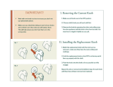
7. Carefully uncoil the blade, holding it at arms length.
8. Place the blade over the wheels with the teeth pointing
downwards. Make sure the blade is between the blade
guides and is in the center of the rubber tires.
9. Screw down the tension knob until the pointer points
to 1/4. This will put sufficient tension on the blade
which is 114" wide.
10. Turn the upper wheel by hand a few times and notice
if the blade remains in the approx, center of the tire on
the top wheel.
If the blade moves away from the center of the wheel
while you are turning it. the blade is not TRACKING
properly.
The top wheel shaft is hinged which allows the wheel
to be tilted so that the blade can be TRACKED. By
turning the tracking adjustment screw, the wheel will
be tilted.
If the blade moves toward the front of the band saw:
a. Turn the tracking adjustment screw clockwise about
1/4 of a turn, as though you were tightening it.
If the blade moves toward the back of the band saw:
a. Turn the tracking adjustment screw counterclock-
wise about 1/4 of a turn as though you were loosen-
mg it.
Turn the screw just enough to cause the blade to run in
the approximate center of the tire,
TRACKING
ADJUSTMENT
SCREW
BLADE
CENTERED
ON TIRES
OF BOTH
WHEELS
The thrust bearings support the blade from the rear and
will rotate when the blade is pushed against them while
you are cutting. As soon as you stop cutting, the bear-
ings should step rotating.
11. Turn the thrust bearing adjustment knob so that the
thrust bearing moves toward the blade and almost
touches it.
12. Turn the upper wheel by hand so that the blade moves
downward, move the bearing until it barely touches the
blade and starts to rotate. Now move the bearing back
slightly, until it stops rotating. Tighten the thrust
bearing setscrew.
13, Adjust the lower thrust bearing the same way.
THRUST BEARIN(
r
THRUST BEARING
ADJ. KNOB
18

14. Loosen the setscrew which locks the blade guide holder.
15. Turn the blade guide adjustment knob, so that the guides
move toward the blade. Move them until the "ledge" is
about 1/32" from the deepest part of the blade teeth.
This deep part is called a "gullet". Tighten the setscrew.
16. Adjust the lower guides the same way.
GL
APPROX.
1/32"'
BLADE GUIDE
KNOB
SETSCREW
BLADE GUIDE HOLDER
17. Press the two guides evenly against the sides of the blade,
but don't pinch the blade. Release the guides and rotate
the upper wheel a little bit, moving the blade downward.
Make sure one guide is not farther away from the blade
than the other. Tighten both setscrews_
18. Adjust the lower guides the same way.
19, Rotate the upper wheel a few times by hand, and check
the guides and thrust bearings. Make readjustments if
necessary.
20. Replace the blade guard on the upper guides.
21. Locate the table insert with the narrow slot and place it
in the opening in the table.
22. Replace the cover.
Y liII
*'-"-- SAW BLADE
_UPPER BLADE GUIDE
_'_TABLE ALIGNMENT
SCREW
ADJUSTING THE TABLE
1. Locate among the loose parts a 5/16"-18" x 3/8"
socket head flat point setscrew and a knurled head
screw. The knurled head screw keeps the table in align-
ment. Screw it into the tapped hole underneath the
front edge of the table.
2. The socket head screw acts as a 90 ° stop. Screw it
partially into the tapped hole in the top of the table
on the left side. Use the 5/32" setscrew wrench.
3. Raise the blade guides all the way up.
4. Loosen the table lock slightly and push down on the
left side of the table until it touches the frame of the
band saw.
5. Screw in the stop screw and notice that as it touches the
frame, the table will start to tilt.
6. Place a square on the table against the blade and con-
tinue to screw in the stop screw until the table is square
with the blade. Tighten the table lock.
7. Find the pointer and a pan head screw 8-32 x I/4 inches
long and attach the pointer. Set at 0 degrees and tighten
the screw.
COMBiNATiON SQUARE
19
DE
5/32"' SETSCREW WRENCH

assembly
ON-OFF SW|TCH
WARNING: DON'T CONNECT POWER CORD
TO ELECTRICAL OUTLET IN YOUR SHOP
UNTIL YOU ARE SURE THAT MOTOR ROTATION
IS CORRECT. (SEEPAGE 11).
The On-Off Switch hasa locking feature.TH|S SHOULD
PREVENT UNAUTHORIZED AN DPOSSIBLY HAZAR-
DOUS USE BY CHILDREN AND OTHERS.
1. Insert key into switch.
NOTE: Key ismade of yellow plastic
©
2. To turn machine on, insert finger under switch lever
and pull end of switch out.
2O
/