Page is loading ...

8_6
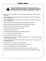
OWNERS
MANUAL
Model No.
486.24311
CAUTION'.
Read Rules for
Safe Operation
and Instructions
Carefully
\
\
CRRFTSI4RN
TINE DE-THATCHER
(For 42" Lawnsweepers)
• Safety
• Assembly
• Operation
• Maintenance
• Parts
Sears, Roebuck and Co., Hoffman Estates, IL. 60179 U.S.A.
F_RfNTED IN U,S,A.

Safety Rules .......................................................... 2
Warranty ................................................................ 2
Full Size Hardware Chart .................................... 3
Assembly ............................................................... 4
Operation ............................................................... 8
Malr_tenance .......................................................... 8
Storage ................................................................... 8
Troubleshooting .................................................... 8
Repair Parts Illustration ........................................ 9
Repair Parts List ............................................. _,..10
Parts Ordering/Service ...,.................. Back Cover
Any power equipment can cause injury if operated improperty or if the user does not understand how to
operate the equipment. Exercise caution at all times when using power equipment.
• Read this owners manual carefully for operating and
service instructions before attempting to assemble or
operate the de-thatcher. Be thoroughly familiar with
the proper use of the de-thatcher.
• Read the vehicle owners manual and vehicle safety
rules, and know how to operate the vehicle before
using the de-thatcher.
• Read the lawnsweeper owners manual and safety
rules, and know how to operate the lawnsweeper
before using the de-thatcher.
• Never allow children to operate the tractor or de-
thatcher attachment, and do not allow adults to
operate without proper instructions.
• This de-thatcher attachment has sharp tine points.
Always handle with care and wear substantialfoot
wear when operating this de-thatcher.
• Do not allow anyone to ride or sit on de-thatcher, the
lawnsweeper or on the towing vehicle.
• Keep the area of operation clear of all persons,
particularly small children, and also pets.
• Always begin with the transmission in first (low) gear
and engine at low speed, and gradually increase
speed as conditions permit,
= The vehicle braking and stability may be affected
with the attachment of this equipment. Be aware of
changing conditions on slopes. Refer to safety rules
in the vehicle owner's manual concerning safe
operation on slopes. STAY OFF OF STEEP
SLOPES.
• Always operate up and down a slop_, never across
the face of a slope
• This equipment shouldbe operated at reduced
speed on rough terrain, along creeks and ditches
and on hillsides, to prevent tipping and loss of
control. Do not drive too close to a creek or a ditch.
o Do not tow this equipment on a highway or any other
public thoroughfare.
• Follow the maintenance instructions as outlined in
this owners manual,
1
LOOK FOR THIS SYMBOL TO POINT OUT IMPORTANT SAFETY PRECAUTIONS. I
IT MEANS--ATTENTION!! BECOME ALERTI! YOUR SAFETY IS INVOLVED. J•
LIMITED ONE YEAR WARRANTY ON TINE DETHATCHER
For one year from the date of purchase, when this tine dethatcher is maintained and lubricated according to
the operating and maintenance instructions in the owner's manual, Sears wiit repair any defect in material or
workmanship free of charge. If this tine dethatcher is used for commercial or rental purposes, this warranty
applies for only 90 days from the date of purchase.
This warranty does not cover repairs necessary because of operator negligence or abuse, including the failure
to maintain the equipment according to instructions contained in the owner's manual.
WARRANTY SERVICE iS AVAILABLE BY CONTACTING THE NEAREST SEARS SERVICE CENTER/
DEPARTMENT IN THE UNITED STATES.
This warranty applies only while this product is in the United States.
This warranty gives you specific legat rights, and you may also have other rights which vary from state to ststel
Sears, Roebuck and Co. D/817 WA. Hoffman Estates, Chicago, IL 60179

M
N
_fG
(NOT SHOWN ACTU/_L SIZE)
Key Qty, Description Key Qty. Descrlption
,., ...... i
A
B
C
D
E
F
G
H
1
2
12
2
13
23
3
2
1
2
Hex Bolt, 5/16-18 x 3-1/4" Lg.
Hex Bolt, 5/16-18 x 3/4" Lg.
Carriage Bolt, 5/16-18 x t" Lg.
Carriage Bolt, 5/16-18 x 3/4" Lg.
J
K
L
M
I
23
t5
1
Flat Washer, 5/16" Std, Wrt.
Lock Washer, 5/16"
Tooth Lock Washer
Hairpin Cotter, 3/32"
Hex Nut, 5/16"
Hex Lock Nut, 5/16"
Palnut, 1/4"
Palnut, 3/8"
Ftat Washer, 1-1/2" O.D.
N
O
P
Q
R
t
1
1
3
2
Knob
Grip, Height Adjustment Handte
Grip, Height Adjustment Strap
Angle Bracket
Hitch Arm Mount Bracket

CARTONCONTENTS(LooseParts{nCarton) 5, ChannelHitchBracket
1, TineShield 6. HeightAdjustmentLever
2. SpringTines(12) 7, HeightAdjustmentHandle
3. HitchMountBars(2) 8, PivotRod
4, HitchMountArms(2) 9. SpringAlignmentRod
Y
\
TOOLS REQUIRED FOR ASSEMBLY
(2) 1/2"Wrenches "
(1) Hammer
Before assembling the de-thatcher, lay out all of the
parts and hardware as shown on the previous pages,
ASSEMBLY OF DETHATCHER
* Assemble six spring tines to the front of the tine
shield using six 5/I6" x 3/4" carriage bolts, tooth tock
washers, 5/16" lock washers and 5/16" hex nuts.
Tighten. See figure 1,
NOTE: Tines must be seated between dimples and
against front edge of tine shield,
TOOTH LOCK WAS_
SPRING
/
5/16" x 3/4"
CARRIAGE BOLT
TINE SHIELD (FRONT)
FIGURE 1
Place one end of the spring alignment rod against a
hard surface and use a hammer to tap a 1/4" palnut
onto the rod. Assemble a t-!/2" flat washer, six
spring tines (all facing the same direction), and
another 1-t/2" flat washer onto the rod. Finatly, tap
another 1/4" palnut onto the other end of the rod.
See figure 2.
NOTE: The spring alignment rod prevents rear spring
tines from pivotingand becoming loose.
1-1/2" FLAT WASHER
SPRING TINE
PALNUT
PALNUT
IGMENT ROD
1-1/2" FLAT WASH ER
FIGURE 2

Assembte the spring tines with rod to the rear of the
tine shield using six 5/16" x 3/4" carriage bolts, tooth
lock washers, 5/16" lock washers and 5/t 6" hex
nuts. Ttghten, See figure 3.
NOTE: Tines must be seated between dimples.
5/16" HEX NUT'---_
5/16" LOCK WASHER _
TOOTH LOCK WASHER _'
SPRING TINE
t
5/16" x 3/4"
\ CARRIAGE BOLT
TINE SHIELD (FRONT)
FIGURE 3
Assemble the three angle brackets to the top of the
tine shield as shown in figure 4, using a 5/i6" x 3/4"
hex bolt, a 5/16" lock washer and a 5/16" hex nut for
each bracket.
NOTE: The slotted holes in the tine shield allow for
adjustment when mounting the de-thatcher to the
lawnsweeper.
5/16" x 3/4" SLOTrED
HEX BOLT HOLE
ANGLE
BRACKET._.=
HOLE
Assemble the hftch arm mount brackets to the top
of the tine shield using a 5/16" x 3/4" hex bolt, a
5/16" lock washer and a 5/16" hex nut for each
bracket. See figure 5.
5/16" x 3/4"
HEX
HITCH ARM
MNT. BRKT. "_
FIGURE 5
Assemble the hitch mount bars to the outside of the
angle brackets using two 5/16" x 3/4" he× bolts and
two 5/16" hex lock nuts. Fasten through the slotted
holes in the bars, Tighten so that the bars can pivot.
See figure 6.
Assemble the hitch mount bars to the hitch arm
mount brackets using two 5/16"x 1" carriage bolts,
tooth lock washers, 5/16" lock washers and 5/16"
hex nuts. (Be sure to place the tooth lock washer
between the hitch mount bar and the hitch arm
mount bracket.) See figure 6.
HITCH MOUNT BAR
ANGLE BRACKET
5/16" x 3/4"
HEX BOLT
5/16" HEX
LOCK NUT
5/16" LOCK
WASHER
5/16" HEX NUT
;" xl"
CARRIAGE BOLT
HITCH ARM
MNT. BRKT.
TOOTH LOCK WASHER
FIGURE 4
FIGURE 6

Assemble the plastic grip onto the height adjustment
lever, See figure 7.
Assemble the height adjustment lever to the middle
angle bracket using a 5/16" x 3/4" hex bolt and a
5/16" hex lock nut, Tighten so that the lever can
pivot. See figure 7.
HEIGHT
ADJUSTMENT
LEVER _. GRIP
5/16" x 3/4" \_ ' ._
BOLT 5116" LO.CKo UT
FIGURE 7
Assemble the hitch mount arms to the channel hitch
bracket using four 5/16" x 3/4" hex bolts, 5/16" lock
washers and 5/16" hex nuts. See figure 5.
5/16" X 3/4"
HITCH MOUNT ARM _ HE)( BOLT
5/16" LOCKWASHER _ '_
CHANNEL HITCH __ _F_
5/16" HEX NUT
i
FIGURE 8
Remove the bolts, lock washers and hex nuts which
fasten the ends of the sweeper hitch tubes together.
Assemble the channel hitch bracket to the hitch
tubes, using two new 5/16" x 3-t/4" hex bolts and re-
using the original 5/16" lock washers and 5/I6" hex
nuts. See figure 9.
5/16" HE)( NUT
(ORIGINAL)
5/16" LOCK
WASHER
7
5/16" x 3-1/4"
HEX BOLT
FIGURE 9
Remove the height adjustment handle from the
sweeper, keeping all of the hardware for use with the
new handle.
Assemble the new height adjustment handte to the
sweeper, re-using the original 5/16" x 1-5/8" curved
head bolts, bowed washers, 5/16" lock washers and
5/16" hex nuts as shown in figure 10.
Assemble the plastic grip onto the new height
adjustment handle. See figure 10.
HEIGHT ADJUSTMENT
HANDLE
5/16" X 1-5/8"
CURVED HEAD
BOLT (ORIGINAL)
BOWED WASHER
HEX NUT
FIGURE 10
5/16" LOCK WASHER
(ORIGINAL)

Fasten the sweeper height adjustment strap to the
new height adjustment handle, re-using the original
5/16" x 3/4" carriage bolt, tooth lock washer, 5/16"
flat washer and knob. Place the tooth lock washer
between the handle and the strap, See figure 1t.
HEIGHT ADJUSTMENT
HANDLE (NEW),_._
SWEEPER HEIGHT
ADJUSTMENT STRAP N
5/16" x 3/4"
CARRIAGE BOLT _ q
(ORIGINAL)
KNOB
(ORIGINAL)
5/16" FLAT
-_WASHER
)RIGINAL)
TOOTH
_LOCK
WASHER
(ORIGINA_
HITCH
MOUNT
BAR
ROD
3/8"PALNUT
FIGURE 12
HITCH
MOUNT
ARM
3/32"
HAIRPIN
FIGURE 11
To assemble the 3/8" palnut onto the pivot rod, place
the end of the rod with the cross hole against a hard
surface. Using a hammer, tap the palnut onto the
solid end of the pivot rod.
Place the de-thatcher underneath the hitch tubes in
front of the sweeper. Connect the hitch mount bars
to the hitch mount arms using the pivot rod and the
3/32" hairpin cotter as shown in figure 12.
NOTE: If the hitch mount bars do not line up as shown
with the hitch mount arms, the angle brackets at the
rear of the tine shield may be loosened and moved
side to side, This wilt adjust the bars to align on the
outside of the arms.
,,ll
Fasten the de-thatcher height adjustment lever to the
sweeper height adjustment strap using a 5/16" x 3/4"
carriage bolt, a tooth lock washer, a 5/16" fiat washer
and a knob. Place the tooth lock washer between the
strap and the lever. See figure 13.
s/is"x3/4"
CARRIAGE BOLT
5/16" FLAT
WASHER
\
FIGURE 13

KNOW YOUR DETHATCHER
HOW TO USE YOUR DETHATCHER
HEIGHT ADJUSTMENT
HANDLE (SWEEPER)
HEIGHT ADJUSTMENT
LEVER (DETHATCHER)
KNOB (HEIGHT
ADJUSTMENT)
HITCH ARM
MOUNT BRACKET
TINE SHIELD
Height Adjustment Handle (Sweeper)
Adjusts the height of the sweeper and aiso affects
the height of the dethatcher.
Height Adjustment Lever (Dethatcher)
Raises and lowers the height of the dethatcher
independently of the sweeper.
Knob (Height Adjustment)
Loosens to unlock the height adjustment lever for
changing the height setting of the dethatcher.
Hitch Arm Mount Bracket
Adjusts to level the dethatcher from side to side and
front to back,
TIne Shield
Supports the spring tines to allow flipping action.
RAISING/LOWERING THE DE-THATCHER
To independently raise or lower the de-thatcher,
simply loosen the height adjustment knob which
locks the de-thatcher height adjustment lever in
place. Using the lever, lower the de-thatcher to the
operating position or raise itto the transport position
and then retighten the knob.
SETTING THE OPERATING POSITION
There are adjustment slots to help achieve proper height
and leveling of the de-thatcher during sweeping. Proper
adjustment of the tine shield and spring tines is
important for effective performance.
* Drive the towing vehicle and Eawnsweeper/de-
thatcher onto smooth, tevel ground or paved
surface.
Set the sweeper to the desired operating height.
(The best height is usually with the brushes set
aboL_t1/2" down intothe grass.) Refer to your
sweeper owner's manual for sweeper hook up and
operating instructions.
• Loosen the height adjustment knob and lower the
de-thatcher so that the spring tines rest on the
ground.
Adjust the tine shield so that it is level with the
surface by loosening the carriage bolts in the hitch
arm mount brackets. Both the front and rear tines
should contact the ground.
Retighten the carriage bolts in the hitch arm mount
brackets. The de-thatcher will maintain it's adjust-
ment for that particular sweeper height setting.
Retighten the knob to lock the de-thatcher in either
the operating or transport position.

USING THE DE-THATCHER
Regular removal of thatch is critical to the maintenance
of a healthy lawn. Thatch is layer of stems, clippings,
runners, roots and leaves that have not decayed• Exces-
sive thatch prevents air, water and fertilizer from reach-
ing the roots• The de-thatcher wilt effectively dislodge
excessive thatch from your lawn.
Start with the tractor in low gear. Vary the forward
speed to determine the best speed for maximum de-
thatcher performance.
Use a crisscross pattern to achieve the most even
removal of thatch.
o. On slopes, always operate in an up and down
direction only.
o Avoid extremely sharp turns.
Depending on conditions, it may be necessary to make
adjustments to the original height and level settings of
the de-thatcher.
o If thatch is not being adequately removed, lower the
height setting of the de-thatcher till the tines come
more forcefully in contact with the ground.
• If the tines are digging excessively into the soil, raise
the height setting of the de-thatcher.
• If the front tines pull back and don't achieve a flippin£
action, slightly raise the front end of the de.thatcher.
CUSTOMER RESPONSIBILITIES
• Read and follow the maintenance schedule and the maintenance procedures listed in this section.
MAINTENANCE SCHEDULE
Fill in dates as you
complete regular service.
Checkfor loosefasteners
Checkfor worn or damagedparts ....
Cleaning
LubricatePivotPoints
X
X X
X X
X
ServiceDates
..u,
i i, ii ii ll,,,
• Before each use check all nuts and bolts for tight-
ness.
• If rust appears on the shield or spring tines, sand
lightly and coat with enamel paint.
e Clean after each use to help prevent rust. • Always store in a dry area, and coat exposed metal
with light oil when not in use.
PROBLEM CAUSE CORRECTION
Tines not removing thatch Dethatcher set too high Lower dethatcher closer to ground
Tines digging excessively into soil Dethatcher set too low Raise dethatcher
Tines bend under, don't flip thatch Dethatcher set too low Raise dethatcher
forward Dethatcher angled down in front Raise front end slightly

19
13 18 /
--8
/
16 2 12
20 27
\ /
18
19
13
/
2O 6
15
19
1!3

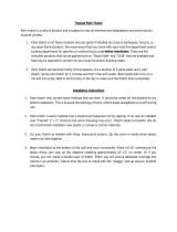
REPAIR PARTS FORTINE DE-THATCHER MODEL NO. 486.24311
REF, PART QTY, DESCRIPTION
NO. NO.
i , i,.i
1 24171
2 24172
3 24173
4 46761
5 24217
6 46762
7 24219
8 24174
9 ,24175
10 23442
11 23869
12 46766
13 43182
14 43080
15 44732
1 Tine Shield
2 Hitch Mount Arm
1 Channel Hitch Bracket
12 Spring Tine
REF. PART QTY.
NO. NO.
16 44917 1
17 43055 1
18 43086 23
19 43083 23
DESCRIPTION
Palnut, 3/8"
Hairpin Cotter, 3/32" #3
Lock WaSher, 5/16"
Hex Nut, 5/16-18 Thread
1 Height Adjustment Lever
1 Spring Alignment Rod
1 Pivot Rod
2 Hitch Mount Bar
1 Height Adjustment Handle
2 Hitch Arm Mount Bracket
3 Angle Bracket
2 Hex Bolt, 5/16-18 x 3-1/4" Lg.
12 Hex Bolt, 5/16-18 x 3/4" Lg.
13 Carriage Bolt, 6/16-18 x 3/4" Lg.
15 Tooth Lock Washer, 5/16" I.D.
20 43572
21 43943
22 43064
23 44326
24 46831
25 43081
26 43720
27 726-0106
47306
,
1
3
2
1
1
1
2
1
Flat Washer, 1-1/2" O.D. x
11/32" I.D,
Grip
Hex Lock Nut, 5/t6-18 Thread
Carriage Bolt, 5/16-18 x 1" Lg.
Grip
Flat Washer, 5/16" Std. Wrt.
Knob, Wing
Palnut, 1/4"
Owner's Manual
Purchase Common Hardware Locally
11
/