Page is loading ...

Item No. 2350057-1 en Rev 05/14
Installation Instructions
Blade Replacement and Adjustment for the
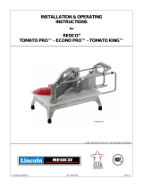
Tomato Pro
TM
, Econo Pro
TM
and Tomato King
TM
To ensure safe installation and operation, read the following statements
and understand their meaning. Please read carefully.
WARNING
Warning is used to indicate the presence of a hazard that can cause
severe personal injury, death, or substantial property damage if the
warning is ignored.
Replacing Blade assemBly
WARNING
Sharp Blade Hazard.
Blades are sharp and can cause cuts and
amputation.
To avoid injury from sharp blades, handle with caution. Only trained
personal should operate equipment or preform maintenance.
We suggest you change the complete assembly. Never mix old and new blades in
the same assembly as this may lead to excessive blade breakage.
Wash new blades with warm, soapy water and rinse thoroughly to remove the thin
protective oil lm. Keep the sharp edge away from you when handling blades.
1. Allow yourself ample room to work on a at, dry surface. Familiarize yourself
with the parts diagram for your equipment. Blade assemblies consist of blades,
blade blocks, blade block pins, rubber seals, and screws.
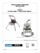
2. When changing blade assemblies on the Tomato King, close the pusher head
so that the pusher head ngers are through the blades resting against the pin
stop.
3. When changing blade assemblies on the Tomato Pro and Econo Pro
equipment, pull the pusher head assembly back away from the blades so it is
against the back stop.
4. To remove blade assemblies, use the proper tool to remove the four blade
block screws (2 at each end). Retain the rubber seals that are mounted on the
screws between the blade blocks and the casting.
5. Dispose of used blades and blade assemblies properly.
adjustments
1. Examine the pusher head ngers. If they are nicked or burred, smooth the
rough edges with a small at le. The spaces between the ngers must be
uniform. Straighten any bent ngers.
2. Center the new blade assembly between bridge casting posts with the sharp
side facing the pusher head. Replace screws and rubber seals. Be certain that
the bottom blade ts between the two bottom-most pusher head ngers.
3. Check the clearance between the pusher head ngers and blades. Make sure
they do not rest on or touch the blades at any point when you move the head
through its full travel. If there is contact, adjustments must be made. Pusher
head ngers must never contact blades.
To adjust Pusher Head Fingers between blades:
1. Carefully insert a screwdriver (B) between the slots in the Pusher Head
Assembly (A). Gently tap on the screwdriver (B) (up or down) to alter the
location of the Pusher Head Fingers so the slide effortlessly through the blades.
See Figure 1.
B
A
Figure 1. Pusher Head Adjustment Between the Blades.
2. It may also be necessary to adjust the Pusher Head Assembly (A) from the
back side of the equipment, as well. If needed, carefully insert a screwdriver (B)
between the slots in the Pusher Head Assembly. Gently tap on the screwdriver
(B) (up or down) to alter the location of the Pusher Head Fingers so they slide
effortlessly through the blades. See Figure 2.
A
B
Figure 2. Pusher Head Adjustment Between the Blades.

www.vollrath.com
The Vollrath Company, L.L.C.
1236 North 18th Street
Sheboygan, WI 53081-3201
U.S.A.
Main Tel: 800.628.0830
Fax: 800.752.5620
Technical Services: 800.628.0832
Service Fax: 920.459.5462
Canada Service: 800.695.8560
© 2014 The Vollrath Company, L.L.C.
Adjust the Pusher Head Assembly through the Blades:
1. Momentarily loosen set screws to the guide rods to adjust the location of the
Pusher Head Assembly by pushing / pulling on the guide rod. Once the Pusher
Head Assembly is properly located, tighten the set screws. See Figure 3.
Figure 3. Pusher Head Adjustment Through the Blades.
Tightening the blades:
Blades must be tightened in alternating sequence
1. Keep blade assembly centered between casting end-posts with a gap of air
space between the blade block and post.
2. Tighten screws one-half turn at a time in the following order:
A. Top Right - 1/2 Turn
B. Bottom Left - 1/2 Turn
C. Bottom Right - 1/2 Turn
D. Top Left - 1/2 Turn
3. Repeat this sequence until the screws are tight. Check for proper blade
tightness by strumming the dull side of the blade to identify a uniform vibration.
/


