Page is loading ...

iOptron
®
iEQ30 Pro
TM
Equatorial Mount
Instruction Manual
Product #3000E
®

2
This product is a precision instrument. Please read the included QSG before assembling the
mount. Please read the entire Instruction Manual before operating the mount.
If you have any questions please contact us at support@ioptron.com
WARNING!
NEVER USE A TELESCOPE TO LOOK AT THE SUN WITHOUT A PROPER FILTER!
Looking at or near the Sun will cause instant and irreversible damage to your eye.
Children should always have adult supervision while observing.

3
Table of Content
Table of Content ......................................................................................................................................... 3
1. iEQ30 Pro
TM
German Equatorial Mount Overview ................................................................................ 5
2. iEQ30 Pro
TM
Mount Assembly ............................................................................................................... 6
2.1. Parts List .......................................................................................................................................... 6
2.2. Identification of Parts ....................................................................................................................... 7
2.3. iEQ30 Pro Mount Ports .................................................................................................................... 8
2.4. Go2Nova
®
8407+ Hand Controller .................................................................................................. 9
2.4.1. Key Description ........................................................................................................................ 9
2.4.2. The LCD Screen ..................................................................................................................... 10
3. iEQ30 Pro
TM
Mount Assembly ............................................................................................................. 12
3.1. Introduction .................................................................................................................................... 12
3.2. iEQ30 Pro Mount Assembly .......................................................................................................... 13
3.2.1. STEP 1. Setup Tripod ............................................................................................................. 13
3.2.2. STEP 2. Attaching the Mount ................................................................................................. 13
3.2.3. STEP 3. Setting the Latitude ................................................................................................... 13
3.2.4. STEP 4. Installing the Counterweight (CW) Shaft ................................................................. 14
3.2.5. STEP 5. Installing Counterweight(s) ...................................................................................... 14
3.2.6. STEP 6. Balancing the Payload .............................................................................................. 15
3.2.7. STEP 7. Connecting Cables .................................................................................................... 16
3.2.8. STEP 8. Setting Controller ..................................................................................................... 16
3.2.9. STEP 9. Polar Alignment ........................................................................................................ 18
3.2.10. STEP 10. Returning the Mount to Zero Position .................................................................. 20
4. Getting Started ...................................................................................................................................... 21
4.1. Setup the Mount and Polar Alignment........................................................................................... 21
4.2. Manual Operation of the Mount .................................................................................................... 21
4.3. One Star Alignment ....................................................................................................................... 21
4.4. GOTO the Moon and Other Objects .............................................................................................. 21
4.5. Star Identifying Function ............................................................................................................... 22
4.6. Turn Off the Mount ........................................................................................................................ 22
4.7. Packing the Mount for Transportation ........................................................................................... 22
5. Complete Functions of Go2Nova
®
Hand Controller ............................................................................ 23
5.1. Slew to an Object ........................................................................................................................... 23
5.1.1. Solar System ........................................................................................................................... 23
5.1.2. Deep Sky Objects .................................................................................................................... 23
5.1.3. Stars: ....................................................................................................................................... 23
5.1.4. Comets .................................................................................................................................... 23
5.1.5. Asteroids ................................................................................................................................. 23
5.1.6. Constellations .......................................................................................................................... 23
5.1.7. Custom Objects ....................................................................................................................... 24
5.1.8. Custom R.A. DEC................................................................................................................... 24
5.2. Sync to Target ................................................................................................................................ 24
5.3. Alignment ...................................................................................................................................... 24
5.3.1. Pole Star Position .................................................................................................................... 24
5.3.2. One Star Alignment ................................................................................................................ 24
5.3.3. Two Star Polar Align .............................................................................................................. 24
5.3.4. Three Star Align ...................................................................................................................... 25
5.3.5. Solar System Align ................................................................................................................. 25
5.3.6. Polar Iterate Align ................................................................................................................... 25

4
5.3.7. View Model Error ................................................................................................................... 25
5.3.8. Clear Alignment Data ............................................................................................................. 25
5.4. Settings ........................................................................................................................................... 26
5.4.1. Set Time and Site .................................................................................................................... 26
5.4.2. Set Beep .................................................................................................................................. 26
5.4.3. Set Display .............................................................................................................................. 26
5.4.4. Set Guiding Rate ..................................................................................................................... 26
5.4.5. Set Tracking Rate .................................................................................................................... 27
5.4.6. Set Parking Position ................................................................................................................ 27
5.4.7. Meridian Treatment ................................................................................................................ 27
5.4.8. Track Below Horizon .............................................................................................................. 27
5.4.9. Set Eyepiece Light .................................................................................................................. 27
5.4.10. HBX Heating OFF/ON ......................................................................................................... 27
5.4.11. Language ............................................................................................................................... 28
5.5. Electric Focuser ............................................................................................................................. 28
5.6. PEC Option .................................................................................................................................... 28
5.6.1. Record PEC ............................................................................................................................. 28
5.6.2. PEC Data Integrity .................................................................................................................. 28
5.7. Park Telescope ............................................................................................................................... 28
5.8. Edit User Objects ........................................................................................................................... 29
5.8.1. Enter a New Comet ................................................................................................................. 29
5.8.2. Enter Other Objects or Observation List ................................................................................ 29
5.9. Firmware Information .................................................................................................................... 30
5.10. Zero Position ................................................................................................................................ 30
5.10.1. Goto Zero Position ................................................................................................................ 30
5.10.2. Set Zero Position ................................................................................................................... 30
6. Maintenance and Servicing ................................................................................................................... 31
6.1. Maintenance ................................................................................................................................... 31
6.2. iOptron Customer Service .............................................................................................................. 31
6.3. Product End of Life Disposal Instructions ..................................................................................... 31
6.4. Battery Replacement and Disposal Instructions ............................................................................ 31
Appendix A. Technical Specifications ..................................................................................................... 32
Appendix B. iEQ30 Pro Go2Nova
®
8407+ HC MENU STRUCTURE ................................................... 33
Appendix C. Firmware Upgrade ............................................................................................................... 36
Appendix D. Computer Control an iEQ30 Pro Mount ............................................................................. 37
Appendix E. Go2Nova
®
Star List ............................................................................................................. 38
IOPTRON TWO YEAR TELESCOPE, MOUNT, AND CONTROLLER WARRANTY .................... 45
Rev. 1.0 2015.04
iOptron reserves the rights to revise this instruction without notice. Actual color/contents/design may differ from those described in this
instruction.

5
1. iEQ30 Pro
TM
German Equatorial Mount Overview
The iEQ30 Pro
TM
GOTO German equatorial mount is one of the next generation premium astro-
imaging mounts from iOptron. Based on the success of iEQ30 mount, the iEQ30 Pro mount uses high
resolution, low noise stepper motor to offer better GOTO and tracking accuracy. The mount is made of
the highest quality materials to ensure stability and durability. With a payload of 30 lb (13.5 kg)
balanced – it comes standard with a calibrated dark field illumination polar scope and a sturdy 1.5-inch
stainless steel tripod. Its lighter weight (only 15 lb or 6.8 kg) makes it much easier to carry.
Features:
Specialized astrophotography mount ideal for entry-level and intermediate astrophotographers
Portable, compact, and sturdy German equatorial mount with the highest Payload/Mount ratio
(>2.0) in the category
Payload: 30 lb (13.5 kg) (excluding counterweight)
Mount weight: 15 lb (6.8 kg)
Ultra-accurate tracking with temperature-compensated crystal oscillator (TCXO)
FlexiTouch
TM
Gap-free structure for both R.A. and DEC worm gears
Resolution: 0.14 arc second
Go2Nova
®
8407+ controller with Advanced GOTONOVA
®
GoTo Technology
Permanent periodic error correction (PPEC)
Built-in 32-channel Global Positioning System (GPS)
Integrated ST-4 compatible autoguiding port
AccuAlign
TM
G2 polar scope with dark-field illumination and Quick Polar Alignment procedure,
allowing fast and accurate polar alignment
BrightStar Polar Alignment routine for those who can’t see the Pole Star
iOptron port for electronic focuser, laser pointer, planetary dome control
RS232 port for computer control via ASCOM platform
Heated hand controller for low temperature operation (as low as -20ºC)
3.5 inch V-type saddle
Standard 1.5 inch heavy-duty stainless steel tripod (4.8kg), optional 2 inch tripod (8kg)
Optional hard case (#3080)
Optional StarFi wireless adapter (#8434)
Optional USB to RS232 Converter with FTDI chipset (#8435)
Optional 42-inch (#8033) or 48-inch (#8030) pier
Optional Tri-pier (#8034)
Optional PowerWeight
TM
rechargeable battery pack (#8128)
Optional 2kg (4.5lbs) counterweight (#3006-05, beige)

6
2. iEQ30 Pro
TM
Mount Assembly
2.1. Parts List
1
There are two shipping boxes for an iEQ30 Pro mount (#3000E). One box contains an EQ
mount, with counterweight shaft and Polar scope, and an 8407+ hand controller. One box for 1.5” tripod,
one 5kg counterweight and accessories. The contents are:
iOptron iEQ30 Pro telescope mount (#3200E) or iEQ30 Pro telescope mount with hard case
(#3200E-HC) with hand controller
Tripod (#3021)
o One 5lb counterweight
o 6P6C RJ11 (6 pin connector, straight wired) coiled controller cables X2
o Illuminating LED with cable
o AC adapter (100V~240V)
o 12V DC adapter cable with car lighter plug
o 4P4C RJ9 (4 pin connector) to DB9 RS232 serial cable for firmware upgrade and
computer control.
o Azimuth locking screws X2
o Low latitude adjustment knob
o CW extension shaft
Quick Start Guide
OPTIONAL PARTS
42 inch pier (#8033) /48 inch pier (#8030)
Tri-Pier (#8034)
Counterweight extension shaft (#7126)
Carrying case (#3080)
StarFi wireless adapter (#8434)
USB to RS232 Converter with FTDI chipset (#8435)
PowerWeight
TM
rechargeable counterweight battery (#8128)
ONLINE RESOURCES (click on the “Support” menu at www.iOptron.com)
Quick Start Guide
This instruction manual
Tips for set up
Hand controller and mount firmware upgrades (check online for latest version)
ASCOM driver
Reviews and feedback from other customers
Accessories
1
US market only. Actual contents may vary.

7
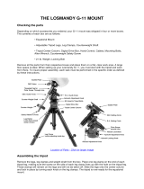
2.2. Identification of Parts
Lat. Adj. Knob & Lever
DEC Clutch
Dovetail Saddle
Dovetail Lock Screw
R.A. Unit
Polar Scope Cover
Lat. Locking Screw (4)
Azi. Adj. Knob
Azi. Locking Screw (2)
DEC Unit
Polar Axis Cover
DEC Axis
CW Shaft
CW Locking Screw
CW Shaft Extension
CW Safety Screw
Counterweight (CW)
R.A. Axis
Alignment Peg
Tripod Leg
Tripod Support
Tripod Head
Tripod Lock
Leg Locking Lever
Figure 1. iEQ30 Pro mount assembly

8
2.3. iEQ30 Pro Mount Ports
Ports on Main Control Unit
Figure 2. Ports on main control unit
Dec: For connecting to DEC driver unit
Port: Auxiliary port for connecting to other iOptron accessories, such as an electronic
focuser or for observatory dome control. DO NOT plug your ST-4 guiding camera cable into
this port as it may damage the mount or guide camera electronics.
HBX (Hand Box): For connecting to an 8407+ Hand Controller
Reticle: Power supply for the polar scope illuminated reticle LED, or illuminated eyepiece
POWER: power indicator
I/O: Power switch
DC12V: DC power socket to power the mount (2.1mmX5.5mm, center positive)
Guide: ST-4 compatible autoguiding port
RS232: Serial port (4P4C RJ9 connector) for mount-computer control and firmware upgrade
Figure 3. Guide port and RS232 (serial) port pin-out assignment
Port on DEC Unit
The only port on the DEC unit is used to connect to the Dec port on main control unit.
Figure 4. Port on DEC unit

9
2.4. Go2Nova
®
8407+ Hand Controller
Figure 5. Go2Nova
®
8407+ hand controller
The Go2Nova
®
8407+ hand controller (HC) shown in Figure 5 is the standard controllers that
used for the iEQ30 Pro mount. It has an integrated temperature controller that ensures it can be
operated as low as -20ºC (-4ºF). It has a large LCD screen, function, direction and number keys on the
front; a red LED reading light on the back; and a HBX port (6-pin) and a serial port (4-pin) at the bottom.
2.4.1. Key Description
MENU Key: Press “MENU” to enter the Main Menu.
BACK Key: Move back to the previous screen, or end/cancel current operation, such as
slewing.
ENTER Key: Confirm an input, go to the next menu, select a choice, or slew the telescope to
a selected object.
Arrow (▲▼◄►) Keys: The arrow keys are used to control the movement of DEC and R.A.
axes. Press and hold ▲(DEC+),▼(DEC-) buttons to move a telescope along the DEC
direction, ◄(R.A.+), ►(R.A.-) to move a telescope along the RA direction. They are also used
to browse the menu or move the cursor while in the menu. Press and holding an arrow key for
a fast scrolling.
Number Keys: Input numerical values. Also used to adjust speeds (1: 1X; 2: 2X; 3: 8X; 4:
16X; 5: 64X; 6: 128X; 7: 256X; 8: 512X; 9: MAX)
Light Key(☼): Turns on/off the red LED reading light on the back of the controller.
Help (?) Key: Identify and display bright stars or objects where the telescope points to.
STOP/0 Key: Stop the mount during GOTO. Also toggling between start and stop tracking.
HBX (Handbox) port: connect the HC to the iEQ30 Pro mount using a 6P6C RJ11 cable.
HBX
Port
Serial
Port
RA+
RA-
DEC-
DEC+

10
Serial port (i.e., RS232 port): connect the HC to a Computer for HC firmware upgrade via a
RS232-RJ9 cable. The pin out of the serial port is shown in Figure 6.
Figure 6. Serial port pin out on an 8407 hand controller
2.4.2. The LCD Screen
The 8407+ HC has a large 8-line, 21-character per line LCD screen, which displays all the
information as shown in Figure 7. The user interface is simple and easy to operate.
Figure 7. 8407+ HC LCD Information Screen
1. Target Name/Mount Position: displays the name of the target that telescope is currently pointed to
or the current mount position.
Zero Position: The reference position for the mount. It will be displayed when moved to Zero
Position using “Goto Zero Position”;
User Position: The mount is point to a user defined position, which could be a particular
celestial object or simply a position determined by pressing an arrow key;
An object name, such as “Mercury” or “Andromeda Galaxy”: Name of the star or celestial
object that the mount is currently slewing to or tracking.
2. Target R.A.: Right Ascension (R.A.) of the target object.
3. Target Declination: Declination (DEC) of the target object.
4. Right Ascension: Current R.A. of the telescope.
5. Declination: Current DEC of the telescope.
6. Altitude: Altitude of the telescope (degrees vertical from the local horizon - zenith is 90º).
7. Azimuth: Azimuth of the telescope (north is 0º, east 90º, south 180º, and west 270º).
8. Local Date and Time: display local time in a format of YY-MM-DD HH:MM:SS.

11
9. Mount Status: Display current operation status of the mount.
Stop: mount is not moving;
Slew: mount is moving with an arrow key is pressed or a GOTO command, such as “Select
and Slew” or “Goto Zero Position”;
Tracking: mount is at a tracking status.
10. GPS status: When the power is turned on, the initial GPS status will be “GPS ON”, which means
that the mount is connected to its GPS receiver and is seeking a satellite signal. When the GPS
receiver finds the satellites and receives the GPS signal, the status will change to “GPS OK”.
11. PEC status: Display of “PEC” here Indicates the Periodic Error Correction playback is turned on.
12. Tracking speed: Display current tracking rates of the mount
SDRL: mount is tracking at a sidereal speed;
Solar: mount is tracking at a solar speed;
Lunar: mount is tracking at a lunar speed;
King: mount is tracking at a King speed;
CSTM: mount us tracking at a customer defined speed.
13. Slew speed: It has 9 speeds: 1X, 2X, 8X, 16X, 64X, 128X, 256X, 512X, MAX (1400X,~5.8º/sec).
14. Operation Mode: EQ indicates that the mount is operating in an equatorial mode.

12
3. iEQ30 Pro
TM
Mount Assembly
3.1. Introduction
Congratulations! You have just purchased a new design of telescope mount that has a class
leading payload capacity for its weight and is capable of high precision tracking. This makes the iEQ30
Pro a superb choice for observational astronomy and astrophotography as part of a portable setup for
use in your backyard, at dark sky sites, and at star parties.
In order for you to get the optimum performance from the mount and your optical tube assembly
(OTA) combination, you must assemble and set up the mount correctly.
The following basic principles are included to help you understand the fundamental concepts of
telescope mounts before the specific details of the iEQ30 Pro mount are covered.
Telescope mounts are either equatorial or altitude-azimuth (Alt-Az). Both types of mount rotate
the OTA around two perpendicular axes to point to a desired object in the night sky.
An Alt-Az is a simple mount that has a horizontal axis to provide vertical (altitude) OTA
movement from the local horizon and a vertical axis to provide horizontal (azimuth) OTA movement and
is therefore able to point at any part of the sky. In order to track an object across the sky, an Alt-Az
mount has to continually move the OTA in both axes. This can provide tracking that is good enough for
visual observing and short exposure photography. However, the mechanics of this system are such
that an OTA carried by an Alt-Az mount will suffer from field rotation where stars will appear to rotate
about the point being tracked forming arcs. As such Alt-Az mounts are not suitable for long exposure
astrophotography which is needed to capture faint deep sky objects.
An equatorial mount has an axis, called the right ascension (R.A.) axis, aligned with the celestial
North Pole (CNP) in northern latitudes, or the celestial South Pole (CSP) in the Southern Hemisphere.
Equatorial mounts counteract the rotation of the Earth by driving the R.A. axis in the opposite direction
thus tracking celestial objects as they appear to move across the sky. Once the mount has been
accurately aligned to the celestial pole, only movement of the R.A. axis is required for accurate tracking
and this design does not suffer from field rotation .R.A. is the celestial equivalent of longitude and is the
angular distance measured eastward along the celestial equator as measured from a zero reference
point (the vernal equinox). A second axis perpendicular to the R.A., the declination axis (DEC),
provides elevation relative to the celestial equator.
As mentioned above, in order to track celestial objects the R.A. axis of an equatorial mount
must be accurately aligned with the celestial pole. Your new iOptron mount comes equipped with
features that make accurate alignment quick and easy. The iEQ30 Pro includes mechanical adjusters
that move the mount in altitude and azimuth in order to align the R.A. axis, also known as the mount’s
Polar Axis, with the celestial pole. These adjustments do not involve any rotation of the mount’s R.A. or
DEC axes and can be performed without the OTA installed. The first step is to make an approximate
azimuth alignment of the mount’s Polar Axis by roughly aligning the R.A. axis to a reference point
toward True North (or True South if in the Southern Hemisphere). A compass can be used for this initial
azimuth alignment but you must allow for the variation between True and Magnetic North/South at your
location. Precise horizontal alignment of the Polar Axis is accomplished with the azimuth adjustment
bolts on the mount. The second step is to adjust the Polar Axis vertically (altitude) above the horizon by
setting the observer’s latitude on the provided latitude scale. This procedure is based on the
fundamental geometry of the Earth’s coordinate system in conjunction with the concept of the celestial
sphere. You can verify this by visualizing yourself at the North Pole (latitude N90°) in which case
Polaris will be 90° from the horizon, or directly overhead. These steps will place the Polar Axis very
close to the celestial pole. The accuracy of both of the above adjustments can be enhanced by the use
of the incorporated polar scope, which sits in an opening along the R.A. axis and allows direct viewing
of the pole. In order to get the most out of your equatorial mount it is essential to understand the
concept of polar alignment and how the equatorial mount helps you establish and maintain a true Polar
Axis alignment. Now you are ready to set up the GOTO functionality of the iEQ30 Pro mount – which

13
gives access to more than 300,000 celestial objects – by performing star alignments using the
equatorial mount’s electronic controller, and enjoy the night sky.
The iEQ30 Pro mount is a next-generation equatorial mount that provides the precision
alignment capabilities required for today’s complete astronomy solution. The following sections of this
manual provide the detailed steps required to successfully set up and operate the iEQ30 Pro mount.
3.2. iEQ30 Pro Mount Assembly
NOTE: The iEQ30 Pro is a precision astronomical instrument. It is highly recommended that you
read the entire manual and become familiar with the nomenclature and function of all
components before starting the assembly.
3.2.1. STEP 1. Setup Tripod
Expand the tripod legs and install the Tripod Spreader
using the Tripod Lock as shown in Figure 8. Tightening the
Tripod Lock will expand the tripod legs fully and provide
maximum support for the mount and the Optical Tube
Assembly (OTA). Adjust the tripod. It is recommended that
you extend the legs fully during the first assembly and modify
the length as required in subsequent adjustments. After the
legs are adjusted and locked, stand the tripod with the
Alignment Peg facing True North. If you are located in the
southern hemisphere, face the Alignment Peg True South.
CAUTION: If the latitude of your location is below 20º,
you may move the Alignment Peg to the opposite
position to prevent the counterweights from hitting the
tripod legs.
3.2.2. STEP 2. Attaching the Mount
Tighten the R.A. Clutch. Carefully remove the mount from the shipping box. Familiarize yourself
with the components shown in Figure 1.
BubbleLevel
Az.LockingScrew
Az.Adjust.Knob
Figure 9
AlignmentPeg
Figure 10
Back out the Azimuth Adjustment Knobs (next to the Bubble Level Indicator) to prevent blocking
the Alignment Peg (Figure 9). Put the mount onto the tripod head (or pier top) with bubble level on top
of the Alignment Peg (Figure 10). Secure the mount head by tightening Azimuth Locking Screws. Level
the mount by adjusting individual tripod leg (or pier foot). You may use the build-in Bubble Level
Indicator or an external level to check leveling.
3.2.3. STEP 3. Setting the Latitude
Unlock the R.A. Clutch and rotate the mount 180º around the R.A. axis (Figure 11) to move the
dovetail face upside. Tighten the R.A. Clutch. Unscrew the Latitude Adjustment Lever from Latitude
Adjustment Knob (Figure 12). Turn the Latitude Adjustment Knob to set your current latitude, which is
displayed in La. Mark Window. Use the Lever for fine adjustments as needed. You may set the latitude
without the load for an easy adjustment.
Alignment Peg
TripodLock
TripodTray
Figure 8 Tripod

14
DovetailSaddle
R.A.Clutch
R.A.axis
PolarAxis
Figure 11
Lat.Adjust.Lever
Lat.Adjust.Knob
HighLat.Position
LowLat.Position
Lat.MarkWindow
Figure 12
The iEQ30 Pro mount has two latitude setting positions: a High Latitude Position (25º ~ 65º) and
a Low Latitude Position (0º ~ 35º). It can be set by change the Position Safety Pin. If the latitude of your
location is between 25º and 65º, set the Position Safety Pin at High Latitude Position and choose a long
Latitude Adjust Knob for high latitude. If the observation latitude is between 0º and 35º, set the Position
Safety Pin at Low Latitude Position and choose a short Latitude Adjust Knob for low latitude. The
factory set default position is High Latitude Position.
CAUTION: If your location latitude requires changing the Latitude Adjustment Knob, change the
knob before attaching the mount to the tripod.
3.2.4. STEP 4. Installing the Counterweight (CW) Shaft
Unscrew the CW shaft from the top of the mount as shown in Figure 13(a) and thread it into the
opening of the DEC axis as shown in Figure 13(b).
(a) (b)
Figure 13. Install counterweight shaft
3.2.5. STEP 5. Installing Counterweight(s)
iEQ30 Pro mount comes with a 10lb (4.5kg) counterweight (CW). Use CW or CW and extension
bar to balance your OTA. Additional CW can be ordered from iOptron for those the payload (payload
torque, more precisely) exceeds the equipped CW.
Before installing the counterweight, make sure that both R.A. and DEC clutches are fully
engaged to avoid sudden mount movements which could cause injury and/or damage the mount gear
system and your equipment.

15
Make sure the mount is at the zero position (i.e. counterweight shaft is pointing to the ground)
when installing the counterweight.
Release the R.A. Clutch to set the R.A. axis free before loading the CW. Remove the CW
Safety Screw on the end of the CW shaft. Guide the CW over the shaft and tighten the CW Locking
Screw to hold the CW in place. Always place the Safety Screw back onto the shaft prior to use to
prevent personal injury and/or equipment damage. Lock four R.A. Clutch Screws again.
WARNING: The mount should always be kept in the zero position while it is being loaded
with CWs and payload.
WARNING: The zero position is the only safe position the mount should stay in unless it
is balanced.
Counterweight
CWSafetyScrew
CWShaft
CWLockingScrew
Figure 14. Install counterweight
3.2.6. STEP 6. Balancing the Payload
After attaching the scope and accessories, the mount must be balanced in both R.A. and DEC
axes to ensure minimum stress on the mount driving mechanism. Each axis will rotate freely after the
related clutch is released. The balancing procedure should be performed after the CWs, OTA, and all
accessories are installed.
WARNING: The telescope will swing when the R.A. and DEC clutch screws or handle are
released. Always hold on to the telescope assembly before releasing the clutch screws
or handle to prevent it from swinging, which can cause personal injury and/or equipment
damage.
Only balance one axis at a time and start with the DEC axis first. Double check the mount to
make sure both the R.A. and DEC axes are balanced.
Balance the mount in DEC axis
Release the R.A. Clutch and rotate the R.A. axis to place the DEC axis in the horizontal
position, as shown in Figure 15(a), and then tighten the R. A. Clutch. The OTA can be on either side.
Then release the DEC Clutch Handle and rotate the OTA to a horizontal position as shown in Figure
15(b). If the OTA has a tendency to rotate about the DEC axis, you will have to slide the OTA forward
or backward to balance it in the horizontal position about the DEC axis. When the OTA is balanced
horizontally, tighten the DEC Handle.
Balance the mount in R.A. axis
Release the R.A. Clutch. If the DEC axis stays in the horizontal position, as shown in Figure
15(a), it means the R.A. axis is balanced. Otherwise, release the CW Locking Screw and move the CW
as required to balance the R.A. axis. Tighten the CW Locking Screw.

16
(a) (b)
Figure 15. Balance the mount
3.2.7. STEP 7. Connecting Cables
Attach one RJ11 connector of a coiled cable into the socket on the bottom of the DEC unit and
the other end into the DEC socket located on the main control unit.
Figure 16. Connect DEC unit to main board
Use another coiled cable to connect the hand controller to the HBX socket located on the main
control unit. DO NOT plug the cable into Port or Guide port.
Figure 17. Connect hand controller
Plug the 12V DC power supply into the Power socket on the main control unit. The red LED will
be on when the power switch is turned on.
3.2.8. STEP 8. Setting Controller
The iEQ30 Pro mount is equipped with a GPS receiver which will receive the time, longitude
and latitude information for your current location from satellites after a link is established. However,
there are still some parameters which need to be entered to reflect your location, such as time zone
information and whether daylight saving time is currently in effect. This information will be stored in the
hand controller memory along with longitude and latitude coordinates until they need to be updated.
A clear sky and open space outside is needed for the GPS to establish a link with the satellites.
The GPS is installed on the top of the main board under main control board cover. If the GPS module
has difficulty receiving the satellite signal, you may rotate the R.A. axis to one side to exposure the
GPS module.

17
To set up the controller, press MENU =>“Settings”
Press ENTER and select “Set Time and Site”
Press ENTER. A time and site information screen will be displayed:
Set Local Time
The time will be updated automatically when the GPS receiver has established its link with the
GPS satellites. In the event that the GPS module is unable to establish a link to the satellites, local time
can be entered manually. Use the ◄ or ► key to move the cursor _ and use the number keys to
change the numbers. Use the ▲ or ▼ button to toggle between “Y” and “N” for Daylight Saving Time,
or “+” and “-“ for UTC (Coordinated Universal Time) setting. Hold the arrow key to fast forward or
rewind the cursor.
In order to make the Hand Controller reflect your correct local time, time zone information has
to be entered. Press the ◄ or ► key, move the cursor to the third line “UTC -300 Minute(s)” to set the
time zone information (add or subtract 60 minutes per time zone). For example:
Boston is “UTC -300 minutes”
Los Angeles is “UTC -480 minutes”
Rome is “UTC +60 minutes”
Beijing is “UTC +480 minutes”
Sydney is “UTC +600 minutes”
All the time zones in North America are “UTC –“, as shown in the following table, so ensure the
display shows “UTC -” instead of “UTC +” if in North or South America.
Time Zone Hawaii Alaska Pacific Mountain Central Eastern
Hour behind UT -10 -9 -8 -7 -6 -5
Enter UTC -600 -540 -480 -420 -360 -300
2014-03-09 10:19:18
Daylight Saving Time Y
UTC -300 Minute(s)
Longitude:W071d08m50s
Latitude: N42d30m32s
Northern Hemisphere
Set Time & Site
Set Display and Beep
Set Guiding Rate
Set Tracking Rate
Set Parking Position
Meridian Treatment
Tracking Below Horizon
Set Eyepiece Light
Select and Slew
Sync. to Target
Alignment
Settings
Electric Focuser
PEC Options
Park Telescope
Edit User Ob
j
ects

18
To adjust minutes, move the cursor to each digit and use the number keys to input the number
directly. Use ▲ or ▼ key to toggle between “+” and “-”. After the time zone information is entered, press
ENTER and go back to the previous screen. Note that fractional time zones can be entered.
Do not manually add or subtract an hour from displayed time to reflect Daylight Saving Time
(DST). Only select “Y” after DST begins.
For other parts of the world you can find your “time zone” information from the internet.
Set Observation Site Coordinate
The third and fourth lines display the longitude and latitude coordinates respectively. The
longitude and latitude coordinates will be automatically updated when the GPS picks up a satellite
signal. “W/E” means Western/Eastern Hemisphere; “N/S” means Northern/Southern Hemisphere; “d”
means degree; “m” means minute; and “s” means second.
If, for any reason, your GPS does not pick up the satellite signal, you can manually enter your
longitude and latitude coordinates. Press the ◄ or ► key to move the cursor, use the ▲ or ▼ key to
toggle between “W” and “E”, and “N” and “S”, and use the number keys to change the numbers. It is
always a good idea to do your homework and get longitude and latitude coordinates before traveling to
a new observation site.
The site coordinates information can be found from your smart phone, GPS receiver or via the
internet. Site information in decimal format can be converted into d:m:s format by multiplying the
decimal numbers by 60. For example, N47.53 can be changed to N47º31'48”: 47.53º = 47º +0.53º,
0.53º=0.53x60'=31.8', 0.8'=0.8x60"=48". Therefore, 47.53º=47º31'48" or 47d31m48s.
Select N/S Hemisphere
If the polar axis is aligned to the North Celestial Pole, then set the mount to Northern
Hemisphere. If the polar axis is pointing to the South Celestial Pole, set the mount to Southern
Hemisphere. Press the ◄ or ► key to move the cursor and use the ▲ or ▼ key to toggle between
“Northern Hemisphere” and “Southern Hemisphere”.
As an example, select Northern Hemisphere if you are located in US and press ENTER to go
back to the main menu.
The time and site information will be stored inside the hand controller’s memory chip. If you are
not traveling to another observation site, they do not need to be changed.
Check the Battery
The hand controller has a real time clock (RTC) which should display the correct time every time
the mount is turned on. If the time is incorrect, please check the battery inside the hand
controller and replace it if needed. The battery is a 3V, CR1220 button battery.
3.2.9. STEP 9. Polar Alignment
In order for an equatorial mount to track properly, it has to be accurately polar aligned. With
iOptron innovative Polar Scope and Quick Polar Alignment procedure, you can do a fast and accurate
polar axis alignment.

19
Figure 18. Polar Scope Dial
As indicated in Figure 18, the Polar Scope reticle has been divided into 12 hours along the
angular direction with 10 minute tics. There are 6 concentric circles in 2 groups of 3 marked from 36’ to
44’ and 60’ to 70’, respectively. The 36’ to 44’ concentric circles are used for polar alignment in
Northern Hemisphere using Polaris, while the 60’ to 70’ circles are used for polar alignment in Southern
Hemisphere using Sigma Octantis.
Quick Polar Alignment
(1) Level the iEQ30 Pro mount. Make sure the telescope optical axis is parallel to the polar axis (R.A.
axis) of the mount. If using a finder scope, adjust it to be parallel to the telescope optical axis.
Remove both the Polar Axis Cover and Polar Scope Cover.
(2) Thread the polar LED into the threaded hole located on the Polar Scope. Connect one end of the
polar scope power cable to the illumination LED and the other end to the Reticle socket located on
main control board. Turn the mount power on. Use the Hand Controller (“Settings” => “Set
Eyepiece Light”) to set the illumination intensity.
PolarScopeLED
Figure 19. Connect polar scope LED and illuminate cable
(3) Use the ▲ or ▼ key to turn the DEC axle to unblock the Polar Scope view.
(4) Adjust polar scope eyepiece shown in Figure 20 to bring the polar scope dial in focus.
Figure 20. Polar scope with bubble level indicator
Polar scope
eyepiece
Level indicator

20
(5) Use the ◄ or ► key to adjust polar scope dial to ensure that 12 o’clock is at the top. If the polar
scope is equipped with a bubble level indicator, you may use the bubble as the reference.
(6) Use the Hand Controller (MENU => “Alignment” => “Pole Star Position”) to display the current
position of Polaris on the LCD screen, as indicated in the left side of the figure below. For example,
on June 22, 2014, 20:19:42 in Boston, US (alt N42º30’32” and long W71º08’50”), 300 min behind
UT (UTC -300 minutes), the Polaris Position is 0h45.8m and 40.4m.
(7) Look through the polar scope to find the Polaris. Use the Azimuth and Latitude Adjustment Knobs
to adjust the mount in both directions and put the Polaris in the same position on the Polar Scope
reticle as indicated on the HC display screen. In this case, Polaris will be located at a radius of 40.4
minutes and an angle of 0h 45.8 minutes, as shown In Figure 21 (b).
(a) (b)
Figure 21. Polaris Position shown on HC (a) and where to put on polar scope reticle (b)
NOTE: Thread the polar scope eyepiece all the way in after polar alignment, before put
the Polar Scope Cover back on. Otherwise, the polar scope eyepiece could be stuck
inside the Polar Scope Cover to cause R.A. axis jamming.
NOTE: If you are located in the Southern Hemisphere, Sigma Octantis will be chosen for Polar
Alignment. For example, on May 20, 2010, 20:00:00 in Sydney, Australia (Lat. S33º51’36” and
Long.E151º12’40”), 600 min ahead of UT, the position of Sigma Octantis is located at a radius of 64.4
minutes and an angle of 1hour21.8minutes.
BrightStar Polar Alignment
For those who can’t see the pole star, you can use BrightStar Polar Alignment procedure
described in 5.3.6, Polar Iterate Align.
3.2.10. STEP 10. Returning the Mount to Zero Position
Return the mount to the Zero Position after balancing,
i.e. with the CW Shaft pointing to the ground and the telescope
aperture at its highest position, as shown in Error! Reference
source not found.. Press MENU=>Zero Position =>Set Zero
Position to set the mount zero position.
Always set or check the zero position before each use
or after firmware upgrade.
Figure 22. Zero position
/