Fagor CNC 8060 User manual

Type
User manual
CNC
8060/65
User quick
reference
Ref. 1906
All rights reserved. No part of this documentation may be transmitted,
transcribed, stored in a backup device or translated into another language
without Fagor Automation’s consent. Unauthorized copying or distributing of this
software is prohibited.
The information described in this manual may be subject to changes due to
technical modifications. Fagor Automation reserves the right to change the
contents of this manual without prior notice.
All the trade marks appearing in the manual belong to the corresponding owners.
The use of these marks by third parties for their own purpose could violate the
rights of the owners.
It is possible that CNC can execute more functions than those described in its
associated documentation; however, Fagor Automation does not guarantee the
validity of those applications. Therefore, except under the express permission
from Fagor Automation, any CNC application that is not described in the
documentation must be considered as "impossible". In any case, Fagor
Automation shall not be held responsible for any personal injuries or physical
damage caused or suffered by the CNC if it is used in any way other than as
explained in the related documentation.
The content of this manual and its validity for the product described here has been
verified. Even so, involuntary errors are possible, hence no absolute match is
guaranteed. However, the contents of this document are regularly checked and
updated implementing the necessary corrections in a later edition. We appreciate
your suggestions for improvement.
The examples described in this manual are for learning purposes. Before using
them in industrial applications, they must be properly adapted making sure that
the safety regulations are fully met.
3
INDEX
Screen and keys ..................................... 5
Work modes .......................................... 13
ISO language......................................... 45
ISO Canned cycles (M) ......................... 65
ISO canned cycles (T) .......................... 83
Conversational mode ......................... 103
Conversational cycles (M) ................. 119
Conversational cycles (T) .................. 129
Measuring and calibration cycles (M)...137
Measuring and calibration cycles (T)...147
High level language ............................ 151
This manual can be used for the PC simulator and the
CNC8060/65. The keys included in this manual may vary
depending on whether there is a CNC or a simulator. They can
also vary depending on the available CNC model.
This manual has been updated for versions up to V05.7x / V01.7x.
Simulator
The CNC simulator provides the user with a complete tool to
create, optimize and check programs directly at the PC. He can
then transfer them directly on the machine and run them which
means working faster.
If the simulator is configured with the same software version
and the same configuration of the real machine (dynamics,
functions M, G, etc.), it reproduces the exact behavior of the
machine.
5
Screen description
General screen description.
A. General CNC-status bar.
B. Screen for the active work mode.
C. Vertical softkey menu.
D. Horizontal softkey menu.
A
B C
D
SCREEN AND KEYS
Screen and keys
6
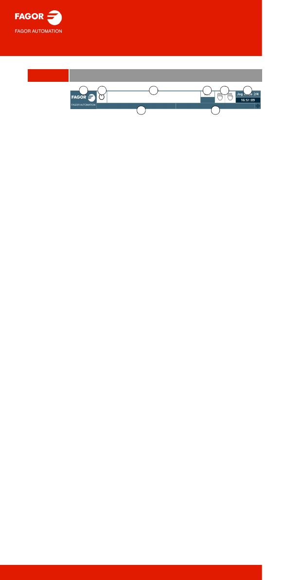
General description of the interface.
A. Icon (customizable) identifying the manufacturer.
Clicking with the mouse or pressing on a touch-
screen, the CNC shows the task window (same as
pressing the keystroke sequence [CTRL]+[A]) that
shows the list of the work modes, user modes, OEM
modes and CNC hotkey modes.
B. Icon showing the status of the program of the active
channel:
C. Program selected in the active channel for execution.
Clicking with the mouse or pressing a touch-screen
has the same effect as the [Main-Menu] key, which
shows the initial screen of the CNC.
D. Number of the last Nxxxx label executed. The bottom
icon indicates whether the Single-block execution
mode is active.
E. Number of channels available and active channel
(indicated in blue). Icons indicate which execution
mode (Manual, Automatic or MDI), or simulated
execution (theoretical, G functions, G S M and T
functions, fast and fast [S=0]) is found in each
channel. Clicking with the mouse or pressing a touch-
screen to access the desired channel, doing it on the
icon of the active channel, has the same effect as the
[ESC] key.
F. Active work mode (automatic, manual, etc.) selected
screen number and total number of screens
available. System clock. By clicking on the active
work mode, the CNC shows the list of available
pages and which ones are visible.
G. Active CNC message. If the "+" symbol is displayed
on the right hand side of the CNC message, this
means that there are other CNC messages on other
channels.
H. PLC messages. If the "+" symbol appearing on the
right of the PLC message is blue, this means that
there is more than 1 active PLC message. To see the
other active messages, click it with the mouse or tap
it on the touch-screen or press [CTRL + M].
A B C D E F
G H
Screen and keys
7
Description of the keys
Monitor & keyboard.
Function keys.
Softkeys.
Keys F1 through F12 select the options of the softkey
menus.
Browsing keys.
NEXT key. Screen change.
Key that can be configured by the machine
manufacturer (OEM).
FOCUS key.
It is used to switch between the different windows of the
screen.
BACK key. (*)
On the horizontal softkey menu, it may be used to go
from a softkey submenu up to the previous menu. The
ESC key performs the same function.
Help key.
HELP key.
Display CNC help.
Work modes.
Automatic mode.
Manual mode.
EDISIMU mode.
MDI/MDA mode.
User tables (zero offsets, fixtures and arithmetic
parameters).
Tool and magazine table.
Utilities mode.
Configurable mode.
OEM configurable table.
(*) The BACK key is not available on all keyboards.
Screen and keys
8
(*) The calculator key is not available on all keyboards.
Browsing keys.
Main menu.
Multifunction key:
• Change the active icon status.
• When editing conversational cycles, a copy of the
selected profile can be made.
• In conversational mode, it alternates between the
standard screen and auxiliary screen.
• In ISO mode, it opens and closes dynamic percentage
control (dynamic override).
The SPACE key (space bar) performs the same function.
Keys to move the cursor.
The arrow keys move the cursor one position to the left,
right, up or down.
The previous-page or next-page keys show the
previous or next page at the part-program or PLC
program editor.
The home and end keys move the cursor the beginning
or end of the line.
The tab key moves the cursor to the next field of the
active menu.
Editing keys.
Delete.
Delete.
Insert or overwrite.
It also inserts the cycle being edited by the program
called by the cycle itself, or inserts the calculator value
at the call calculator point.
Escape key, to cancel the current action without
assuming the changes.
Key to validate commands, data and program blocks of
the editor.
It allows for the recuperation and modification of a
program profile or a cycle that has already been edited.
Calculator (*).
Screen and keys
9
Jog panel
Turn the CNC off.
Turn the CNC off.
To choose Shut down, Cancel or Restart.
Jog keyboard for jogging the axes.
Keys to select axes and jog them in the positive
direction.
Keys to select axes and jog them in the negative
direction.
Keys to select the axes and keys to select the jogging
direction. Both keys (axis and direction) must be
pressed to jog the axis.
Rapid key. When pressing this key while moving an axis,
the CNC applies the rapid feedrate.
Feed selectors.
Selector of the manual movement type.
Continuous jog, incremental jog or handwheel.
• In handwheel mode, it selects the multiplying factor for
the handwheel pulses (x1, x10 o x100).
• In incremental mode, it selects the incremental value
of the axis movements.
Feedrate override % selector.
Selector of percentage of feedrate
override, between 0% and 200%,
for jog and automatic movements.
10000
1000
100
10
1
100
10
1
jog
200
190
180
170
160
150
140
130
120
110
100
90
80
70
60
50
40
30
20
10
4
2
0
FEED
Screen and keys
10
Execution keys.
Cycle start key [START].
Execute the selected program in automatic mode, a
block in MDI/MDA mode, etc.
Cycle stop key [STOP].
Interrupt the execution of the CNC.
Reset key.
It initializes the system setting the initial conditions as
defined by machine parameters.
Single block execution mode.
When selecting the "single block" execution mode, the
program simulation will be interrupted at the end of each
block.
Machine reference zero (home) search.
This key only works in MANUAL mode. It can be used
directly, where it calls the home search subroutine for all
axes, or it can be used after selecting an axis, so that
it only looks for the machine reference for that axis.
Spindle control.
Start the spindle clockwise.
Stop the spindle.
Start the spindle counterclockwise.
Percentage variation of the spindle speed.
Spindle orientation.
Speed override % selector.
Selector of percentage of spindle
speed override between 0% and
200%.
200
190
180
170
160
150
140
130
120
110
100
90
80
70
60
50
40
30
20
10
4
2
0
SPEED
Screen and keys
11
Keyboard shortcuts
Browsing keys.
[CTRL]+[F1]
Previous menu.
[CTRL]+[F2]
Switch window.
[CTRL]+[F3]
Switch screens. Configurable keys
[ALT]+[B]
Two-color key
Operations at the interface.
[CTRL] + [W]
Minimize/Maximize the CNC. It can be configured by the
machine manufacturer (OEM).
[CTRL] + [J]
Show / hide the virtual operator panel.
[CTRL] + [M]
Show / hide the PLC message list.
[CTRL] + [O]
Show / hide the CNC message list.
[ALT] + [W]
Show / hide the window for errors and warnings.
[ALT] + [F4]
Turn the CNC off.
[ALT] + [-]
Expand and collapse cycles/profiles in the editor.
[SHIFT] + [Up / Right Arrow]
Increase simulation speed.
[SHIFT] + [Down / Left Arrow]
Reduce simulation speed.
Screen and keys
12
The shortcuts for the [START] [STOP] and [RESET] keys are only
available when the CNC is installed as simulator on a PC.
Work modes.
[CTRL] + [A]
To show the task window.
[CTRL] + [SHIFT] + [F1]
Main menu.
[CTRL] + [F6]
Automatic mode.
[CTRL] + [F7]
Manual mode.
[CTRL] + [F9]
EDISIMU mode, in other words editing and simulation.
[CTRL] + [F8]
MDI/MDA mode.
[CTRL] + [F10]
User tables.
[CTRL] + [F11]
Tool and magazine table.
[CTRL] + [F12]
Utilities mode.
[CTRL] + [K]
Calculator.
Execution keys.
[CTRL]+[S]
Cycle start key [START].
[CTRL]+[P]
Cycle stop key [STOP].
[CTRL]+[R]
Reset key.
[CTRL]+[B]
Single block execution mode.
13
Jog mode
Softkey Meaning
Description of the manual mode screen.
Change the units for data display (mm or inches). For
programming, the CNC assumes the units defined with
the active function G70 or G71, or, when not
programmed, the units set by the machine
manufacturer (INCHES parameter).
Setting and activating the zero offsets and the fixture
offsets. This softkey shows the zero offsets and the
fixture offsets of the system, either to store the active
zero offset or to activate a new zero offset.
Tool calibration / measurement (·M· model).
Tool calibration / measurement (·T· model).
Part centering (·M· model).
WORK MODES
Work modes
14
Manual home search (one axis at a time)
The axis-by-axis home search cancels the zero offset, the
fixture offset and the measuring offset. The CNC assumes the
machine reference zero point (home) as the new part zero.
Keyboard.
1. Select the axis to be homed (on alphanumeric
keyboard). The CNC will highlight the coordinate of
that axis.
2. Press the homing key [ZERO]. The CNC will display
the symbol “1” in the numeric area.
3. Press [START] to go ahead with the home search or
[ESC] to cancel the operation.
Softkey menu.
1. Press the home search softkey to show the list of axes
of the channel.
2. Select the axis to be homed on the softkey menu. The
CNC will highlight the coordinate of that axis and will
show the symbol “1” in the numeric area.
3. Press [START] to go ahead with the home search or
[ESC] to cancel the operation.
X Z
...
Work modes
15
Automatic home search (with subroutine)
Keyboard.
1. Press the homing key [ZERO]. The CNC will display
the symbol “1” in the numeric area.
2. Press [START] to go ahead with the home search or
[ESC] to cancel the operation.
Softkey menu.
1. Press the home search softkey to show the list of axes
of the channel.
2. Select the “All” option on the softkey menu.
3. Press [START] to go ahead with the home search or
[ESC] to cancel the operation.
Work modes
16
Move the axes
JOG keypad.
Select an axis and move it in the positive direction.
Select an axis and move it in the negative direction.
Keys to select the axes and keys to select the jogging
direction. Both keys (axis and direction) must be
pressed to jog the axis.
Move the axis in rapid.
Jogging.
Movement in continuous jog.
In continuous jog, the axes keep
moving while the jog keyboard is
acted upon.
1. Turn the jog selector switch to the continuous JOG
position.
2. In incremental mode, it selects the incremental value
of the axis movements.
Movement in incremental jog.
In incremental jog, the axis moves
a specific distance every time the
key is pressed.
1. Turn the jog selector switch to one of the incremental
jog positions.
2. Jog the desired axis using the JOG panel (keypad).
Every time the JOG panel is acted upon, the axis will
move the distance indicated on the dial of the jog
selector switch.
10000
1000
100
10
1
100
10
1
jog
10000
1000
100
10
1
100
10
1
jog
jog
Work modes
17
Jogging
(via handwheel).
General handwheel (it may be used to jog any axis
of the machine).
1. Turn the jog selector switch to one of the handwheel
positions.
2. Select the axis or axes to be jogged on the jog
keyboard. The CNC will highlight the selected axes.
3. Once the axis has been selected, the CNC will move
it as the handwheel is turned depending on the setting
of the selector switch and on the turning direction of
the handwheel.
Individual handwheel (it is associated with a
particular axis).
1. Turn the jog selector switch to one of the handwheel
positions.
2. The CNC moves each axis as its relevant handwheel
is turned depending on the setting of the selector
switch and on the turning direction of the handwheel.
10000
1000
100
10
1
100
10
1
jog
Work modes
18
Coordinate preset (temporary offset)
The [ESC] key may be used to cancel the operation at any time.
Keyboard.
1. Select the axis to be preset (on alphanumeric
keyboard). The CNC will highlight the coordinate of
that axis.
2. Key in the desired preset value.
3. Press [ENTER] to assume the entered value.
Keyboard (using the calculator).
1. Select the axis to be preset (on alphanumeric
keyboard). The CNC will highlight the coordinate of
that axis.
2. Open the calculator using the [CALC] key or by
pressing [CTRL] + [K]. The value shown by the axis
goes directly into the calculator and any operation
can be performed (for example: /2 [ENTER]).
3. Press the [INSERT] key to directly enter the value of
the calculator for the selected axis.
4. Press [ENTER] to assume the entered value.
Softkey menu.
1. Press the softkey for presetting axes to show the list
of axes of the channel and select an axis. The CNC
will highlight the coordinate of that axis.
2. Key in the desired preset value.
3. Press [ENTER] to assume the entered value.
X Z
...
Work modes
19
Move an axis to a particular position
The [ESC] key may be used to cancel the operation at any time.
Keyboard.
1. Select the axis to be moved (on alphanumeric
keyboard). The CNC will highlight the coordinate of
that axis.
2. Enter the coordinate of the target point.
3. Press [START] to make the move.
Keyboard (using the calculator).
1. Select the axis to be moved (on alphanumeric
keyboard). The CNC will highlight the coordinate of
that axis.
2. Open the calculator using the [CALC] key or by
pressing [CTRL] + [K]. The value shown by the axis
goes directly into the calculator and any operation
can be performed (for example: /2 [ENTER]).
3. Press the [INSERT] key to directly enter the value of
the calculator for the axis to be moved.
4. Press [START] to make the move.
Softkey menu.
1. Press the softkey for presetting axes to show the list
of axes of the channel and select an axis. The CNC
will highlight the coordinate of that axis.
2. Enter the coordinate of the target point.
3. Press [START] to make the move.
X Z
...
Work modes
20
Set the feedrate, speed or tool
Feedrate.
1. Press [F] at the alphanumeric keyboard.
2. Enter the new feedrate directly or with the calculator
if a calculated value is to be used.
3. Press [START] to assume the entered value or [ESC]
to cancel the operation.
Speed.
1. Press [S] at the alphanumeric keyboard until
selecting the desired spindle. When pressing this key
for the first time, the CNC will highlight the relevant
data indicating that it is selected.
2. Enter the new spindle speed.
3. Press [START] to assume the entered value or [ESC]
to cancel the operation.
Tool.
1. Press [T] on the alphanumeric keyboard.
2. Enter the tool to be selected.
3. Press [START] to assume the entered value or [ESC]
to cancel the operation.
Note: this command initiates a tool change that may
require the movement of axes and mechanical parts of
the machine.
  • Page 1 1
  • Page 2 2
  • Page 3 3
  • Page 4 4
  • Page 5 5
  • Page 6 6
  • Page 7 7
  • Page 8 8
  • Page 9 9
  • Page 10 10
  • Page 11 11
  • Page 12 12
  • Page 13 13
  • Page 14 14
  • Page 15 15
  • Page 16 16
  • Page 17 17
  • Page 18 18
  • Page 19 19
  • Page 20 20
  • Page 21 21
  • Page 22 22
  • Page 23 23
  • Page 24 24
  • Page 25 25
  • Page 26 26
  • Page 27 27
  • Page 28 28
  • Page 29 29
  • Page 30 30
  • Page 31 31
  • Page 32 32
  • Page 33 33
  • Page 34 34
  • Page 35 35
  • Page 36 36
  • Page 37 37
  • Page 38 38
  • Page 39 39
  • Page 40 40
  • Page 41 41
  • Page 42 42
  • Page 43 43
  • Page 44 44
  • Page 45 45
  • Page 46 46
  • Page 47 47
  • Page 48 48
  • Page 49 49
  • Page 50 50
  • Page 51 51
  • Page 52 52
  • Page 53 53
  • Page 54 54
  • Page 55 55
  • Page 56 56
  • Page 57 57
  • Page 58 58
  • Page 59 59
  • Page 60 60
  • Page 61 61
  • Page 62 62
  • Page 63 63
  • Page 64 64
  • Page 65 65
  • Page 66 66
  • Page 67 67
  • Page 68 68
  • Page 69 69
  • Page 70 70
  • Page 71 71
  • Page 72 72
  • Page 73 73
  • Page 74 74
  • Page 75 75
  • Page 76 76
  • Page 77 77
  • Page 78 78
  • Page 79 79
  • Page 80 80
  • Page 81 81
  • Page 82 82
  • Page 83 83
  • Page 84 84
  • Page 85 85
  • Page 86 86
  • Page 87 87
  • Page 88 88
  • Page 89 89
  • Page 90 90
  • Page 91 91
  • Page 92 92
  • Page 93 93
  • Page 94 94
  • Page 95 95
  • Page 96 96
  • Page 97 97
  • Page 98 98
  • Page 99 99
  • Page 100 100
  • Page 101 101
  • Page 102 102
  • Page 103 103
  • Page 104 104
  • Page 105 105
  • Page 106 106
  • Page 107 107
  • Page 108 108
  • Page 109 109
  • Page 110 110
  • Page 111 111
  • Page 112 112
  • Page 113 113
  • Page 114 114
  • Page 115 115
  • Page 116 116
  • Page 117 117
  • Page 118 118
  • Page 119 119
  • Page 120 120
  • Page 121 121
  • Page 122 122
  • Page 123 123
  • Page 124 124
  • Page 125 125
  • Page 126 126
  • Page 127 127
  • Page 128 128
  • Page 129 129
  • Page 130 130
  • Page 131 131
  • Page 132 132
  • Page 133 133
  • Page 134 134
  • Page 135 135
  • Page 136 136
  • Page 137 137
  • Page 138 138
  • Page 139 139
  • Page 140 140
  • Page 141 141
  • Page 142 142
  • Page 143 143
  • Page 144 144
  • Page 145 145
  • Page 146 146
  • Page 147 147
  • Page 148 148
  • Page 149 149
  • Page 150 150
  • Page 151 151
  • Page 152 152
  • Page 153 153
  • Page 154 154
  • Page 155 155
  • Page 156 156
  • Page 157 157
  • Page 158 158
  • Page 159 159
  • Page 160 160
  • Page 161 161
  • Page 162 162
  • Page 163 163
  • Page 164 164
  • Page 165 165
  • Page 166 166
  • Page 167 167
  • Page 168 168
  • Page 169 169
  • Page 170 170

Fagor CNC 8060 User manual

Type
User manual

Ask a question and I''ll find the answer in the document

Finding information in a document is now easier with AI