Page is loading ...

Operation Manual
OM Series
Quarter - Turn Electrical Actuator
Dixon Sanitary
N25 W23040 Paul Road • Pewaukee, WI 53072
ph: 800.789.1718 • fx: 800.789.4046
dixonvalve.com

2 Dixon Sanitary 800.789.1718 • dixonvalve.com
Table of Contents
Overview...............................................................................................................................................................................................4
Important Notices
.................................................................................................................................................................................5
Standard Mounting
............................................................................................................................................................................... 6
Specication
......................................................................................................................................................................................... 7
Storage Information
..............................................................................................................................................................................8
Lubrication
............................................................................................................................................................................................9
Installation
..........................................................................................................................................................................................10
Wiring Diagram
...................................................................................................................................................................................11
OM-1, OM-A, OM-A-M, 12V, 24V DC On-Off Controller ...............................................................................................................12
OM-1, OM-A, OM-A-M, 12V, 24V AC On-Off Controller ...............................................................................................................13
OM-1, OM-A, OM-A-M, 110V, 220V AC 1-Phase On-Off Controller.............................................................................................14
OM-1, OM-A, OM-A-M, 110V, 220V AC 1-Phase On-Off Controller, 75% duty cycle .................................................................. 15
OM-1, OM-A, OM-A-M, 110V, 220V AC 1-Phase On-Off Controller, Coupling Board ..................................................................16
OM-1, OM-A, OM-A-M, 110V, 220V AC 1-Phase On-Off Controller, Analog Signal Output.........................................................17
OM-1, OM-A, OM-A-M, 24V AC/DC On-Off Controller, Analog Signal Output ............................................................................18
OM-1, OM-A, OM-A-M, 24V DC Modulating Controller ................................................................................................................19
OM-1, OM-A, OM-A-M, 24V AC Modulating Controller.................................................................................................................20
OM-1, OM-A, OM-A-M, 110V, 220V AC 1-Phase Modulating Controller .....................................................................................21
OM-1, OM-A, OM-A-M, 24V AC Modulating Controller, MODBUS ..............................................................................................22
OM-1, OM-A, OM-A-M, 24V DC Modulating Controller, MODBUS..............................................................................................23
OM-1, OM-A, OM-A-M, 110V, 220V AC 1-Phase Modulating Controller, MODBUS ....................................................................24
OM-2 to OM-6 12V DC On-Off Controller ..................................................................................................................................... 25
OM-2 to OM-12, OM-F, OM-G 24V DC On-Off Controller ............................................................................................................ 25
OM-2 to OM-6 12V AC On-Off Controller .....................................................................................................................................26
OM-2 to OM-12, OM-F, OM-G 24V AC On-Off Controller ............................................................................................................26
OM-7 to OM-10 12V DC On-Off Controller ................................................................................................................................... 27
BM-2, OM-2 to OM-13, OM-F, OM-G 110V, 220V AC 1-Phase On-Off Controller .......................................................................28
OM-2 to OM-13, OM-F, OM-G 110V, 220V AC 1-Phase On-Off Controller, Coupling Board .......................................................29
BM-2, OM-2 to OM-13 220V, 380V, 440V AC 3-Phase On-Off Controller....................................................................................30
OM-2 to OM-8 110V, 220V AC 1-Phase On-Off Controller, 75% duty cycle ................................................................................ 31
OM-9 to OM-13, 110V AC 1-Phase On-Off Controller, 50% duty cycle ........................................................................................32
OM-9 to OM-13, 220V AC 1-Phase On-Off Controller, 50% duty cycle ........................................................................................33
OM-2 to OM-13, 110V, 220V AC 1-Phase On-Off Controller, Analog Signal Output....................................................................34
OM-2 to OM-13, 220V, 380V, 440V AC 3-Phase On-Off Controller, Analog Signal Output .........................................................35
OM-2 to OM-6 12V DC Modulating Controller ..............................................................................................................................36
OM-2 to OM-12, OM-F, OM-G 24V DC Modulating Controller ..................................................................................................... 36
OM-2 to OM-12, OM-F, OM-G 24V AC Modulating Controller......................................................................................................37
OM-2 to OM-8, OM-F, OM-G 110V, 220V AC 1-Phase Modulating Controller .............................................................................38
OM-2 to OM-13, 220V, 380V, 440V AC 3-Phase Modulating Controller ...................................................................................... 39

3Dixon Sanitary 800.789.1718 • dixonvalve.com
Table of Contents (continued)
OM-2 to OM-8 110V, 220V AC 1-Phase Modulating Controller, 75% duty cycle..........................................................................40
OM-9 to OM-13, 110V AC 1-Phase Modulating Controller, 50% duty cycle .................................................................................41
OM-9 to OM-13, 220V AC 1-Phase Modulating Controller, 50% duty cycle .................................................................................42
OM-2 to OM-13, 110V, 220V AC 1-Phase On-Off Controller, Local Control Unit .........................................................................43
OM-2 to OM-13, 220V, 380V, 440V AC 3-Phase On-off Controller, Local Control Unit ............................................................... 44
OM-2 to OM-8 110V, 220V AC 1-Phase Modulating Controller, Local Control Unit ....................................................................45
OM-2 to OM-8 110V, 220V AC 1-Phase Modulating Controller, Local Control Unit, 75% duty cycle ...........................................46
OM-9 to OM-13, 110V AC 1-Phase Modulating Controller, Local Control Unit, 50% duty cycle .................................................. 47
OM-9 to OM-13, 220V AC 1-Phase Modulating Controller, Local Control Unit, 50% duty cycle .................................................. 48
OM-2 to OM-13, 110V, 220V AC 1-Phase On-off Controller, Local Control Unit, Analog Signal Output ......................................49
OM-2 to OM-13, 220V, 380V, 440V AC 3-Phase On-off Controller, Local Control Unit, Analog Signal Output ........................... 50
BM-2, OM-A, OM-A-M, OM-1 to OM-13, OM-F, OM-G 110V, 220V AC 1-Phase Same Switch Coupling Wiring ........................51
Adjustment – Travel Cam & Limit Switches........................................................................................................................................52
Adjustment - Mechanical Stops
..........................................................................................................................................................55
Adjustment – Modulating Control Board
.............................................................................................................................................56
Part A: Suitable for OM-1 to OM-13, OM-A, OM-A-M, OM-F, OM-G ............................................................................................56
Part B: Suitable for OM-1 to OM-13, OM-A, OM-A-M (MODBUS optional) ..................................................................................62
Trouble Shooting
................................................................................................................................................................................ 74
Warranty
.............................................................................................................................................................................................76

4 Dixon Sanitary 800.789.1718 • dixonvalve.com
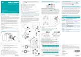
Overview
Features:
• 30% duty cycle at rated torque
• Self-locking function, allows a smooth running, dependable robust drive system
• Built-in thermal protection prevents motor burning out. AC motor is 257°F (125°C) and 194°F (90°C) for DC motor (the 75% duty
cycle actuator uses DC motor)
• Models are ISO 5211 compliant
• Visual position indicator on top of actuator cover and manual override (except BM-2 and OMA)
• Manual operation is non-clutch design that can be operated without any lever, clutch or brake upon power outage. Design is
patented in Taiwan, U.S. and China.
Model Maximum Torque Weight Manual Override
N•m lb•in Kg lb
OM-A 50 443 3 6.61 N/A
OM-A-M 50 443 3 6.61
Lever
OM-1 35 310 2 4.41
BM-2 120 1063 5.5 12.13 N/A
OM-F 65 576 11 24.25
Hand-wheel
OM-2 90 797 11 24.25
OM-G 90 797 11 24.25
OM-3 150 1328 11 24.25
OM-4 400 3542 20 44.09
OM-5 500 4427 20 44.09
OM-6 650 5756 20 44.09
OM-7 1000 8855 32 70.55
OM-8 1500 13282 32 70.55
OM-9 2000 17709 71 156.53
OM-10 2500 22137 71 156.53
OM-11 3000 26564 72 158.73
OM-12 3500 30991 72 158.73
OM-13 4500 39846 106 233.69

5Dixon Sanitary 800.789.1718 • dixonvalve.com
Important Notices
Caution!
1.
Check for correct voltage prior to wiring.
2. Turn power off before servicing or for maintenance purpose.
3. Use sealant to seal conduit connections after wiring to prevent dusting or water contamination.
4. The angle of electric actuator installation must be between 0 to 180 degree. Do not install upside down or below the horizontal.
5. When more than one electric actuator needed to operate simultaneously, please connect with the individual cables or install the
coupling board.
6.
Not intended for vacuum spaces and avoid installing near explosive atmospheres.
7. Actuators should be placed at clean and dry place for storage, and protected with outer carton from being affected by great
temperature difference or serious vibration.
8.
To avoid functional failure caused by statics, do not touch any components on the PCB with metal tools or bare hands.
9. Please connect the ground wire to PE inside the electric actuator.
10. The warranty period of our products is one year.
Duty Cycle - Compliance to IEC Standard
"Duty cycle" means the starting frequency.
The formula: Running Time ÷ (Running time + Rest Time) × 100% = duty cycle
Rest Time = Running Time × (1- duty cycle) ÷ duty cycle
For example: The running time for OM-2 is 15 seconds.
30% duty cycle 15 × [ ( 1 – 30%) / 30% ] = 35 → The rest time will be 35 seconds.
75% duty cycle 15 x [ ( 1 – 75%) / 75% ] = 5 → The rest time will be 5 seconds.
If the duty cycle is higher, the rest time will be shortened. It means the starting frequency will be higher.

6 Dixon Sanitary 800.789.1718 • dixonvalve.com
Standard Mounting
Model
Mounting
Flange
Shaft Depth of Shaft Key
(ISO 5211) mm inch mm inch mm inch
BM-2 F07 22 0.87 30 1.18 N/A
OM-A
OM-A-M
OM-1
OM-F, OM-G
OM-2 to OM-3
OM-4 to OM-6
F05 / F07
F05 / F07
F03 / F05
F07
F07
F10
17
17
14
22
22
36
0.67
0.67
0.55
0.87
0.87
1.38
20
20
17
30
30
40
0.78
0.78
0.67
1.18
1.18
1.57
N/A
N/A
N/A
N/A
N/A
N/A
OM-7 to OM-8
OM-9 to OM-12
OM-13
F12 or F14
F14 OR F16
F16 / F25
35
75
72
1.38
2.95
2.83
60
100
110
2.36
3.94
4.33
10x10
12x10
20x12
0.39x0.39
0.47x0.39
0.79x0.47

7Dixon Sanitary 800.789.1718 • dixonvalve.com
Specication
Model
No.
Maximum Torque Speed
(90°)
Motor
Power
12V DC/AC 24V DC/AC
Nm lb-in Run Start Lock Run Start Lock
BM-2 - - - - - - - - - -
OM-A 50 443 20s 10W 1.3A 1.5A 2.8A 0.8A 0.9A 1.6A
OM-A-M 50 443 20s 10W 1.3A 1.5A 2.8A 0.8A 0.9A 1.6A
OM-1 35 310 15s 10W 1.9A 2.0A 2.8A 1.1A 1.1A 1.6A
OM-2 90 797 15s 40W 3.4A 5.2A 16.5A 2.2A 4.5A 14.5A
OM-F 65 576 6s 60W - - - 2.6A 3.8A 11.0A
OM-3 150 1328 22s 40W 4.4A 4.9A 16.5A 2.4A 5.0A 14.5A
OM-G 120 1063 8s 60W - - - 4.4A 4.8A 11.0A
OM-4 400 3542 16s 80W 16.1A 16.1A 33.0A 8.5A 9.2A 30.0A
OM-5 500 4427 22s 80W 14.1A 13.5A 33.0A 7.5A 9.0A 30.0A
OM-6 650 5756 28s 80W 12.3A 12.5A
33.0A 7.0A 8.5A 30.0A
OM-7 1000 8855 46s 80W - - - 6.8A 7.8A 30.0A
OM-8 1500 13282 46s 80W 25A 26A 59A 8.1A 8.0A 30.0A
OM-9 2000 17709 58s 80W - - - 8.8A 11.0A 26.0A
OM-10 2500 22137 58s 80W 28A 60A 59A 11.8A 11.0A 26.0A
OM-11 3000 26564 58s 220W - - - 15.1A 11.0A 33.0A
OM-12 3500 30991 58s 220W - - - 17.8A 12.0A 33.0A
Single Phase
Model
No.
Maximum Torque Speed (90°) Motor
Power
110V Current 220V-240V Current
Nm lb-in 60 Hz 50 Hz Run Start Lock Run Start Lock
BM-2 120 1063 8s 10s 40W 1.3A 1.6A 1.6A 0.6A 0.9A 0.9A
OM-A 50 443 20s 24s 10W 0.6A 0.6A 0.7A 0.3A 0.4A 0.5A
OM-A-M 50 443 20s 24s 10W 0.6A 0.6A 0.7A 0.3A 0.4A 0.5A
OM-1 35 310 12s 13s 10W 0.6A 0.6A 0.7A 0.3A 0.4A 0.4A
OM-2 90 797 15s 17s 40W 1.0A 1.8A 1.6A 0.5A 0.8A 0.9A
OM-F 65 576 6s 6s 60W 1.4A 2.1A 3.1A 0.7A 1.0A 1.5A
OM-3 150 1328 22s 26s 40W 1.2A 1.8A 1.6A 1.0A 1.2A 0.9A
OM-G 120 1063 8s 8s 60W 1.6A 3.0A 3.1A 0.8A 1.2A 1.5A
OM-4 400 3542 16s 18s 80W 1.9A 3.8A 3.6A 1.1A 2.0A 2.2A
OM-5 500 4427 22s 25s 80W 2.0A 3.8A
3.6A 1.1A 2.0A 2.2A
OM-6 650 5756 28s 31s 80W 2.1A 3.8A 3.6A 1.1A 2.0A 2.2A
OM-7 1000 8855 46s 55s 120W 3.1A 8.5A 9.0A 1.4A 4.1A 5.0A
OM-8 1500 13282 46s 55s 120W 3.3A 9.0A 9.0A 1.6A 4.4A 5.0A
OM-9 2000 17709 58s 70s 180W 3.3A 5.8A 5.9A 2.1A 3.8A 3.6A
OM-10 2500 22137 58s 70s 180W 4.0A 6.5A 5.9A 2.3A 4.0A 3.6A
OM-11 3000 26564 58s 70s 180W 4.5A 3.5A 5.9A 2.5A 4.2A 3.6A
OM-12 3500 30991 58s 70s 220W 4.0A 8.0A 7.5A 2.4A 4.4A 4.8A
OM-13 4500 39846 80s 95s 220W 4.2A 8.0A 7.5A 2.4A 4.8A 4.8A

8 Dixon Sanitary 800.789.1718 • dixonvalve.com
Specication
Three Phase
Model
No.
Maximum
Torque
Speed (90°) Motor
Power
220V Current 380V Current 440V Current
Nm lb-in 60 Hz 50 Hz Run Start Lock Run Start Lock Run Start Lock
BM-2 120 1063 8s 10s 40W 0.8A 1.4A 1.5A 0.4A 0.9A 0.7A 0.4A 0.5A 0.6A
OM-1 - - - - - - - - - - - - - -
OM-A - - - - - - - - - - - - - -
OM-A-M - - - - - - - - - - - - - -
OM-2 90 797 15s 17s 40W 0.8A 1.4A 1.5A 0.4A 0.7A 0.7A 0.4A 0.9A 0.6A
OM-3 150 1328 22s 26s 40W 0.8A 1.4A 1.5A 0.4A 0.7A 0.7A 0.4A 0.9A 0.6A
OM-4 400 3542 16s 18s 80W 1.0A 1.8A 2.3A 0.7A 1.3A 1.5A 0.6A 1.4A 1.4A
OM-5 500 4427 22s 25s 80W
1.0A 1.8A 2.3A 0.7A 1.3A 1.5A 0.6A 1.4A 1.4A
OM-6 650 5756 28s 31s 80W 1.0A 1.8A 2.3A 0.7A 1.3A 1.5A 0.6A 1.4A 1.4A
OM-7 1000 8855 46s 55s 120W 0.9A 2.0A 2.2A 0.7A 1.2A 1.4A 0.5A 1.3A 1.3A
OM-8 1500 13282 46s 56s 120W 1.0A 2.4A 2.6A 0.7A 1.5A 1.5A 0.6A 1.2A 1.2A
OM-9 2000 17709 58s 70s 180W 1.3A 3.7A 3.9A 0.7A 2.0A 2.3A 0.7A 2.0A 2.2A
OM-10 2500 22137 58s 70s 180W 1.3A 3.4A 3.9A 0.7A 2.0A 2.4A 0.7A 2.0A 2.2A
OM-11 3000 26564 58s 70s 180W 1.3A 3.5A 3.9A 0.7A 2.0A 2.4A 0.7A 2.0A 2.2A
OM-12 3500 30991 58s 70s 220W 1.5A 4.8A 5.4A 0.9A 2.5A 2.5A 0.8A 2.6A 2.4A
OM-13 4500 39846 80s 95s 220W 1.5A 4.9A 5.4A 1.0A 2.5A 2.5A 0.8A 2.6A 2.4A
Note: Run - Full Load Ampere
Lock - Locked Rotor Ampere

9Dixon Sanitary 800.789.1718 • dixonvalve.com
Storage Information
Receiving / Inspection
1. Carefully inspect for shipping damage. Damage to the shipping carton is usually a good indication that it has received rough
handing. Report all damage immediately to the freight carrier and your seller.
2.
After unpacking the product and information packet, please take care to save the shipping carton and any packing material in case
of product return or replacement. Verify that the item on the packing list or bill of lading is the same as your own documentation. If
there is any discrepancy, please contact with the seller.
Storage
1. If the actuator cannot be installed immediately, store it in a dry place, it must be protected from excess moisture, dust, and weather
until you are ready to connect cables.
2.
If the actuator has to be installed but cannot be cabled, please don’t remove the plastic transit cable entry plugs. When the
actuator has to be cabled, it is recommended to replace to suitable water-proof plugs with IP protection.
Lubrication
• The gear train has been permanently lubricated at the factory sufcient.

10 Dixon Sanitary 800.789.1718 • dixonvalve.com
Installation
1. Before mounting actuator, verify that the torque requirement is less than the output torque of the actuator. (The suggested safety
factor is 30% of the maximum torque of valve).
For example:
If the maximum torque of 5" valve is 80N•m → 80 × 1.3 (safety factor) = 104N•m
104N•m < 150N•m (OM-3) → OK!
104N•m > 90N•m (OM-2) → NO!
2. Check if the output shaft ts to the stem of valve before inserting into actuator. Please use mounting plate or adaptor to connect
if it does not match.
3. Insert output shaft adaptor into actuator. Make sure it ts satisfactory.
4. Determine that actuator position, open or closed, matches with position of equipment prior to mounting. Use manual override to
change position if necessary.
5. Remove valve's manual device and mount on the proper connection.
CAUTION: Don't remove any necessary parts for the proper operation of the valve.
6. Check again that the valve and actuator are in the same position.
7. Install the actuator to valve directly or with mounting kits, then tighten all screws and nuts.
8. Remove actuator cover.
CAUTION: Be sure power is off at the main power box.
9. Wire actuator using the wiring diagram inside cover.
CAUTION: For the 3-Phase on-off controller actuator, please use the hand-wheel to turn the actuator to 45 degree before test.
If the operating direction is opposite after supplying power, please change any two of the U, V, W.
10. Supply power to actuator.
CAUTION: Use remarkable mark warning "there are live circuits that could cause electrical shock or death".
11. Make sure if it is needed to calibrate the fully-open or fully-closed position of the actuator. Refer to the P49 to P52 to set the
fully-open or fully-closed position and mechanical stops
12. If the actuator is modulating type, refer to P56 to P73 to set the functions.
CAUTION: Turn power off before changing any setting.
13. Replace cover and secure cover screws.

11Dixon Sanitary 800.789.1718 • dixonvalve.com
Wiring Diagram
1. MC1 & MC2: Electromagnetic contactor
2. NFB: No fuse breaker
3. C.S.: Control switch
4. C: Capacitor
5. N: Neutral
6. L: Live Wire
7. PE: Protective Earth
8. O.L.: Over-load relay
9. H: Heater
10. LS: Limit switch
11. TS: Torque switch
12. Switch(1): Local/Remote Control. Switch(2): Open/Stop/Close select
13. Duty cycle (Standard Model):
BM-2, OM-A, OM-A-M, OM-F, OM-G, OM-1 to OM-13: 30% duty cycle
Extended duty cycle:
OM-A, OM-A-M, OM-1 to OM-8: 75% duty cycle
OM-9 to OM-13: 50% duty cycle
14. LS1: Limit switch for open
LS2: Limit switch for close
15. The usage for 2 additional limit switches:
OM-1, OM-A, OM-A-M
LS3 Fully-Open: Terminal "A" connects to terminal "B"
LS4 Fully-Closed: Terminal "A" connects to terminal "E"
OM-1, OM-A, OM-A-M (Option: MODBUS)
LS3 Fully-Open: Terminal "A" connects to terminal "C"
LS4 Fully-Closed: Terminal "D" connects to terminal "F"
BM-2, OM-A, OM-AM, OM-F, OM-G, OM-2 to OM-13
LS3 Fully-Open: Terminal "A" connects to terminal "C"
LS4 Fully-Closed: Terminal "D" connects to terminal "F"
NOTE!
When a set of control wires or switch needs to control two or more actuators at the same time, please refer to P51 or install the
coupling board.

12 Dixon Sanitary 800.789.1718 • dixonvalve.com
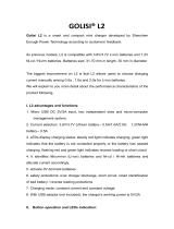
Wiring Diagram - Quarter Turn Actuator
• OM-1, OM-A, OM-A-M 12V, 24V DC
• On-Off Controller
Note:
1. "+" connects to #1, "—" connects to #7
2. "—" connects to #3 for "OPEN", "—" connects to #4 for "CLOSE"
3. Using less than 3A current for "A, B, C, E, F"
4. Using battery to supply power for DC units

13Dixon Sanitary 800.789.1718 • dixonvalve.com
Wiring Diagram - Quarter Turn Actuator
• OM-1, OM-A, OM-A-M 12V, 24V AC
• On-Off Controller
Note:
1. "N" connects to #1, "L" connects to #7
2. "L" connects to #3 for "OPEN", "L" connects to #4 for "CLOSE"
3. Using less than 3A current for "A, B, C, E, F"

14 Dixon Sanitary 800.789.1718 • dixonvalve.com
Wiring Diagram - Quarter Turn Actuator
• OM-1, OM-A, OM-A-M 110V, 220V AC 1-Phase
On-Off Controller
Note:
1. "N" connects to #1, "L" connects to #7
2. "L" connects to #3 for "OPEN", "L" connects to #4 for "CLOSE"
3. Using less than 3A current for "A, B, C, E, F"

15Dixon Sanitary 800.789.1718 • dixonvalve.com
Wiring Diagram - Quarter Turn Actuator
• OM-1, OM-A, OM-A-M 110V, 220V AC 1-Phase
• On-Off Controller, 75% duty cycle
Note:
1. "N" connects to #1, "L" connects to #7
2. "L" connects to #3 for "OPEN", "L" connects to #4 for "CLOSE"
3. Using less than 3A current for "A, B, C, E, F"

16 Dixon Sanitary 800.789.1718 • dixonvalve.com
Wiring Diagram - Quarter Turn Actuator
• OM-1 , OM-A, OM-A-M 110V, 220V AC 1-Phase
• On-Off Controller, Coupling Board
Note:
1. "N" connects to #1, "L" connects to #7
2. "L" connects to #3 for "OPEN", "L" connects to #4 for "CLOSE"
3. Using less than 3A current for "A, B, C, E, F"

17Dixon Sanitary 800.789.1718 • dixonvalve.com
Wiring Diagram - Quarter Turn Actuator
• OM-1 , OM-A, OM-A-M 110V, 220V AC 1-Phase
• On-Off Controller, Analog Signal Output
Note:
1. "N" connects to #1, "L" connects to #7
2. "L" connects to #3 for "OPEN", "—" connects to #4 for "CLOSE"
3. Using less than 3A current for "A, B, C, E, F"
4. JP5 : 2 to 10V or 1 to 5V output mode: J2 : 2 to 10V or 1 to 5V output signal

18 Dixon Sanitary 800.789.1718 • dixonvalve.com
Wiring Diagram - Quarter Turn Actuator
• OM-1, OM-A, OM-A-M 24V AC/DC
• On-Off Controller, Analog Signal Output
Note:
1. "N" connects to #1, "L" connects to #7
2. "L" connects to #3 for "OPEN", "—" connects to #4 for "CLOSE"
3. Using less than 3A current for "A, B, C, E, F"
4. JP5: 2 to 10V or 1 to 5V output mode: J2: 2 to 10V or 1 to 5V output signal

19Dixon Sanitary 800.789.1718 • dixonvalve.com
• OM-1, OM-A, OM-A-M 24V DC
• Modulating Controller
Wiring Diagram - Quarter Turn Actuator
Note:
1. Modulating Board
a. Input signal: 4 to 20mA, 1 to 5V, 2 to 10V
It is suggested to use the shielding wire and its length should not exceed 30m.
b. Output Signal: 4 to 20mA, 2 to 10V
2. Using less than 3A current for "A, B, C, E, F"
3. Using battery to supply power for DC units

20 Dixon Sanitary 800.789.1718 • dixonvalve.com
Wiring Diagram - Quarter Turn Actuator
• OM-1 , OM-A, OM-A-M 24V AC
• Modulating Controller
Note:
1. Modulating Board
a. Input signal: 4 to 20mA, 1 to 5V, 2 to 10V
It is suggested to use the shielding wire and its length should not exceed 30m.
b. Output Signal: 4 to 20mA, 2 to 10V
2. Using less than 3A current for "A, B, C, E, F"
/