Philips 15MF605T/17 User manual

Category
TVs & monitors
Type
User manual

This manual is also suitable for

Horizontal frequencies
F1-15"30 - 49kHz
F1-20"30 - 40KHz
Service
Service
Service
TABLE OF CONTENTS
Published by BCU Monitors Printed in suzhou Copyright reserved Subject to modification F Jan . 21 2005
Description Page
Important Safety Notice------------------------------- 2
Technical Data/Installation------------------------3~8
On-Screen Display/Aging Mode------------------9~11
Trouble shooting--------------------------------------14
Failure Mode Of Panel/Wiring Diagram---------15~16
Warning message/Factory Mode----------------12~13
Mechanical/Electrical Instructions-------------17~22
Display adjustment-------------------------------23~24
DDC DATA/Instructions--------------------------25~32
ISP Instructions----------------------------------33~34
Block /DC/DC POWER Diagram-----------------35~36
PC-IN/SCART Diagram---------------------------37~38
VIDEO-IN/VIDEO DECODER Diagram----------39~40
Description Page
T/T DECODER Diagram------------------------------41
MCU/Scaler Diagram----------------------------42~43
SRAM/Panel Interface Diagram----------------44~45
Sound DECODER/Audio Diagram--------------46~47
Scaler Board C.B.A------------------------------48~49
Key And IR Diagram/C.B.A---------------------50~51
YPbPr-IN/Inverter Diagram/C.B.A-------------52~56
Exploded View--------------------------------------- 57
Recommended/Spare/Different parts list----58~62
Repair Tips/Repair Flow Chart-----------------63~66
General product specification------------------67~90
Circuit description-------------------------------90~91
Safety Test Requirements---------------------------92
REFER TO BACK COVER FOR IMPORTANT SAFETY GUIDELINES
CAUTION: USE A SEPARATE ISOLATION TRANSFORMER FOR THIS UNIT WHEN SERVICING.
ANY PERSON ATTEMPTING TO SERVICE THIS CHASSIS MUST FAMILIARIZE HIMSELF WITH THE CHASSIS
AND BE AWARE OF THE NECESSARY SAFETY PRECAUTIONS TO BE USED WHEN SERVICING ELECTRONIC
EQUIPMENT CONTAINING HIGH VOLTAGES.
SAFETY NOTICE
F1-15" F1-20"
GB 3138 106 10444
F1 LCD Monitor/TV
15MF605T/17
20MF605T/17
Important Safety Notice
2Magnavox LCD TV
Go to cover page
Proper service and repair isimportant to the safe, reliable
operation of all HPConsumer Electronics Company**
Equipment. The service procedures recommended by HP and
described in this service manual are effective methods of
performing service operations. Some ofthese service
operations require the use of tools specially designed for the
purpose. The special tools should be used when and as
recommended.
It is important to note that this manual contains various
CAUTIONS and NOTICES which should be carefully read in
order to minimize the risk of personal injury to service
personnel. The possibility exists that improper service
methods may damage the equipment. It is also important to
understand that these CAUTIONS and NOTICES ARE NOT
EXHAUSTIVE. HP could not possibly know, evaluate and
advise the service trade of all conceivable ways in which
service might be done or of the possible hazardous
consequences of each way. Consequently, HP has not
undertaken any such broad evaluation. Accordingly, a
servicer who uses a service procedure or tool which is not
recommended by HP must first satisfy himself thoroughly that
neither his safety nor the safe operation of the equipment will
be jeopardized by the service method selected.
* * Hereafter throughout this manual, HP Consumer
Electronics Company will bereferred to as HP.
Critical components having special safety characteristics are
identified with a bythe Ref. No. inthe parts list and
enclosed within a broken line*
(where several critical components are grouped in one area)
along with the safety symbol on the schematics or
exploded views.
Use of substitute replacement parts which do not have the
same specified safety characteristics may create shock, fire,
or other hazards.
Under no circumstances should the original design be
modified or altered without written permission from Philips.
Philips assumes no liability, express or implied, arising out of
any unauthorized modification of design.
Servicer assumes all liability.
*BrokenLine
WARNING
Take care during handling the LCD module with backlight
unit
- Must mount the moduleusing mounting holes arranged infour
corners.
- Do not press onthe panel, edge of theframe strongly or electric
shock as this will result in damage to the screen.
- Do not scratch orpress on the panel withany sharp objects, such
as pencil or pen asthis may result in damage to the panel.
- Protect the module fromthe ESD as it maydamage the electronic
circuit (C-MOS).
- Make certain that treatment person s body are grounded through
wrist band.
- Do not leave themodule in high temperature andin areas of high
humidity for a long time.
- Avoid contact with water as it may ashort circuit within the module.
- If the surface ofpanel become dirty, please wipe it off with a soft
material. (Cleaning with a dirty or rough cloth may damage the
panel.)
FOR PRODUCTS CONTAINING LASER :
DANGER- Invisible laser radiation when open.
AVOID DIRECT EXPOSURE TO BEAM.
CAUTION- Use of controls or adjustments or
performance of procedures other than
those specified herein may result in
hazardous radiation exposure.
CAUTION- The use of optical instruments with this
product will increase eye hazard.
TO ENSURE THE CONTINUED RELIABILITY OF THIS
PRODUCT, USE ONLY ORIGINAL MANUFACTURER'S
REPLACEMENT PARTS, WHICH ARE LISTED WITH THEIR PART
NUMBERS IN THE PARTS LIST SECTION OF THIS
SERVICE MANUAL.
3
Technical Data(15MF605T/17) Magnavox LCD TV
Go to cover page
1. General
1.1. Product description
This 15 LCD Monitor/TV is specified as a display peripheral with
analog video signal input and include TV function with 15 TFT
LCD display.
Horizontal scan range is 30 -
49KHz and refresh range is65 -62
Hz.
This scan range allows it to display resolution up to1024*768
non-interlaced at60 Hz efresh rate. The image can be adjust through
OSD control, these adjustments can be stored on a board memory
Including 11 factory pre -load modes.
1.2. Basic data
1.2.1. LCD
1.2.1.1 LPL panel
Type NR. : LC150X02
Display area(mm) : 304.128(H) x 228.096(V) (15.0-inch diagonal)
Number of Pixels : 1024(H) x 768(V)
Pitch ( mm ) : 0.297(H)x 0.297(V)
Color pixel arrangement : RGB vertical stripes
Displayoperatingmode : Transmissive mode,normally white
Color depth : 16M colors( 6 bits with FRC)
Brightness (cd/m^2) : 450(cd/m^2)(Center 1 points Typ.)
Viewing angle (CR>10) : -65 ~ 65 (H), -55 ~ 45 (V)(Typ.)
Surface treatment :Hard coating(3H) &Anti-glare (Haze 13%)
Electrical interface : LVDS (1 pixel/clock)
Response Time : 16ms(typ.) (Tr+Tf)
Power Consumption (W) : 16.9(typ.)
Contrast ratio : Typical 400 : 1
Module size (mm) : 332.8(W) x 262.8(H) x 18.0(D)
Module weight (g) : 1750
Backlight : 4 CCFL
1.2.1.2.AUO panel
Type NR. : T150XG01
Display area(mm): 304.128(H) x 228.096(V) (15.0-inch diagonal)
Number of Pixels : 1024(H) x 768(V)
Pitch ( mm ) : 0.297(H) x 0.297(V)
Color pixel arrangement : RGB vertical stripes
Displayoperatingmode : TN mode, normally white
Color depth : 16M colors( 6 bits with FRC)
Brightness (cd/m^2) : 450 nit (typ. )@ 6.0mA
Viewing angle (CR>10) : -70 ~ 70 (H), -60 ~ 60 (V)(Typ.)
Surface treatment :Hard coating(3H) &AG
Electrical interface :1ch LVDS (8bit)
Response Time : 16ms(typ.) (Tr+Tf)
Power Consumption(W) : 22 (typ.)@ 6.0mA
Contrast ratio : Typical 450 : 1
Module size (mm) : 32 6.5(W) x 253.5(H) x 14.4(D) (typ.)
Module weight (g) : 1350
Backlight : 4 CCFL
1.2.1.3.CPT panel
Type NR. : CLAA150XP03
Display area(mm) :30.4.1(H) x 228.1(V) (15.0-inch diagonal)
Number of Pixels : 1024(H) x 768(V)
Pitch ( mm ) : 0.297(H) x 0.297(V)
Color pixel arrangement : RGB vertical stripe
Displayoperatingmode : Normally white,TN
Color depth : 16.2M colors( 6 bits with FRC)
Brightness (cd/m^2) : 400nit(typ.) (center, 6.5mA)
Viewing angle (CR>10) : -70 ~ 70 (H), -60 ~ 65 (V)(Typ.)
Surface treatment :Anti-glare
Wide viewing angle
technology : Optical Compensation Film
Response Time : 16ms(typ.)
Power Consumption(W) :17.1 (typ.)
Contrast ratio : Typical 500 : 1
Module size (mm) : 32 6.5(W) x 253.5(H) x 14.0(D) (typ.)
Module weight (g) : 1300
Backlight : CCFL, 4 tables, edge-light (top/bottom)
1.2.2. Power supply
AC/DC Power adapter: +16V DC/3.75A (100V~240V)
Power consumption: 40 W (typical)
Power cord length and type: 1.8M, USA type
Power indicator : LED (On:Green ,Sleeping mode: Amber )
Auto power saving : EPA
1.2.3. Horizontal scan : 30- 49KHz
1.2.4. Vertical scan : 56 - 62 Hz
1.2.5. Input signals
1.PC Signal type
Analog Video: 0.7 Vp-p Linear , positive polarity
Sync : TTL level , separate , positive or negative polarity
2.TV signal type
RF signal : Aerial input
Video signal : S-video input
CVBS
YPbPr
3.Audio signal : S-video L/R ,YPbPr L/R audio input
PC line in
1.2.6 Input connectors
(1) Input analog D-sub connector pin assignment:
Sync polarity :
-Hori.sync positive/negative
-Vert.sync positive/negative
4Magnavox LCD TV
Go to cover page
1. General
1.1. Product description
This 20 LCD Monitor/TV is specified as a display peripheral with
analog video signal input and include TV function with 20 TFT
LCD display. Horizontal scan range is 30-40K Hz and refresh
rate 56-62Hz.
This scan range allows it to display resolution up to 800*600
non-interlaced at 60 Hz refresh rate. The image can be adjust
through OSD control, these adjustments can be stored on a board
memory including 8 factory pre-load modes.
1.2. Basic data
1.2.1 LCD panel
Type NR. :A201SN02 (AUO)
Display area(mm) : 408(H) x 306(V) (20.1-inch diagonal)
Display mode : TN type, Normal white + SWV film
Number of Pixels : 800(H) x 600(V)
Pitch ( mm ) : 0.51(H) x 0.51(V)
Color pixel arrangement : RGB vertical stripes
Display mode : normally white TN
Number of color : 16.7M ( 8 bits)
Brightness (cd/m^2) : 450nit(typ.)
Viewing angle : -80 ~80 (H), -60 ~60 (V)(Typ.)
Response time : 16ms typ. (Tr+Tf)
Surface treatment : Hard Coating + AR
Electrical interface : TTL (1 port)
Total module power(W) : 35W(typ.)
Contrast ratio : Typical 500 : 1
Overall dimension (mm) : 448(W) x 347(H) x 23(D)(max.)
Module weight (g) : 3500
Backlight : 6 CCFL
**Income inspection, please refer to panel specification.**
1.2.2. Power supply
Power consumption : Operating 55 W (typical)
Power cord length : 1.8M
Power cord type : USA type
Power indicator : LED (On: Green ,Sleeping mode: Amber )
Auto power saving : EPA
1.2.3. Horizontal scan : 30 - 40KHz
1.2.4. Vertical scan : 56 - 62 Hz
1.2.5.Input signals
1.PC Signal type
Analog Video: 0.7 Vp-p Linear , positive polarity
Sync : TTL level , separate , positive or negative polarity
2.TV signal type
RF signal : Aerial input
Video signal : S -video input
CVBS
YPbPr
3.Audio signal : S -video L/R ,YPbPr L/R audio input
PC line in
1.2.6 Input connectors
(1) Input analog D-sub connector pin assignment:
Sync polarity :
-Hori.sync positive/negative
-Vert.sync positive/negative
"
"
5
Installation Magnavox LCD TV
Go to cover page
Before installation
Before proceed to install yournewLCDTV,pleasefollow thesteps
and diagrams as shownto familiarizeyourselfwith thecorrect and safe
way ofunfolding thebase.
1.Placethesetfacing down on a flatsurfaceand aprotectivesheet.
2.Unfold thebasefollowing thedirection as shown on thediagram.
3.Placethesetup
right, you LCD TV is now ready forinstall.
INSTALLINGLCD TV ON THE WALL
Thestand ofyourLCD TV is comply with Standard VESA 75 standard,
ifyou intend to install theLCDTVonthewall, pleaseconsult a
professional technician forproper installing.Themanufacture accepts
no liability forinstallations not performedbyprofessional technician.
Television and remotecontrol
Battery installation
1. Plug theDC adapter into theDC IN 16V jack on the
LCD TV. Plug thepower cableinto an outlet.
2. Press POWER to turnontheLCD TV.
3. Press VOLUME + to increasethesound level. Or,
press VOLUME to lower thesound level.
4. Press CH+ orCH-toselect channels.
5. Point theremotecontrol towardonthefront oftheLCD TV
whenoperating theLCD TV with theremote.
6. Removethebattery compartment lid on theback oftheremote.
7. Placetwo AAA batteriesintheremote.Be sure the(+) and ( -)
ends ofthebatterieslineup as marked insidethe
battery compartment.
8. Reattach thebattery compartment lid.
Installation
6Magnavox LCD TV
Go to cover page
1.Power : Power On/Standby
2.Numerica keys : (0~9) ,Channel setting
3.Mute : Sound mute function
4.Prev-CH : Recall previous CH
5.Menu : Main menu select and OK key
6.VOL- : Left/Volume Down
7.OK : OK
8.Source : Source select for PC,Tuner,CVBS,S-video,HD
9.Closed cap. : Closed caption on/off
10.SAP(2nd audio) : Sound select
11.CH- : Down/Channel Down
12.PIP : PIP size select (Small/Medium/Large/PBP)
13.VOL+ : Right/Volume Up
14.CH+ : Up/ Channel Up
15.Display Format : Select display format (4:3, Expand 4:3,
Compress 16:9)
16.Smart Sound : Select sound effect
(Personal/News/Music/Theatre)
17.Smart Picture : Select picture effect (Personal/Movie/Sports/
weak signal/multimedia/Night)
18.Sleep Timer : Sleep timer 15,30,60,120,180,240 OFF
1
2
3
4
5
6
7
8
9
10
11
12
13
14
15
16
17
18
ANTENNA CONNECTION
Acombination antenna receives normal broadcast channels
(VHF 2 13 and UHF 14 69). Your connection is easy because
there is only one 75 (ohm) antenna jack on the back of
your TV, and that s where the antenna goes.
BASIC CABLE TV CONNECTION
Your Cable TV signal into your home may be a single, 75 (ohm) cable.
If so, this connection is very simple. Follow the step below to connect
your Cable TV signal to your new LCD TV.
1.Connect the Cable TV signal to one end of the supplied L-Adapter as
shown, and connect the other end of the adapter to the TV jack on the
LCD TV.
CABLE BOX CONNECTIONS
If you have a Cable Box, follow either set of these steps to complete
your connections.
Cable Box with RF In/Out Jacks
This connection will not supply Stereo sound to the LCD TV.
1.Connect the Cable TV signal to the IN jack
(or RF IN or CABLE IN) on the Cable Box.
2.Connect an RF coaxial cable (not supplied) to the OUT
jack (or TO TV or RF OUT) of the Cable Box.
3.Connect the other end of the coaxial cable to one end of the supplied
L-Adapter as shown, and connect the other end of the adapter to the TV
jack on the LCD TV.
4.Plug the DC adapter into the DC IN 16V jack on the LCD TV. Plug the
power cable into an outlet.
5.Set the Channel 3/4 (or Output channel) switch of the Cable Box to 3
or 4. Set the TV to the same channel. When watching TV programming,
change channels at the Cable Box, not the LCD TV.
7
Installation Magnavox LCD TV
Go to cover page
Cable Box with Audio/Video Out Jacks This connection will supply
Stereo sound to theLCD TV.
1. Connect the Cable TV signal to the IN jack (or RF IN or CABLE IN)
on the Cable Box.
2. Using an RCA-type video cable (not supplied) connect one end of
the Videocable to the Video Out jack of the Cable Box.Connect the
other end of the cable tothe yellow VIDEO jack on the side of theTV.
Video cablesare usually marked withyellow and are available from
Magnavox orelectronics retailers. Video jacks on most equipment
are yellow.
3. Using RCA-type, stereo audio cables (not supplied), connect one
end of the cablesto the left and right Audio Out jacks of the Cable Box.
Connect the other end of thatcable to the Audio jack on the side of the
LCD TV. Audio cables are usually markedwith red and white and are
available fromMagnavox or electronics retailers
.The rightaudio jack is
red and the left audio jack is white. Match the cable colors to the jack
colors.
4. Plug the DC adapter into the DC IN 16V jack on the LCD TV.
Plug the power cableinto an outlet.
AUDIO/VIDEO INPUT CONNECTIONS
The AUDIO and VIDEO In jacks on the rear of the LCD TV enable
quick connections of other equipment. Connect a VCR, DVD
Player, Video Game, Camcorder,etc., to these jacks. To view the
materialplaying on the other equipment, Set the LCD TV to its AV
Mode.
1. Connect a RCA-style video cable(usually yellowor marked
CVBS) To the VIDEO OUT jacks of the other equipment (DVD
Player, Camcorder,etc.) and to the yellow VIDEO jack on the side
of the LCD TV.
2. Connect RCA-style audio cables (usuallyred and white) to the
AUDIO OUT (leftand right) jacks on the other equipment. Connect
the other end of the cables to the AUDIO jack on the side of the
LCD TV.
3.Plug the DC Adapter into the DC IN 16V jack on the TV. Plug the
power cable into an outlet. Turn on the TV and otherequipment.
4.Press the Source button to set the TV to AV Mode.
5.Press PLAY on the other equipment to view its material on the TV.
The S-Video connection on the rear of the
LCD TV can provide you with better LCD picture detail and clarity for
the playbackof accessory sources such as DBS (digital broadcast
satellite), DVD (digital video discs), video games, and VHS VCR
(videocasse tte recorder) tapes than the normal antenna picture
connections.
Note: The accessory device must have an S-VIDEO OUT (put) jack
in orderfor you to complete the connection on this page.
1. Connect an S-Video cable to the S-VIDEO jack of the other
equipment(DVD Player,Camcorder, etc.) and to the S -VIDEO jack
on the rear of the LCD TV.
2. Connect RCA-style audio cables (usually
red and white) to the AUDIO OUT (left and right) jacks on the other
equipment.Connect the other end of the cables to the AUDIO
jack on the side of the LCD TV.
3.Plug the DC Adapter into the DC IN 16Vjack on the LCD TV.
Plug the power cableinto an outlet. Turn on the LCD TV and
other equipment.
4.Press the Source button to setthe LCD TV to its S-VIDEO mode.
5.Press PLAY on the other equipment toview its material on the
LCD TV.
Installation
8Magnavox LCD TV
Go to cover page
COMPONENT (YPBPR) CONNECTIONS
Component Video input provide the highest possible color and picture
resolution in the playback of digital signal source material, such as with
DVD players.
Note: The accessory device must have an component(YPbPr) output
jack in order for you to complete the connection on this page.
1. Connect the component (Y, Pb, Pr) Video OUT jacks from the
DVD player(or similar device) to the COMP(onent) VIDEO Input jacks
on the bottom of the LCD TV.
2.Connect the red and white AUDIO CABLES to the Audio (left ad right)
output jacks on the rear of the accessory device to the AUDIO IN jack.
Connect the other end of the cable to the Audio jack on the rear of
LCD TV.
3. Plug the DC Adapter into the DC IN 16 V jack on the LCD TV.
Plug the power cable into an outlet. Turn on the LCD TV and
other equipment.
4.Press the SOURCE button on the remote control to select HD.
HD will appear in the upper left corner on the TV screen.
5.Insert a DVD disc into the DVD player and press the PLAY button
on the DVD Player.
PC (MONITOR) CONNECTION
This LCD TV can be used as a PC . Your computer will have to be
Equipped with a VGA type video output and VGA cable.
1. Connect one end of the VGA Video cable (not supplied) to the
Monitor(video) output on the computer, while connecting the other ends
to the VGA INPUT jack on the LCD TV.
2. Although audio connections are not required, the LCD TV can
Reproduce the computers audio out by an AUDIO ADAPTER to the
Audio output jack on the computer (if available) while connecting the
other ends of the Audio cables to the PC AUDIO Jacks on the bottom
of the TV.
3.Plug the DC Adapter into the DC IN 16V jack on the LCD TV. Plug the
power cable into an outlet. Turn on the LCD TV and PC.
4.Press the SOURCE button until PC MODE appears on the screen.
9
On Screen Display Magnavox LCD TV
Go to cover page
PC MODE
1st Layer 2nd Layer 3rd Layer
PICTURE
SMART PICTURE NORMAL
WARM
COOL
BRIGHTNESS
CONTRAST
AUTO ADJUST YES
IN PROGRESS
STORE? YES
NO
MANUAL ADJUST PHASE
CLOCK
HORIZONTAL
VERTICAL
AUDIO
SMART SOUND PERSONAL
NEWS
MUSIC
THEATRE
SETTINGS TREBLE
BASS
BALANCE
STEREO STEREO
VIRTUAL SURROUND VIRTUAL SURROUND
OFF
AVL YES
NO
FEATURES
PIP SIZE OFF
SMALL
MEDIUM
LARGE
PBP
VIDEO TV
AV
S-VIDEO
COMPONENT
AUDIO PC
PIP
DISPLAY ICON1
ICON2
ICON3
ICON4
SOURCE PC
TV
AV
S-VIDEO
HD
INSTALL
LANGUAGE ENGLISH
FRANÇ AIS
ESPAÑ OL
FACTORY RESET YES?
TV / AV/ S-VIDEO / HDTV MODE
1st Layer 2nd Layer 3rd Layer 4th Layer 5th Layer
PICTURE
SMART PICTURE PERSONAL
MOVIES
SPORTS
WEAK SIGNAL
MULTIMEDIA
NIGHT
BRIGHTNESS
CONTRAST
COLOR
SHARPNESS
TINT
AUDIO
SMART SOUND PERSONAL
NEWS
MUSIC
THEATRE
On Screen Display
10 Magnavox LCD TV
Go to cover page
AUDIO SETTINGS TREBLE
BASS
BALANCE
STEREO STEREO
SAP
MONO
VIRTUAL SURROUND VIRTUAL SURROUND
OFF
AVL YES
NO
FEATURES
SOURCE PC
TV
AV
S-VIDEO
HD
PICTURE FORMAT 4:3
EXPAND 4:3
COMPRESS 16:9
PICTURE ALIGNMENT
AUTO LOCK LOCK PROGRAM
CHANGE CODE YES
CLEAR ALL ON
OFF
BLOCK OPTION ON
OFF
MOVIE RATING G ON/OFF
PG ON/OFF
PG13 ON/OFF
RON/OFF
NC17 ON/OFF
XON/OFF
TV RATING TV Y ON/OFF
TV Y7 BLOCK ON/OFF
FV ON/OFF
TV G ON/OFF
TV PG BLOCK ON/OFF
V ON/OFF
S ON/OFF
L ON/OFF
D ON/OFF
TV 14 BLOCK ON/OFF
V ON/OFF
S ON/OFF
L ON/OFF
D ON/OFF
TV MA BLOCK ON/OFF
V ON/OFF
S ON/OFF
L ON/OFF
CLOSED CAPTION CAPTION MODE CC1
CC2
CC3
CC4
TXT1
TXT2
TXT3
TXT4
CC MUTE
CC DISPLAY ON
OFF
INSTALL
LANGUAGE ENGLISH
FRANÇ AIS
ESPAÑ OL
TUNER MODE ATENNA
CABLE
AUTO
AUTO PROGRAM START?
CHANNEL EDIT CHANNEL
SKIPPED ACTIVE
SKIPPED
MANUAL FINE TUNE
FACTORY RESET YES?
11
Aging Mode Magnavox LCD TV
Go to cover page
AGING...
After55seconds, bring up:
After5seconds, bring up:
AGING...
After55seconds, bring up:
----------
----------
repeatly
Connect Signalcable again=> go back tonormaldisplay
Access Aging.. Mode
Step1:Select thesource"PC"and then turnoff LCD-TV,and disconnect
InterfaceCablebetween Monitorand PC.
Step2:[Push "power " button and then push the"VOL-"and "VOL+"
buttonsatthesametimeimmediately and holdit] untill comesout
"AGING screen"then releaseall buttons.
Bring up:
ATTENTION
NO VIDEO INPUT
ATTENTION
NO VIDEO INPUT
Warning Message
12 Magnavox LCD TV
Go to cover page
1.Automatic adjustment (for factory only)
Press Volume+ and Volume- on front key at the same time (PC mode
only). It adjusts PC image to the best and save the screen automatically.
2. OUT OF RANGE
If PC input timing is out of range, it shows OUT OF RANGE warning
message on the center of the screen. The range of horizontal frequency
is between 14 - 63 KHz. The range of vertical frequency is between
45 - 76 Hz. The OSD won t timeout.
3.NO VIDEO INPUT
When PC input timing has either horizontal frequency or vertical
frequency. Or neither has horizontal frequency nor vertical frequency.
It shows on the center of the screen for 30 seconds, then it will enter
sleep mode.
""
'
13
Factory Mode Magnavox LCD TV
Go to cover page
Access factory.Mode
howto get into factory mode menu
Step1:Select thesource "PC"and then turn off LCD-TV.
Step2:[Push "power "button and then push the"VOL-"and "VOL+"
buttonsat thesametimeimmediately and holdit]aboutfive seconds
then releaseall buttons.
Press "menu"button and bring up factory mode indication asshownin
Fig.1
UsetheCHNNEL-and CHNNEL+to select the"F1/FL1 NAFTAV1.01.
05 041208 LG15XGA" and then press the"VOL+" button
MAIN CONTROLS
SMARTPICTURE
AUDIO BRIGHTNESS
FEATURES CONTRAST
INSTALL AUTOADJUST
MANUALADJUST
1024X768@60HZ
PICTURE
1024X768@60HZ
F1/FL1 NAFTAV1.01.05 041208 LG15XGA
Fig.1
MenuItemDescription
Scalar GainRGB Scalar Gainfor Normal/Warm/CoolinPCmode.
Auto-Color Adjust color fromreceived signal(either inPCor
HDTV mode).
ADC Offset RGB AdjustAD9883for PCADC offset.
ADC GainRGB AdjustAD9883for PCADC gain.
PCOffset RGB PCanalog scalar offset.
711XSDTV Brightness AdjustSA 7119 SDTV brightness.
711XSDTV SAT.AdjustSA 7119 SDTV saturation.
711XSDTV ContrastAdjustSA 7119 SDTV contrast.
711XSDTV TINTAdjustSA 7119 SDTV tint (hue).
TV ShiftHVAdjustTVscreen position horizontally/vertically.
HDShiftHVAdjustHDTV screen position
horizontally/vertically.
ShowLock Message ShowOSDlock message.
HDTV ADC Offset RGB AdjustAD9883for HDTV ADC offset.
HDTV ADC GainRGB AdjustAD9883for HDTV ADC gain.
Video Scalar GainRGB Adjustscalar gainfor Video mode.
Scalar HueAdjustscalar hue.
Trouble shooting
14 Magnavox LCD TV
Go to cover page
No Power
.Check the TV power cord. Disconnect the power cord from the
power outlet for 10 seconds, then reinsert the plug into the outlet.
Press POWER to turn on the TV again.
.Make sure the outlet is not on a wall switch.
.Make sure a fuse has not blown at the power outlet.
No Picture
.Check the antenna or Cable TV connections. Connect the antenna or
Cable TV signal securely to the TV’s 75ohm jack on the rear of the TV.
.Set TUNER MODE correctly. Details are on page 15.
.Activate AUTO PROGRAM to find all available channels.
In case you hear only sound and don’t see any picture in S-Video or
Video (CVBS) mode. Please check if you have connected Video signal
to S-Video or Video (CVBS) input. Only one of the two video inputs can
be connected to sound. This means that the same sound can be heared
in S-Video and Video (CVBS) mode.
No Sound
.Press the VOL+ and VOL- buttons to adjust the volume.
.Press the MUTE button on the remote control to cancel or restore the
volume.
.If you have connected other equipment to the TV (such as a VCR or
DVD Player), make sure the audio cables are connected securely
between the TV and the other equipment.
.Check the SOUND settings.
.In case you hear wrong sound in S-Video or Video (CVBS) mode.
Please check if you have connected the right sound signal to AV in
(S-Video or Video input). Only one of the two video inputs can be
connected to sound, but both video signals can be connected.
This means that only one of the two sound inputs can be heared in
S-Video and Video (CVBS) mode.
Remote Control does not work.
.Check the batteries. If necessary, replace them with two AAA heavy
duty (zinc chloride) or alkaline batteries.
.Clean the remote control as well as the remote control sensor on the
front of the TV.
.Check the TV power cord. Disconnect the power cord from the power
outlet for 10 seconds, then reinsert the plug into the outlet. Press POWER
to turn on the TV again.
.Make sure the outlet is not on a wall switch.
.Make sure a fuse has not blown at the power outlet.
.Always point the remote control toward the front of the TV (toward the
remote sensor).
.Make sure that you use the supplied Magnavox Remote control, only the
supplied Magnavox Remote control can be used with this LCD-TV set.
TV displays wrong channel or no channels.
.Repeat channel selection.
.Add the channel number(s) into the TV’s memory. Use STORE.
.Make sure TUNER MODE is set correctly.
Then activate AUTO PROGRAM to set up all available channels.
15
Magnavox LCD TV
Go to cover page
Failure description Phenomenon
Vertical block defect
Vertical dim lines
Vertical lines defect
(Always bright or dark)
Horizontal block defect
Horizontal dim lines
Horizontal lines defect
(Always bright or dark)
Has bright or dark pixel
Polarizer has bubbles
Foreign material inside
polarizer. It shows liner or
dot shape.
Concentric circle formed
Bottom back light of LCD is
brighter than normal
Back light un-uniformity
Backlight has foreign material.
Black or white color, liner or
circular type
Quick reference for failure mode of LCD panel
this page presents problems that could be made by LCD panel.
It is not necessary to repair circuit board. Simply follow the mechanical
instruction on this manual to eliminate failure by replace LCD panel.
Failure Mode Of Panel
16 Magnavox LCD TV
Go to cover page
Wiring diagram
17
Magnavox LCD TV
Go to cover page
Frontview
Back view, removethecover asFig.2
Fig.1
Fig.2
Removethebase:
unscrew the screws asFig.3
Fig.3
Removetheback cover,
unscrew the screws asFig.4 andtheopenthe
clicks andthenremovetheback cover asFig.5 Fig.6 Fig.7
Fig.4
Fig.6
Fig.7
RemovetheMatel frame board
-Removethefive screws
-Removethematel frame board asshowninFig.8
Fig.8
Removetheinverter board ,YPbPr-inandscaler board
unscrew the screws anddisconnect the connectorasshowninFig.9
Fig.5
18 Magnavox LCD TV
Go to cover page
Fig.9
Fig.10
Fig.11
Fig.12
Fig.13
Fig.14
19
Magnavox LCD TV
Go to cover page
Electrical instruction(15MF607T/17)
1.General points
1.1 During the test and measuring, supply a distortion free AC mains
Voltage to the apparatus via an isolated transformer with low
Internal resistance.
1.2 All measurements mentioned hereafter are carried out at a normal
mains voltage (90 - 132 VAC for USA version, 195 -264 VAC for
EUROPEAN version, or 90 - 264 VAC for the model with full range
power supply, unless otherwise stated.)
1.3 All voltages are to be measurement or applied with respect to
ground, unless otherwise stated.
1.4 The test has to be done on a complete set including LCD panel in a
room with temperature of 25 +/- 5 degree C.
1.5 All values mentioned in these test instruction are only applicable of
a Well aligned apparatus, with correct signal.
1.6 The letters symbols (B) and (S) placed behind the test instruction
Denotes (B): carried out 100% inspection at assembly line
(S): carried out test by sampling
1.7 The white balance (color temperature), has to be tested in subdued
Lighted room.
1.8 Repetitive power on/off cycle are allowed except it should be
avoided within 6 sec.
2. Input signal
2.1.1 PC Signal type
Analog Video : 0.7 Vp-p linear, positive polarity
Separate Sync. : TTL level, separate, positive or negative polarity
Audio signal : Mini-jack audio input
Input level: 500 mVrms ((Speaker outpout 3W when Input level
> 630mVrms and Volume control at 100%))
Signal source: pattern generator format as attachment
(table 1 to 11) Reference generator : CHROMA 2200 or 2250
2.1.2 TV Signal type
RF Signal : Aerial input, NTSC cable and antenna system.
Video signal : Cinch input, CVBS with NTSC and PAL system.
Level: 1.0Vp-p (0.7V video + 0.3V sync.)
S video input: Y/C signal, NTSC and PAL system.
Level: Y: 1.0Vp-p (0.7V video + 0.3V sync.)
C: +/- 0.3V.
Component input: Cinch G/B/R-> YPbPr cinch input.
Level: Y: 1.0Vp-p Pb/Pr: +/- 0.35V
Audio signal : Side cinch R/L for CVBS and S-video
Bottom cinch R/L for component input.
Input level: 500 mVrms ((Speaker outpout 3W when Input level
> 630mVrms and Volume control at 100%))
2.2 PC Input signal mode
PRE-LOAD VIDEO RESOLUTION
Mode 3, 6, 7, 10 are preset modes that should pass QA inspection.
Mode 1, 2, 4, 5, 8, 9, 11 will run auto adjustment only, and W/O QA
checking.
Dot rate (MHz) H.freq Mode Resolution V.freq (Hz)
1 25.175 31.469 IBM VGA 640 * 350 70.087
2 28.322 31.469 IBM VGA 720 * 400 70.087
3 25.175 31.469 IBM VGA 640 * 480 59.940
4 30.240 35.000 MACINTOSH 640 * 480 66.667
5 31.500 37.500 VESA 640 * 480 75.000
6 36.000 35.156 VESA 800 * 600 56.250
7 40.000 37.879 VESA 800 * 600 60.317
8 49.500 46.875 VESA 800 * 600 75.000
9 57.300 49.700 MACINTOSH 832 * 624 75.000
10 65.000 48.363 VESA 1024 * 768 60.004
11 78.750 60.023 VESA 1024 * 768 75.029
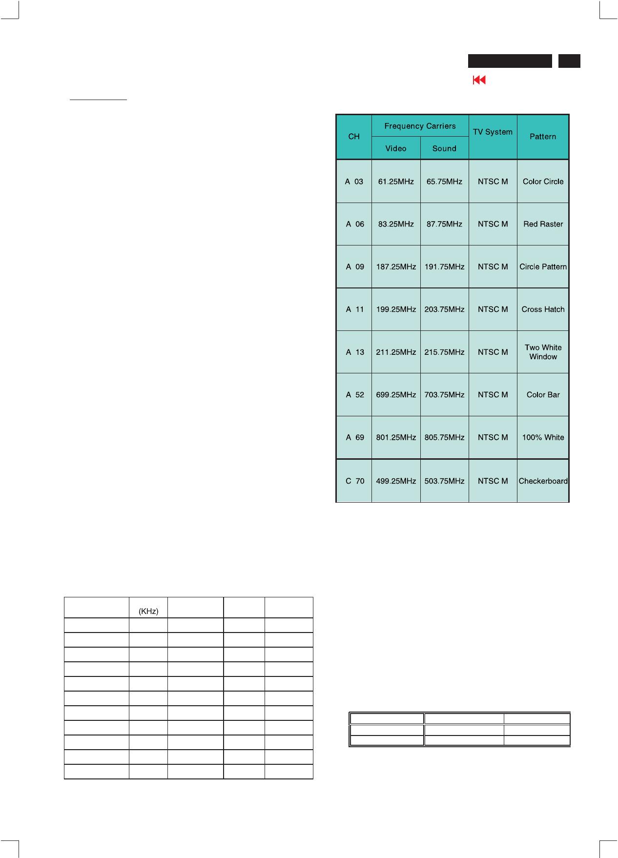
2.3 TV input signal Channel and pattern for Nafta model (Table1)
Signal Distribution Table ( NTSC)
Table 1
3. TV mode display adjust ment
3.1 White balance adjustment (B)
General set-up :
Equipment Requirements: Color analyzer.
Input requirements:
Input Signal Type : CVBS-NTSC signal.
Frequency = 187.25 MHz (CH. 9).
Alignment method:
Initial Set-up :
Set TV (7119) Brightness=124; Contrast=64, Saturate= 70 in
Factory mode (can be fine tuned)
Set Smart picture as Personal (Brightness=50, Color=50,
Contrast=50)
Apply 100% Full White/100IRE pattern by TV pattern generator.
Alignment : Adjust the VIDEO SCALER GAIN R G B in Factory
Mode
NORMAL . (See Fig 1.)
[ Enter factory menu : press Volume - and Volume + keys together
around six seconds]
The 1931 CIE chromaticity (X, Y) co-ordinates shall be:
Picture Mode X y
Normal (Original) 0.289 ±0.005 0.304 ±0.005
Table3.1: Readings with Minolta CA-110.
""
""
Electrical instruction
20 Magnavox LCD TV
Go to cover page
FACTORY ADJUST MENU
NORMAL
SCALER GAIN R G B
AUTO-COLOR (OK)
ADC OFFSET R G B
ADC GAIN R G B
PC OFFSET R G B
7119 SDTV SAT TINT
TV SHIFT H V
HD SHIFT H V
SHOW LOCK MESSAGE
HDTV ADC OFFSET R G B
HDTV ADC GAIN R G B
VIDEO SCALER GAIN R G B
SCALER HUE
EXIT Value
Fig.1
4.PC mode displayadjustment
4.1Display quality adjustment
Use timing mode as de scribe in 2.2, and use the POPO (pixel on pixel
off) patternto adjust the clock until no stripe and adjust the phase until
clear picture.(AUTO ADJUST hot key:press Volume- and Volume+
keys togetherfor 1 second.)
Check all preset 4 modes.
4.2 WHITE-D adjustment (B)
4.2.1 At factory mode apply1024X768/60Hzmode with 64 gray pattern.
Set main controls Brightness at 50% and Contrast to 50%.
Select AUTO-COLORfunction forADC OFFSETand ADC GAINsetup.
4.2.2 Set smart picture as NORMAL
Set SCALER GAIN R G B= VIDEO SCALER GAIN R G B (alignment
done).
The 1931 CIE chromaticity (X, Y) co-ordinates shall be:
Readings with Minolta CA-110.
4.2.3 Set Smart picture asWARM , and COOL The
SCALER GAIN RG B =
.
4.3 Check the analog interface cable
Check the color poor & noise condition of 64 gray pattern.
Normal/ (8500°K)
Normal/ the R’\G’\B’ are
gain after alignment.
WARM COOL
""
'
'
'
'
'
'
'
'
'
5.HDTV mode display adjust ment
5.1 White balance adjustment (B)
General set-up:
Equipment : Quantum Data Pattern Generator 801GD or 802G.
Apply 1080i, RGBWgray pattern.
(Or FLUKE 54200, apply576i, DIGITAL SCAN/DIGI_ADC1 pattern.)
Alignment method:
Initial Set-up : Set Smart picture as Personal, Brightness=50,
Color=50, Contrast=50)Set AUTO-COLOR process.
Alignments :Check chromaticity (X, Y) co-ordinates specification:
If out of specification,fine-tune HDTV ADC Gainin factory mode.
6.Preset EEPROM data
6.1 EEPROM data has to be preset data according following table.
Factory mode preset.
Function Preset value
SCALER GAIN 127 127 127
ADC Offset R/G/B 127 127 127
ADC Gain R/G/B 127 127 127
PC OFFset R/G/B 127 127 127
7119 ? brightness 124 (TV,AV,S-video,HD)
7119 Saturation 64 (TV,AV,S-video,HD)
7119 contrast 70 (TV,AV,S-video,HD)
7119 TINT 24 (TV,AV,S-video,HD)
NTSC PAL
170 181
TV shift H
TV shift V
Regular
20 22
HD SHIFT H
HD SHIFT V
See below.
HD ADC OFFset R G B 127 127 127
HD ADC GAIN R G B 127 127 127
Video Scaler Gain 127 127 127
Scaler Hue 50
Picture Mode
Factory mode:
In user Picture alignment
  • Page 1 1
  • Page 2 2
  • Page 3 3
  • Page 4 4
  • Page 5 5
  • Page 6 6
  • Page 7 7
  • Page 8 8
  • Page 9 9
  • Page 10 10
  • Page 11 11
  • Page 12 12
  • Page 13 13
  • Page 14 14
  • Page 15 15
  • Page 16 16
  • Page 17 17
  • Page 18 18
  • Page 19 19
  • Page 20 20
  • Page 21 21
  • Page 22 22
  • Page 23 23
  • Page 24 24
  • Page 25 25
  • Page 26 26
  • Page 27 27
  • Page 28 28
  • Page 29 29
  • Page 30 30
  • Page 31 31
  • Page 32 32
  • Page 33 33
  • Page 34 34
  • Page 35 35
  • Page 36 36
  • Page 37 37
  • Page 38 38
  • Page 39 39
  • Page 40 40
  • Page 41 41
  • Page 42 42
  • Page 43 43
  • Page 44 44
  • Page 45 45
  • Page 46 46
  • Page 47 47
  • Page 48 48
  • Page 49 49
  • Page 50 50
  • Page 51 51
  • Page 52 52
  • Page 53 53
  • Page 54 54
  • Page 55 55
  • Page 56 56
  • Page 57 57
  • Page 58 58
  • Page 59 59
  • Page 60 60
  • Page 61 61
  • Page 62 62
  • Page 63 63
  • Page 64 64
  • Page 65 65
  • Page 66 66
  • Page 67 67
  • Page 68 68
  • Page 69 69
  • Page 70 70
  • Page 71 71
  • Page 72 72
  • Page 73 73
  • Page 74 74
  • Page 75 75
  • Page 76 76
  • Page 77 77
  • Page 78 78
  • Page 79 79
  • Page 80 80
  • Page 81 81
  • Page 82 82
  • Page 83 83
  • Page 84 84
  • Page 85 85
  • Page 86 86
  • Page 87 87
  • Page 88 88
  • Page 89 89
  • Page 90 90
  • Page 91 91
  • Page 92 92
  • Page 93 93

Philips 15MF605T/17 User manual

Category
TVs & monitors
Type
User manual
This manual is also suitable for

Ask a question and I''ll find the answer in the document

Finding information in a document is now easier with AI