Westinghouse WFE916DSD Installation guide

Category
Cookers
Type
Installation guide

This manual is also suitable for

Westinghouse WFE916DSD features a spacious 90cm cooktop with gas burners that provide precise flame control for cooking a variety of dishes. The ceramic glass cooktop surface ensures even heat distribution and is easy to clean. The oven offers multiple cooking functions, including fan-forced cooking for even baking and roasting, and a separate grill function for grilling meats and vegetables. The separate grill function allows you to cook a variety of foods at the same time without compromising on taste or quality.

Westinghouse WFE916DSD features a spacious 90cm cooktop with gas burners that provide precise flame control for cooking a variety of dishes. The ceramic glass cooktop surface ensures even heat distribution and is easy to clean. The oven offers multiple cooking functions, including fan-forced cooking for even baking and roasting, and a separate grill function for grilling meats and vegetables. The separate grill function allows you to cook a variety of foods at the same time without compromising on taste or quality.

Installation Guide
90cm freestanding cookers
Your freestanding cooker is designed to fit into a 900mm wide gap
between standard kitchen cabinets. The appliance integrates with
the kitchen cabinets by matching the height, depth and kick panel.
The cooker may also be installed at the end of a line of benches or
with a free space either side. In addition, a slot-in type installation is
catered for allowing a continuous cabinetry kick panel to be used.
WARNING
WARNING
The cooker must be installed and serviced only by an authorised
person.
A Certificate of Compliance MUST be supplied to be kept by the
customer.
The packing materials must be removed before you install the
cooker.
The surrounding kitchen cabinets must be able to withstand 85°C.
Electrolux WILL NOT accept responsibility for damage caused by
installation into kitchen cabinets which cannot withstand 85°C.
The pipes used for installation MUST have sufficient loops so the
cooker can be moved for service (gas models).
The vents, openings and air spaces MUST NOT be blocked.
Two anti-tilt brackets are supplied and stored in the base of the
packaging
The anti-tilt brackets MUST be installed to avoid accidental
tipping (freestanding and slot-in models).
You MUST NOT lift or pull the cooker by the door handle.
The cooker MUST be checked every five years.
If the supply cord is damaged, it must be replaced by the
manufacturer, its service agent or similarly qualified persons in
order to avoid a hazard.
The appliance must not be installed behind a decorative door in
order to avoid overheating.
Due to the weight (95-100kg) and size of the cooker, 2 persons
are required to install it.
Gas model clearance requirements
Ensure the appliance is installed in accordance with clauses 6.2.5
and 6.10.1.1 of AS/NZS 5601.1 or clauses 6.9.1 and 6.9.5 of AS/
NZS 5601.2 with regard to clearances to combustible surfaces
and materials, and clearances to rangehoods and exhaust fans, to
ensure clearances of 200mm from burners to vertical combustible
surfaces. Observe the minimum dimension of 100mm from each
side of the cooker to combustible surfaces.
Clearances to combustible surfaces may be reduced if combustible
surfaces are protected in accordance with clause 6.10.1.2 of AS/NZS
5601.1, or clause 6.9.2 of AS/NZS 5601.2.
When setting the cooker height, ensure the top of the cooker is at
least 10mm higher than the level of the benchtop.
and WESTINGHOUSE are trademarks of Westinghouse Electric Corporation. Used under license by Electrolux Home Products Pty Ltd. All Rights Reserved.
© 2020 Electrolux Home Products Pty Ltd. ABN 51 004 762 341 ANC A20343401 Rev B W_INS_FS_90_Cooker_A4_Oct20
Dimensions
600mm minimum
vertical clearance
from combustible
surfaces
Gas hob 910mm
(adjustable 910-930mm)
Ceramic hob 906mm
(adjustable 906-926mm)
15mm
(height of trivet above hob)
600mm
895mm
60mm
Splashback
The splashback is secured to the back of the cooker.
REMOVE the splashback before installing the feet.
Undo this screw
to remove the
splashback.
Re-attach the
screw afterwards
1
To access your detailed user manual simply scan the QR code on your
smart phone.
For more detailed information and installation guide refer to user manual at
westinghouse.com.au/manuals
The freestanding type installation requires four screw-in feet to be
installed before it can be fitted in between cabinets, with cabinets
on one side or without adjacent cabinets. There is no clearance
requirement to adjacent side cabinets.
To ensure cooker stability, the anti-tilt brackets must be installed.
Four screw-in feet are supplied with the appliance and can be
found in the accessories pack in the oven. Select models are
supplied with a clip-on kick panel.
900mm minimum
755mm NOM
900mm NOM
600mm
both sides
Installation of feet
Freestanding appliances are supplied with four screw-in feet in
the internal accessory pack. The screw-in feet can be adjusted
by turning the lower half clockwise or anti-clockwise.
TIPS & INFORMATION
IMPORTANT
WFE904 models are supplied with two silver feet and two black
feet, it is recommended to install the two silver feet at the front
of the appliance for the best aesthetics.
If the appliance is a gas hob model, remove the burner cap
and burner crown. Store all items safely, away from the
installation area.
1. You MUST remove the oven door before commencing
installation.
Locking tab up at
normal position
Press the locking tab down for
removing the door.
Locking tab up at normal position.
Press the locking tab down for
removing the door.
Gently close the door until it comes to
a stop.Then lift the door off the hinge.
Locking tab up at normal position.
Press the locking tab down for
removing the door.
Gently close the door until it comes to
a stop.Then lift the door off the hinge.
2. Gently close the door until it comes to a stop.
Then lift the door off the hinge.
Installation Guide
90cm freestanding cookers
3. Tilt and carefully lay the appliance on its back to gain access to
the installation point for the screw in feet.
WARNING
CAUTION
To avoid scratching the floor and the appliance itself, fold the
packaging carton board and place it underneath the appliance
as protection.
The cooker MUST be laid on its back when installing the feet.
4. Install the four supplied feet via the four installation points.
Make sure that each foot is securely fastened.
Put the oven door handle
protection foam underneath the
laid down cooker to protect your
cooker when putting it upright
5. Adjust the height of the screw-in feet to make sure the hob
surface is 10mm above the bench when appliance is upright.
Bench height + 10mm minimum
6. Tilt the appliance upright by lifting the back of the hob and
pivoting it about the back two feet.
WARNING
WARNING
Heavy item! This step must be performed by two persons.
FREESTANDING INSTALLATION
2
Levelling oven
Place a level in the oven as below making sure the level sits on the
front and rear forms. Adjust the feet accordingly to level the appliance.
Installing splashback
Fit splashback to rear of hob with three screws provided.
INSTALLATION OF ANTI-TILT
BRACKET
To ensure cooker stability, the anti-tilt brackets must be installed.
There are left and right engagement slots for the anti-tilt bracket
at the bottom rear of the appliance. The following steps must be
followed to ensure the correct installation of anti-tilt brackets and
the stability of the appliance.
Anti-tilt bracket engagement slots
WARNING
CAUTION
It is not recommended to push and pull the appliance on uneven
or rough surface. Use other means to manoeuvre the appliance if
necessary.
1. Carefully push the appliance into the cabinet cavity until the back
of the oven is flush against the back wall.
2. Use non-permanent methods to mark a line on the wall along the
top surface of the splashback. This line is used as a reference line
to locate the correct location of where the anti-tilt brackets need
to be installed.
3. After the reference line is marked, pull the appliance out of the
cabinet cavity to install the anti-tilt brackets.
Anti-tilt bracket installation
reference line
WARNING
WARNING
Appropriate fasteners must be used to suit the type of wall on
which the anti-tilt brackets are installed.
Freestanding unit must be pushed up against the wall on
installation. On gas units check that the gas hose, if used,
has not been kinked during installation.
4. The anti-tilt brackets must be secured to the rear wall of the cavity
with appropriate fasteners according to dimensions in diagram.
Install anti-tilt
brackets in
this orientation
as shown
(fasteners not
supplied)
C
L
425
Anti-tilt bracket
installation
reference line
725
370 370
Freestanding installation checklist
Connect services to the appliance prior to placing into cavity.
To locate appliance, slide into cavity ensuring the anti-tilt brackets
fully engaged with the rear left and right engagement slots.
The unit must be pushed against the wall on installation.
Re-install oven door, burner body, burner caps and trivets after the
appliance is placed in the cavity.
Gas only: check that the gas hose, if used, has not been kinked
during installation
3
Installation Guide
90cm freestanding cookers
The slot-in type installation uses the appliance as
supplied. The appliance can be mounted on a plinth.
This enables a continuous cupboard kickboard to be
installed, giving a more integrated appearance. There is
no clearance requirement between oven and adjacent
side cabinets.
600mm minimum
vertical clearance
from combustible
surfaces
This surface to be level with
the top edge of the kick board
755mm
900mm
900mm
minimum
600mm
The anti-tilt brackets are to be secured to the back
wall with appropriate fasteners.
Two stops are to be screwed to the plinth in locations
as shown (stops provided). The stops locate into
slots in the base of the appliance to prevent the
product from being pulled forward when installed.
Measurements from the rear wall are to be adjusted if
there are tiles etc. that come between the appliance
and the wall.
Once services are connected, product can be lifted
onto the plinth and pushed back carefully, ensuring
the appliance engages into both brackets at the rear
and the front stops.
If the product requires removal for service, it must
be lifted at the front approximately 5mm to clear the
front stops prior to being pulled forward.
+
+
+
+
+
+
C
L
+
++
+
104
104
370 370
165 165
344 344
Location of holes for front stops
Measurements are to be adjusted to account for the
thickness of any skirting board or tiles coming between
the back of the appliance and the wall
Front stops Front stops
SLOT-IN INSTALLATION
4
Installing the clip-on kick panel
Selected models are supplied with a clip-on kick panel that can
be assembled to clip onto the front feet for a more integrated and
seamless kitchen appearance.
Assemble the clip snap onto the base.
click!
Press in both assembled clip modules into the
kick panel in the orientation as shown below.
click!
Make sure both clip modules are in the same orientation after
installation.
Clip the kick panel onto the front feet of the appliance. Make sure
the kick panel snaps onto the larger section of the front feet.
Installing the trivets
Install the middle trivet first by aligning the trivet with the wok
burner and gently placing the trivet on hob. The middle trivet is
designed to guide the location of the side trivets. Gently place
the side trivets in the orientation shown.
1
2 2
Corner support
Corner support
Self-locating tabs
Self-locating tabs
KICKPANEL INSTALLATION TRIVET INSTALLATION
5
Installation Guide
90cm freestanding cookers
The cooker MUST be installed in compliance with:
Wiring connections in AS/NZS 3000 Wiring Rules.
Local regulations, municipal building codes and other statutory
regulations.
For New Zealand Only:
The cooking range must be connected to the supply by a
supply cord fitted with the appropriately rated plug that is
compatible with the socket-outlet fitted to the final sub-
circuit in the fixed wiring that is intended to supply this
cooking range.
Supply cord size required:
WFE904/WFE915/WFE916 models - 2.5mm2
WFEP917 models - 4.0mm2
WFE946 models - 6.0mm2
The Data plate gives information about rating and is located behind
the bottom of the oven door.
A functional switch MUST be provided near the appliance in an
accessible position (AS/NZS 3000 - Clause 4.7.1).
Wiring MUST be protected against mechanical failure (AS/NZS
3000 - Clause 3.9).
Disconnection in the fixed wiring must occur in accordance with
the AS/NZS 3000 wiring rules.
The cooker MUST be properly earthed.
This range must be connected with cable of 75°C rating minimum.
This product has passed the insulation resistance test after
manufacture. If the resistance reading is low at installation, it
is probably caused by moisture from the atmosphere being
absorbed by the elements after the range has been produced.
(pass at 0.01 M AS/NZS 3000 Wiring Rules Clause 8.3.6.3).
Note: When connections are made to a multi-phase 230/240V
supply, the bridge piece MUST be removed from between the active
connections.
Rated power input
MODEL TOTAL KW A1 KW A2 KW
WFE946 13.1 3.6 9.5
TIPS & INFORMATION
IMPORTANT
Before you cook in your new oven it is important that the protective
oils used in the manufacture of the product be removed.
Make sure that the room is well ventilated (to allow smoke to
escape).
Run the grill on high for 30 minutes without grill dish.
Then run the oven on 180°C for 1 hour.
Connecting to services and commissioning
This appliance must be installed by an authorised person, according
to all codes and regulations of:
Electrical supply authorities.
Building regulations.
Local government and council authorities.
AS/NZS5601.1 (particular attention to 6.10.1 and figure 6.3, and
clause 6.10.1.11).
AS/NZS 3000 (particular attention to clause 4.7.1
and clause 3.9).
Securing points
Plastic clips
Plastic clip
Hard wiring detail
1. Remove terminal cover plate from rear panel of appliance.
2. Fit wires through hole in cover plate and make connections to
terminals.
3. Engage wires into plastic clip. Secure plastic clip with two long
silver screws (supplied in separate bag).
4. Replace cover plate onto rear panel.
GAS REQUIREMENTS
278
673
696
95
168
Gas connection point
to regulator
Electrical cable
entry point
Gas hose restraints
point to regulator
WIRING REQUIREMENTS
6
Gas connection
Read these points before connecting to the gas supply:
The appliance is preset for natural gas use, if LPG is to be used see
Conversion to LPG section.
Gas installation must be made in accordance with AS/NZS 5601.1,
the local gas fitting regulations, municipal codes and other
statutory regulations.
The gas connection point is a ½” BSP external thread located at the
rear of the appliance as shown.
The regulator is to be fitted to the manifold inlet at the rear of the
appliance and the connection is sealed using a tape or jointing
compound suitable for gas connections. The consumer piping is
then connected to the inlet of the regulator, either
1. directly, or
2. using a hose assembly and in accordance with Clause 6.10.1.9
of AS/NZS 5601.1 (High level connection) together with
the supplied elbow. The elbow is fitted to the inlet of the
regulator and oriented to allow the hose to hang downward.
The connection thread between the regulator and elbow is
sealed using a tape or jointing compound suitable for gas
connections.
This appliance is supplied set up for Natural Gas usage.
LPG CONVERSION
GAS COOKTOP MODELS
A conversion kit is included with the product for Universal LPG usage.
The conversion kit contains 5 or 7 injectors (refer to LPG conversion
table) and 1 LPG sticker.
Please follow the procedure below if a conversion to suit UNIVERSAL
LPG is required:
1. Remove the hotplate trivets, burner caps and burner crowns to
access the hotplate injectors. Replace the factory fitted injectors
with the appropriate injectors, as supplied. Refer to injector orifice
table for injector sizes. The injector size is stamped on the side of
the injector.
2. Unscrew the top hat nut from the regulator. The top hat nut and
control pressure spring assembly will disengage as an assembly.
3. Unscrew the threaded pin from top hat.
4. Upturn threaded pin, so spring is free and screw pin back into the
top hat until firm.
5. Refit the top hat nut assembly to the regulator ensuring that it
is fully screwed down. The regulator is now set for connection to
LPG.
6. Turn on the gas supply and at each new connection check for
leaks using soapy water. Each hotplate valve should be turned
on, one at a time, and the injector hole blanked off for several
seconds.
7. The operation of the regulator can be confirmed by connecting a
manometer to the pressure test point located on the side of the
regulator body adjacent to the outlet.
With the appliance operating check the outlet pressure:
when all burners of the appliance are operating at maximum,
when the smallest burner of the appliance is operating at
minimum.
Under these conditions the outlet pressure should not vary from
the nominal outlet pressure of 2.60kPa by more than ±0.52kPa.
8. If the regulator appears to not be performing satisfactorily then
check the following points:
If the outlet pressure is consistently too low then the inlet
pressure may be too low and adjustment of an upstream
Gas pressures
The following table shows the supply and operating pressures for
various gases.
GAS TYPE NATURAL GAS UNIVERSAL
LPG
Supply pressure at inlet to
appliance regulator (if fitted)
1.13 (kPa)
Minimum
2.75*
(kPa)
Operating pressure at
appliance test point 1.00 (kPa) 2.6 (kPa)
*If the regulator is placed upstream of the cooker inlet, as is normal for cookers
operating on LPG, then the supply pressure and operating pressure are the
same.
For WFE904 and WFE915 models
The following table shows the injector sizes for each burner.
INJECTOR ORIFICE NATURAL GAS UNIVERSAL
LPG
Low heat burner 1.00mm 0.55mm
Medium heat burner 1.35mm 0.70mm
High heat burner 1.60mm 0.90mm
Intense heat wok burner 1.75mm 1.00mm
For WFE916 and WFEP917 models
The following table shows the injector sizes for each burner.
INJECTOR ORIFICE NATURAL GAS UNIVERSAL
LPG
Low heat burner 1.00mm 0.55mm
Medium heat burner 1.35mm 0.70mm
High heat burner 1.60mm 0.90mm
Intense heat
dual wok burner
0.96mm
(inner)
3 x 1.07mm
(outer)
0.52mm
(inner)
3 x 0.58mm
(outer)
Checking piping size
To work out a suitable pipe size for connection use the information
in this table.
MODELS NATURAL GAS UNIVERSAL
LPG
WFE914 & WFE904 49.6 MJ/h 40.9 MJ/h
WFEP916 & WFEP917 54.2 MJ/h 45.5 MJ/h
For information and requirements about construction
and capacity of consumer piping refer to AS/NZS 5601.1 series of
standards.
7
Installation Guide
90cm freestanding cookers
NOTE: You MUST test the cooker after installation, before you hand it over
to the customer. You MUST have a manometer and a connecting tube.
regulator may be needed, or an upstream regulator or valve
with insufficient flow capacity may be present in the gas
supply line. If this is suspected then it may be necessary to
repeat the checks whilst measuring both the inlet and outlet
pressure to determine if the inlet pressure is in the range
2.75 – 7.00kPa.
Check that the insert has been fitted correctly.
Check that the turret screw is fully screwed down.
Check that the regulator has been fitted to the gas supply line
in the correct orientation, the arrow on the base of the body
indicates the direction of gas flow.
Once these checks have been completed, if the regulator still fails to
perform in a satisfactory manner it should be replaced.
9. One by one, turn the knobs to minimum and screw in the bypass
screw (accessible when the knob is removed) until a small stable
flame results. Turn the knob to maximum and then back to
minimum to ensure that the correct minimum flame is maintained.
10. Attach the LPG sticker to the cooker, near the gas supply inlet.
Cover the Natural Gas label that is factory fitted.
TESTING THE OPERATION OF THE
GAS COOKER
Checking gas supply
1. Check the manometer zero point is correct.
2. Connect the manometer to the cooker pressure test point. This is
located on the regulator or LPG inlet fitting.
3. Turn on the gas supply and the electricity and try to ignite the gas.
NOTE: It will take additional time to light the gas for the first time as air
needs to be purged from the pipes.
4. Check the operating pressure for the particular gas type.
Checking the function of the regulator
With the appliance operating check the outlet pressure:
when all burners of the appliance are operating at maximum,
when the smallest burner of the appliance is operating at minimum.
Under these conditions the outlet pressure should not vary from the
nominal outlet pressure by more than ±20% of the nominal outlet
pressure (ie ±0.20kPa for Natural Gas).
If the regulator appears to not be performing satisfactorily then check
the following points.
1. If the outlet pressure is consistently too low then the inlet pressure
may be too low and adjustment of an upstream regulator may be
needed, or an upstream regulator or valve with insufficient flow
capacity may be present in the gas supply line. If this is suspected
then it may be necessary to repeat the checks whilst measuring
both the inlet and outlet pressure to determine if the inlet pressure
is in the range 1.13 – 5kPa.
2. Check that the regulator has been fitted to the gas supply line in
the correct orientation, the arrow on the base of the body indicates
the direction of gas flow.
Once these checks have been completed, if the regulator still fails to
perform in a satisfactory manner it should be replaced.
Testing the cooker features
Observe the flame appearance on each burner. If it is much smaller
or larger than expected, then the injector size needs checking.
NOTE: When flame is unsatisfactory, then refer to the Electrolux
Technical Publications and correct the fault, if possible.
When maximum flame appearance is correct, then check the turn-
down setting on each burner. If the settings appear to be incorrect,
proceed as follows:
1. Adjust the bypass screw mounted on the body of each hotplate
control cock. This is accessible when the control knob and the
control panel are removed.
2. Check the ignition on all burners both separately and in
combination.
3. Check the operation of the electrical components, if applicable.
4. If you are satisfied that the cooker is operating correctly, then turn
it off and show the customer how to use it. Make sure you ask the
customer to operate the clock and controls.
NOTE: If the cooker cannot be adjusted to perform correctly, then
inform the customer of the problem and put a warning notice on the
cooker. If the problem is dangerous, then disconnect the cooker. If
there is a fault, then the customer should be advised to contact the
manufacturer’s local service organisation or the retailer.
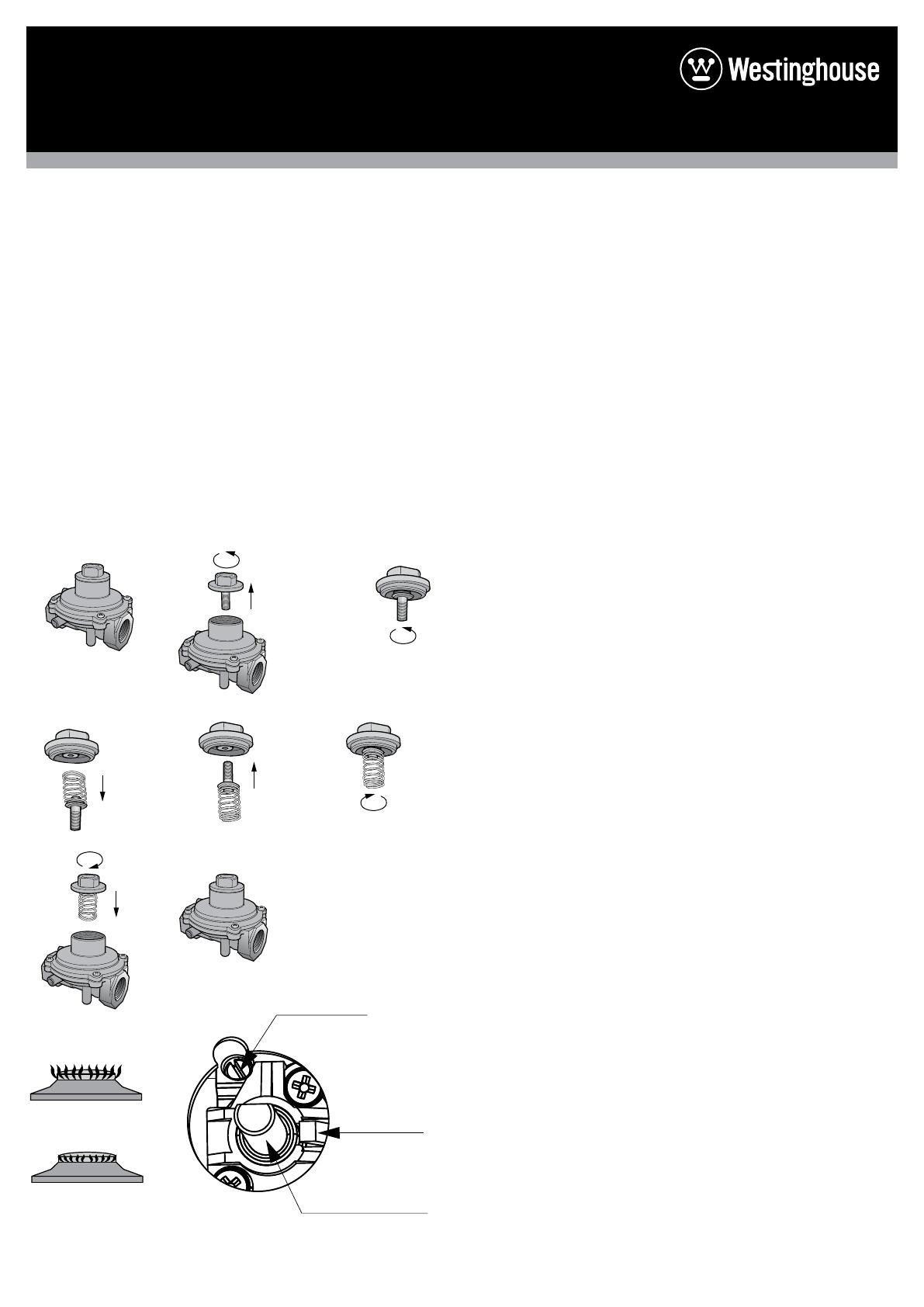
Flame size adjusted
to maximum
Flame size adjusted
to minimum
Bypass screw
Control knob shaft
Reposition
Top hat nut assembly,
fully screwed down
Turn top
hat nut anti-
clockwise
and remove
A B
H
D E
Configuration
for Natural Gas
C
Configuration for LPG
F
G
8
  • Page 1 1
  • Page 2 2
  • Page 3 3
  • Page 4 4
  • Page 5 5
  • Page 6 6
  • Page 7 7
  • Page 8 8

Westinghouse WFE916DSD Installation guide

Category
Cookers
Type
Installation guide
This manual is also suitable for

Westinghouse WFE916DSD features a spacious 90cm cooktop with gas burners that provide precise flame control for cooking a variety of dishes. The ceramic glass cooktop surface ensures even heat distribution and is easy to clean. The oven offers multiple cooking functions, including fan-forced cooking for even baking and roasting, and a separate grill function for grilling meats and vegetables. The separate grill function allows you to cook a variety of foods at the same time without compromising on taste or quality.

Ask a question and I''ll find the answer in the document

Finding information in a document is now easier with AI