Page is loading ...

Dell EMC Configuration and Deployment Guide
VCF on VxRail multirack deployment using BGP EVPN
Abstract
This document provides step-by-step deployment instructions for Dell
EMC OS10 L2 VXLAN tunnel using BGP EVPN. This guide provides the
foundation for multirack VxRail host discovery and deployment. Also, the
VMware Cloud Foundation (VCF) is deployed and provides a VMware
NSX environment to enable a Software Defined Data Center (SDDC).
June 2019

2 Dell EMC Configuration and Deployment Guide
Revisions
Date
Description
June 2019
Initial publication
The information in this publication is provided “as is.” Dell Inc. makes no representations or warranties of any kind with respect to the information in this
publication, and specifically disclaims implied warranties of merchantability or fitness for a particular purpose.
Use, copying, and distribution of any software described in this publication requires an applicable software license.
© 2019 Dell Inc. or its subsidiaries. All Rights Reserved. Dell, EMC, Dell EMC and other trademarks are trademarks of Dell Inc. or its subsidiaries. Other
trademarks may be trademarks of their respective owners.
Dell believes the information in this document is accurate as of its publication date. The information is subject to change without notice.

3 Dell EMC Configuration and Deployment Guide
Table of contents
Revisions............................................................................................................................................................................. 2
1 Introduction ................................................................................................................................................................... 6
1.1 Objective ............................................................................................................................................................. 7
1.2 VMware Software-Defined Data Center ............................................................................................................. 7
1.3 VMware Cloud Foundation on VxRail ................................................................................................................ 8
1.4 VMware Validated Design for SDDC on VxRail ................................................................................................. 9
1.5 Fabric Design Center ........................................................................................................................................ 10
1.6 Supported switches and operating systems ..................................................................................................... 11
1.7 Typographical conventions ............................................................................................................................... 12
1.8 Attachments ...................................................................................................................................................... 12
2 Physical infrastructure architecture ............................................................................................................................ 13
2.1 Hardware overview ........................................................................................................................................... 13
2.1.1 Dell EMC VxRail E560 ...................................................................................................................................... 13
2.1.2 Dell EMC VxRail P570 ...................................................................................................................................... 13
2.1.3 Dell EMC PowerSwitch S5248F-ON ................................................................................................................ 13
2.1.4 Dell EMC PowerSwitch S5232F-ON ................................................................................................................ 14
2.1.5 Dell EMC PowerSwitch Z9264F-ON................................................................................................................. 14
2.1.6 Dell EMC PowerSwitch S3048-ON................................................................................................................... 14
2.2 Network Transport ............................................................................................................................................ 15
2.2.1 Layer 3 leaf and spine topology ........................................................................................................................ 15
2.2.2 Border Gateway Protocol (BGP) Ethernet VPN (EVPN) .................................................................................. 15
2.2.3 EVPN instance and Autonomous System Number (ASN) considerations ....................................................... 17
2.2.4 VXLAN frame format Maximum Transmission Unit considerations ................................................................. 18
2.2.5 Routing in overlay networks ............................................................................................................................. 19
2.2.6 Leaf and Spine switch characteristics .............................................................................................................. 20
2.2.7 Underlay network physical design AZ1 ............................................................................................................ 21
2.3 Management domain architecture characteristics ............................................................................................ 22
3 Planning and Preparation for AZ1 .............................................................................................................................. 25
3.1 VLAN IDs and IP subnets ................................................................................................................................. 25
3.2 External Services .............................................................................................................................................. 25
3.2.1 DNS .................................................................................................................................................................. 26
3.2.2 NTP ................................................................................................................................................................... 26
3.2.3 DHCP ................................................................................................................................................................ 26
3.3 Switch settings .................................................................................................................................................. 27
3.3.1 Verify OS10 version .......................................................................................................................................... 28

4 Dell EMC Configuration and Deployment Guide
3.3.2 Verify license installation .................................................................................................................................. 28
3.3.3 Factory default configuration ............................................................................................................................ 29
4 Configure and verify the underlay network ................................................................................................................. 30
4.1 Configure the first leaf switch in AZ1 ................................................................................................................ 30
4.2 Configure the first spine switch in AZ1 ............................................................................................................. 38
4.3 Verify establishment of BGP between leaf and spine switches ....................................................................... 43
4.4 Verify BGP EVPN and VXLAN between leaf switches ..................................................................................... 44
5 Initialize the management VxRail cluster ................................................................................................................... 45
5.1 Configure laptop/workstation for VxRail initialization........................................................................................ 45
5.2 VxRail initialization ............................................................................................................................................ 46
5.3 VxRail deployment values ................................................................................................................................ 46
5.4 VxRail validation ............................................................................................................................................... 47
6 Deploy VMware Cloud Foundation for VxRail ............................................................................................................ 48
6.1 Configure first leaf switch for NSX VTEP traffic ............................................................................................... 48
6.2 Verify NSX VTEP DHCP IP addresses ............................................................................................................ 49
7 Configure Edge Service Gateways ............................................................................................................................ 50
7.1 Create a VM-Host affinity rule for ESGs ........................................................................................................... 51
7.2 Configure first leaf switch for north/south bound traffic .................................................................................... 52
7.3 Verify peering of NSX edge devices and establishment of BGP ...................................................................... 53
8 Stretching clusters to AZ2 .......................................................................................................................................... 54
8.1 Planning and Preparation ................................................................................................................................. 54
8.1.1 VLAN IDs and IP subnets for AZ2 .................................................................................................................... 54
8.1.2 vSAN witness traffic .......................................................................................................................................... 55
8.1.3 Underlay network physical design for AZ2 ....................................................................................................... 56
8.2 Configure and verify the underlay network ....................................................................................................... 57
8.2.1 More switch configurations in AZ1.................................................................................................................... 57
8.2.2 Switch settings for AZ2 ..................................................................................................................................... 58
8.2.3 Configure the first leaf switch in AZ2 ................................................................................................................ 60
8.2.4 Configure the first spine switch in AZ2 ............................................................................................................. 68
8.2.5 Verify establishment of BGP and EVPN between availability zones................................................................ 72
8.1 Next Steps ........................................................................................................................................................ 74
8.1.1 Expand the management cluster using the VxRail manager ........................................................................... 74
8.1.2 Deployment for multiple availability zones ....................................................................................................... 75
A Validated components ................................................................................................................................................ 76
A.1 Dell EMC PowerSwitch models ........................................................................................................................ 76
A.2 VxRail E560 and P570 nodes ........................................................................................................................... 76

5 Dell EMC Configuration and Deployment Guide
A.3 Appliance software ........................................................................................................................................... 77
B Technical resources ................................................................................................................................................... 78
B.1 VxRail, VCF, and VVD Guides ......................................................................................................................... 78
B.2 Dell EMC Networking Guides ........................................................................................................................... 78
C Support and feedback ................................................................................................................................................ 79

6 Dell EMC Configuration and Deployment Guide
1 Introduction
Our vision at Dell EMC is to be the essential infrastructure company from the edge, to the core, and to the
cloud. Dell EMC Networking ensures modernization for today’s applications and for the emerging cloud-native
world. Dell EMC is committed to disrupting the fundamental economics of the market with an open strategy
that gives you the freedom of choice for networking operating systems and top-tier merchant silicon. The Dell
EMC strategy enables business transformations that maximize the benefits of collaborative software and
standards-based hardware, including lowered costs, flexibility, freedom, and security. Dell EMC provides
further customer enablement through validated deployment guides which demonstrate these benefits while
maintaining a high standard of quality, consistency, and support.
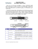
At the physical layer of a Software Defined Data Center (SDDC), the switching fabric can be provided by
either Layer 2 or Layer 3 transport services. A leaf-spine architecture using Layer 3 IP supports a scalable
data network. In a Layer 3 network fabric, the physical network configuration terminates Layer 2 networks at
the leaf switch pair at the top of each rack. However, VxRail node discovery and NSX Controller instances
and other virtual machines rely on VLAN-backed Layer 2 networks. Discovery or virtual machine migration
cannot be completed because the IP subnet is available only in the rack where the virtual machine resides.
One approach to solve this challenge is to implement Border Gateway Protocol (BGP) Ethernet VPN (EVPN)
to create control plane backed tunnels between the separate IP subnets creating Layer 2 networks that span
multiple racks or locations.
Layer 3 IP fabric
VXLAN overlay
VLAN
Spine 1
Z9264-ON
Spine 2
Z9264
-ON
VxRail Node
VxRail Node
Leaf 1A
S5248F-ON
Leaf 1B
S5248F-ON
Leaf 2A
S5248F-ON
Leaf 2B
S5248F-ON
L3
L2
Illustration of a stretched layer 2 segment between VxRail nodes

7 Dell EMC Configuration and Deployment Guide
smbiosDump | less
1.1 Objective
This guide is a supplement to the VMware Cloud Foundation on VxRail (VCF on VxRail) and VMware
Validated Design on VxRail 5.0 (VVD on VxRail 5.0) documentation. It aims to provide design guidance to
create a Layer 3 IP underlay with Layer 2 network overlays that enable the core services of the SDDC to
operate across separate subnets such as ESXi management, vMotion, and vSAN.
This example uses a typical leaf-spine topology with BGP EVPN as a control plane mechanism orchestrating
Virtual Extensible LANs (VXLANs) between the leaf switches. The individual switch configuration shows how
to set up an end-to-end IP underlay network using BGP with an end-to-end virtual network using BGP EVPN
L2 VXLAN configuration. The configuration provides a network virtual overlay (NVO) enabling east to west
traffic flows for the core services referenced.
Once the network components are in place, the initial components of a Standard SDDC are deployed using
VCF on VxRail. The deployment consists of a VVD management domain running on four Dell EMC VxRail E-
series nodes. These four nodes are equally distributed in two racks in Availability Zone 1 (AZ1) in the primary
data center (Region A). Using the network overlay for host discovery, both VxRail initialization tools and
VMware Cloud Builder are used to complete the installation of the software components of the SDDC.
To accommodate north and southbound traffic into the SDDC, a pair of Equal-cost multi-path (ECMP)-
enabled VMware NSX Edge Services Gateways (ESGs) are deployed. Using VM/host affinity rules, the ESGs
are restricted to a single rack, enabling it as the edge rack, and BGP is configured between these ESGs and
the leaf switches in the designated edge rack. In this example, WAN connectivity into the fabric is established
between the spine switches and the data center core.
To provide site resiliency, a second availability zone (AZ2) is created and has connectivity to AZ1 through a
Data Center Interconnection (DCI). The DCI is established between spine switches in both availability zones.
VMware vSAN stretched clusters are established with the vSAN witness appliance located in Region B and
are reachable through the DCI. Additional NSX components, including ESGs, are deployed in AZ2 and
connected in a similar manner to AZ1.
Note: For more information about VCF on VxRail, see Dell EMC VxRail Hyperconverged Infrastructure
.
1.2 VMware Software-Defined Data Center
The VMware vision of the modern data center starts with a foundation of software-defined infrastructure. The
foundation is based on the value that customers realize from a standardized architecture. It is a fully
integrated hardware and software stack that is simple to manage, monitor, and operate. The VMware
approach to the software-defined data center, or SDDC, delivers a unified platform that supports any
application and provides flexible control. The VMware architecture for the SDDC enables companies to run
private and hybrid clouds. The architecture uses unique capabilities to deliver key outcomes that enable
efficiency, agility, and security.
The fully virtualized data center is automated and managed by intelligent, policy-based data center
management software, vastly simplifying governance and operations. A unified management platform enables
centralized monitoring and administration of all applications across physical geographies, heterogeneous
infrastructure, and hybrid clouds. Workloads can be deployed and managed in physical, virtual, and cloud
environments with a unified management experience. IT becomes agile, elastic, and responsive to a degree
never before possible.

8 Dell EMC Configuration and Deployment Guide
The VMware SDDC is based on well-established products from VMware. vSphere, vSAN and NSX provide
compute, storage and networking virtualization to the SDDC and the vRealize Suite brings additional
management, self-service, automation, intelligent operations and financial transparency. These VMware
products form a solid foundation to host both traditional and cloud-native application workloads.
VMware software-defined data center high-level architecture
Note: To learn more about VMware SDDC, see Dell EMC VxRail - Accelerating the Journey to VMware
Software-Defined Data Center (SDDC).
1.3 VMware Cloud Foundation on VxRail
VMware Cloud Foundation (VCF) on VxRail is a new Dell EMC flagship offering for VMware SDDC. VCF
builds upon native VxRail and Cloud Foundation capabilities with more unique Dell EMC and VMware jointly
engineered integration features. These features simplify, streamline, and automate the operations of your
entire SDDC from Day 0 through Day 2 operations.
VCF on VxRail provides the simplest path to the hybrid cloud through a fully integrated hybrid cloud platform.
VCF on VxRail uses native VxRail hardware and software capabilities, and other VxRail unique integrations.
vCenter plugins and Dell EMC networking integration work together to deliver a turnkey hybrid cloud user
experience with full stack integration. Full stack integration means customers get an HCI infrastructure layer
and cloud software stack in one, complete, automated life cycle, turnkey experience. The new platform
delivers software defined services for compute using vSphere and vCenter, storage using vSAN, networking
using NSX, and security and cloud management using vRealize Suite in both private or public environments.
The services make it the operational hub for their hybrid cloud.
VCF on VxRail simplifies the data center by automating the public cloud in-house, and by deploying a
standardized and validated network flexible architecture with integrated life cycle automation for the entire
cloud infrastructure stack including hardware. SDDC Manager orchestrates the deployment, configuration,
and life cycle management (LCM) of vCenter, NSX, and vRealize Suite above the ESXi and vSAN layers of
VxRail. It unifies multiple VxRail clusters as workload domains or as multicluster workload domains.

9 Dell EMC Configuration and Deployment Guide
Integrated with the SDDC Manager management experience, VxRail Manager is used to deploy and
configure vSphere clusters that are powered by vSAN. It is also used to run the life cycle management of
ESXi, vSAN, and hardware firmware using a fully integrated and unified SDDC Manager orchestrated
process. It monitors the health of hardware components and provides remote service support as well. This
level of integration is what gives customers a truly unique turnkey hybrid cloud experience not available on
any other infrastructure.
VMware Cloud Foundation on VxRail (VCF on VxRail) high-level architecture
To learn more about VMware Cloud Foundation on VxRail, see:
VMware Cloud Foundation on VxRail Administrator Guide
VMware Cloud Foundation on VxRail Planning and Preparation Guide
1.4 VMware Validated Design for SDDC on VxRail
VMware Validated Designs (VVD) simplify the process of deploying and operating an SDDC. They are
comprehensive, solution-oriented designs that provide a consistent and repeatable production-ready
approach to the SDDC. By definition, they are prescriptive blueprints that include comprehensive deployment
and operational practices for the SDDC. It is an option available for customers, who are not ready or not value
a complete approach to SDDC automation available in VCF on VxRail.
A VMware Validated Design is composed of a standardized, scalable architecture that is backed by the
technical expertise of VMware and a software bill of materials (BOM) comprehensively tested for integration

10 Dell EMC Configuration and Deployment Guide
and interoperability that spans compute, storage, networking, and management. Detailed guidance that
synthetizes best practices on how to deploy, integrate, and operate the SDDC is provided to aid users to
achieve performance, availability, security, and operational efficiency.
With the VVD for SDDC on VxRail, customers can easily architect, implement, and operate the complete
SDDC faster and with less risk. Customers also get the benefits of best of breed HCI infrastructure platform.
The latest available version at the time of writing this document is 5.0.
Customers can realize the following benefits by using VVD on VxRail:
• Accelerated time-to-market - streamline and simplify the complex design process of the SDDC,
shortening deployment and provisioning cycles
• Increased efficiency – provide detailed, step-by-step guidance to reduce the time and the effort
that is spent on operational tasks
• Lessen the uncertainty of deployments and operations - reduce uncertainty and potential risks
that are associated with implementing and operating the SDDC
• IT agility – designed for expandability and to support a broad set of use cases and diverse types
of applications that helps IT respond faster to the business needs
To learn more about VVD on VxRail, see
Dell EMC VxRail - Accelerating the Journey to VMware Software-
Defined Data Center (SDDC).
1.5 Fabric Design Center
The Dell EMC Fabric Design Center (FDC) is a cloud-based application that automates the planning, design,
and deployment of network fabrics that power Dell EMC compute, storage, and hyper-converged
infrastructure solutions, including VxRail. The FDC is ideal for turnkey solutions and automation that is based
on validated deployment guides like this one.
FDC enables design customization and flexibility to go beyond validated deployment guides. For additional
information, see the Dell EMC Fabric Design Center
.

11 Dell EMC Configuration and Deployment Guide
1.6 Supported switches and operating systems
The examples provided in this Deployment Guide use VxRail 4.7.111 nodes that are connected to Dell EMC
PowerSwitch S5248F-ON switches running the Dell EMC OS10 Enterprise Edition (OS10EE) 10.4.3.1. Any
Dell PowerSwitch device can work but must be running OS10EE 10.4.3.1 or later to take advantage of NVO
technologies referenced in this paper.
Dell EMC Networking supports the following switch and OS combinations for VxRail 4.7.111 and later using
NVO technologies:
Supported Dell EMC Networking switches and operating systems

12 Dell EMC Configuration and Deployment Guide
1.7 Typographical conventions
The CLI and GUI examples in this document use the following conventions:
Monospace Text CLI examples
Underlined Monospace Text CLI examples that wrap the page
Italic Monospace Text Variables in CLI examples
Bold Monospace Text Commands entered at the CLI prompt, or to highlight information in CLI
output
Bold text GUI fields and information entered in the GUI
1.8 Attachments
This document includes switch configuration file attachments. To access attachments in Adobe Acrobat
Reader, click the icon in the left pane halfway down the page, then click the icon.

13 Dell EMC Configuration and Deployment Guide
2 Physical infrastructure architecture
The architecture of the data center physical layer is based on logical hardware domains and the physical
network topology. This section provides guidance on the hardware that is used as well as providing a general
understanding of the physical network and the networking protocols used.
2.1 Hardware overview
This section provides an overview of the hardware that is used to validate this deployment. Appendix A
contains a complete listing of hardware and software that is validated for this guide.
2.1.1 Dell EMC VxRail E560
The Dell EMC VxRail E series consists of nodes that are best suited for remote office or entry workloads. The
E series nodes support up to 40 CPU cores, 1536GB memory, and 16TB hybrid or 30TB all-flash storage in a
1-Rack Unit (RU) form factor. The example within this document uses four VxRail E560 nodes, located in
Region A, AZ1, and is part of the management cluster.
Dell EMC VxRail 1-RU node
2.1.2 Dell EMC VxRail P570
The Dell EMC VxRail P series consists of high-performance nodes that are optimized for heavy workloads,
such as databases. Each appliance in the series has one node per 2-RU chassis. The models within this
series are the Dell EMC VxRail P570 (hybrid), and the Dell EMC VxRail P570F (all-flash). The example within
this document uses four VxRail P570 nodes, located in Region A, AZ2, and is part of the management
cluster.
Dell EMC VxRail 2-RU node
2.1.3 Dell EMC PowerSwitch S5248F-ON
The Dell EMC PowerSwitch S5248F-ON is a 1-RU fixed switch with 48x 25 GbE, 4x multirate 100 GbE, and
2x 200 GbE ports. The S5248F-ON supports L2 static VXLAN with VLT. The example within this document
uses eight S5248F-ON switches in VLT pairs as leaf switches. There are four pairs total, two in AZ1 and two
in AZ2.
Dell EMC PowerSwitch S5248F-ON

14 Dell EMC Configuration and Deployment Guide
2.1.4 Dell EMC PowerSwitch S5232F-ON
The Dell EMC PowerSwitch S5232F-ON is a 1-RU fixed switch with 32x 100 GbE and 2x10 GbE ports. The
S5232F-ON is part of the S5200-ON series of switches. The example within this document uses two S5232F-
ON switches as spine switches in Region A, AZ2.
Dell EMC PowerSwitch S5232F-ON
2.1.5 Dell EMC PowerSwitch Z9264F-ON
The Dell EMC PowerSwitch Z9264F-ON is a 2-RU 100 GbE aggregation/spine switch. The Z9264F-ON has
up to 64 ports of multirate 100 GbE, or up to 128 ports of 10/25/40/50 GbE ports using supported breakout
cables. The example within this document uses two Z9264F-ON switches as spine switches in Region A,
AZ1.
Dell EMC PowerSwitch Z9264F-ON
Note: Either the Dell EMC PowerSwitch S5232F-ON or the Z9264F-ON can be used as spine switches for
either or both environments. A combination was used in this document to illustrate the capabilities of both
platforms.
2.1.6 Dell EMC PowerSwitch S3048-ON
The Dell EMC PowerSwitch S3048-ON is a 1-RU switch with 48x1GbE BASE-T ports and 4x 10GbE SFP+
ports. This guide uses one S3048-ON switch for out-of-band (OoB) management traffic.
Dell EMC PowerSwitch S3048-ON

15 Dell EMC Configuration and Deployment Guide
2.2 Network Transport
VMware Validated Design supports both Layer 2 and Layer 3 transports. In this section, the details of the
Layer 3 leaf-spine topology are provided.
2.2.1 Layer 3 leaf and spine topology
In this document, a Clos leaf-spine topology is used for each availability zone. Individual switch configuration
shows how to set up end-to-end Virtual Extensible Local Area Networks (VXLANs). External Borer Gateway
Protocol (eBGP) is used for exchanging IP routes in the IP underlay network, and EVPN routes in the VXLAN
overlay network. Virtual Link Trunking (VLT) is deployed between leaf pairs and internal BGP (iBGP) to
provide Layer 3 path redundancy in the event a leaf switch loses connectivity to the spine switches.
Layer 3 IP fabric
Spine 1
Z9264-ON
Spine 2
Z9264
-ON
Leaf 1A
S5248F-ON
Leaf 1B
S5248F-ON
Leaf 2A
S5248F-ON
Leaf 2B
S5248F-ON
L3
L2
Layer 3 IP network transport
Note: For detailed instructions on creating a leaf-spine underlay, including considerations and alternative
configurations, see Dell EMC Networking Layer 3 Leaf-Spine Deployment and Best Practices with OS10EE.
2.2.2 Border Gateway Protocol (BGP) Ethernet VPN (EVPN)
EVPN is a control plane for VXLAN tunnels over a Layer 3 infrastructure such as a leaf-spine network. EVPN
is used to reduce flooding in the network and resolve scalability concerns when compared against Static
VXLAN. EVPN uses multiprotocol BGP (MP-BGP) to exchange information between Virtual Tunnel Endpoints
(VTEPs). EVPN was introduced in RFC 7432 and is based on BGP MPLS VPNs. RFC 8365 describes
VXLAN-based EVPN.
The MP-BGP EVPN control plane provides protocol-based remote VTEP discovery, and MAC and ARP
learning. As a result, flooding related to L2 unknown unicast traffic is reduced. The distribution of host MAC
and IP reachability information supports virtual machine mobility and scalable VXLAN overlay network
designs.
The BGP EVPN protocol groups MAC addresses and ARP/neighbor addresses under EVPN instances (EVIs)
to exchange them between VTEPs. In OS10EE, each Virtual Network Interface (VNI) is mapped using switch
scoped assignments where each VLAN is associated with a VNI in a 1:1 mapping. The benefits for deploying
a BGP EVPN for VXLAN topology include:
• Eliminates the flood-and-learn method of VTEP discovery by enabling control-plane learning of
end-host Layer 2 and Layer 3 reachability information
• Minimizes the network flooding of unknown unicast and broadcast traffic through EVPN-based
MAC and IP route advertisements on local VTEPs
• Supports host mobility
OS10EE supports two types of VXLAN Network Virtual Overlay (NVO) networks:

16 Dell EMC Configuration and Deployment Guide
• Static VXLAN
• BGP EVPN
Static VXLAN and BGP EVPN for VXLAN are configured and operate in the same ways:
• The overlay and underlay networks are manually configured
• Each virtual network and VNI are manually configured
• Access port membership in a virtual network is manually configured
• Underlay reachability to VTEPs peers is provisioned or learned using existing routing protocols
Static VXLAN and BGP EVPN for VXLAN configuration and operation differ as described in Table 1.
Differences between Static VXLAN and VXLAN BGP EVPN
Static VXLAN
BGP EVPN for VXLAN
To start sending and receiving virtual-network
traffic to and from a remote VTEP, manual
configuration of VTEP must be completed.
No manual configuration is required. Each remote VTEP
is automatically learned as a member of a virtual network
from the EVPN routes received from the remote VTEP.
After a remote VTEP’s address is learned, VXLAN traffic
is sent to, and received from, the VTEP.
Remote hosts are learned from data packets
after decapsulation of the VXLAN header in
the data plane.
Remote host MAC addresses are learned in the control
plane using BGP EVPN Type 2 routes and MAC/IP
advertisements
Note: For more information about static L2 VXLAN configuration, see
Dell EMC VxRail Multirack Deployment
Guide.
In this guide, BGP EVPN is used to create virtual networks to handle all the VxRail specific VLANs to create a
management domain. This includes VMware ESXi management, vMotion, vSAN, and node discovery.
Additionally, external services are in a separate virtual network to highlight the capabilities of Routing in and
Out of Tunnels (RIOT).
All VMware NSX traffic, including NSX VTEPs and ESG traffic, is handled by traditional networking concepts
and routed through the default VRF.
Terminology
• VXLAN (Virtual Extensible LAN) - The technology that provides the same Ethernet Layer 2
network services as VLAN does today, but with greater extensibility and flexibility
• VNID (VXLAN Network Identifier) - 24 bit segment ID that defines the broadcast domain.
• VTEP (Virtual Tunnel Endpoint) - This is the device that does the encapsulation and de-
encapsulation
• NVE (Network Virtual Interface) - Logical interface where the encapsulation and de-
encapsulation occur

17 Dell EMC Configuration and Deployment Guide
2.2.3 EVPN instance and Autonomous System Number (ASN) considerations
An EVPN instance (EVI) spans across the VTEPs that participate in an EVPN. Each virtual network, or tenant
segment, that is advertised using EVPN must be associated with an EVI. In OS10, configure EVIs in auto-EVI
or manual configuration mode.
Auto-EVI configuration mode
When a virtual network is associated with a VTEP, auto-EVI mode automatically creates an EVPN instance.
Auto EVI mode does the following:
• The EVI ID auto-generates with the same value as the virtual-network ID (VNID) configured on
the VTEP and associates with the VXLAN network ID (VNI)
• A route distinguisher (RD) auto-generates for each EVI ID. An RD maintains the uniqueness of an
EVPN route between different EVPN instances.
• A Route Target (RT) import and export auto-generates for each EVI ID. A RT determines how
EVPN routes are distributed among EVPN instances.
Manual EVI configuration mode
To specify the RD and RT values, manually configure EVPN instances and associate each EVI with the
overlay virtual network using the VXLAN VNI. The EVI activates only when the virtual network, RD, and RT
values are configured.
Route distinguisher
A RD is an 8-byte identifier that uniquely identifies an EVI. Each EVPN route is prefixed with a unique RD and
exchanged between BGP peers, making the tenant route unique across the network. In this way, overlapping
address spaces among tenants are supported.
Route target
While the RD maintains the uniqueness of an EVPN route among different EVIs, an RT controls the way the
EVPN routes are distributed among EVIs. Each EVI is configured with an import and export RT value. BGP
EVPN routes advertise for an EVI and carry the export RT associated with the EVI. A receiving VTEP
downloads information in the BGP EVPN route to EVIs that have a matching import RT value.
Autonomous System Number (ASN)
In this document, manual EVI configuration mode is used to ensure that ASN values are different between
leaf switches participating in the same virtual networks. In this document, each leaf pair is associated with a
unique ASN value regardless of the availability zone. Figure 12 shows the ASN values used in AZ1 and AZ2
will use different values. Using manual EVI lends itself to a brownfield environment where the ASN values
have already been established.

18 Dell EMC Configuration and Deployment Guide
ASN 65102
ASN 65101
ASN 65100
Leaf 1A
S5248F-ON
Leaf 1B
S5248F-ON
Leaf 2A
S5248F-ON
Leaf 2B
S5248F-ON
Spine 1
Z9264-ON
Spine 2
Z9264-ON
ASN values in AZ1
Note: In this example, private AS 2-byte values are used, and these should be changed to reflect the AS
numbers and needs used in the environment. For example, in the Dell EMC Networking Layer 3 Leaf-Spine
Deployment and Best Practices with OS10EE guide separate AS numbers are used for each spine switch,
both models are accessible.
2.2.4 VXLAN frame format Maximum Transmission Unit considerations
VXLAN allows a Layer 2 network to scale across the data center by overlaying an existing Layer 3 network
and is described in Internet Engineering Task Force document RFC 7348. Each overlay is referred to as a
VXLAN segment.
Each segment is identified through a 24-bit segment ID referred to as a VNI. This allows up to 16 Million VNIs,
far more than the traditional 4,094 VLAN IDs allowed on a physical switch.
VXLAN is a tunneling scheme that encapsulates Layer 2 frames in User Datagram Protocol (UDP) segments,
as shown in Figure 13.
VXLAN encapsulated frame
VXLAN encapsulation adds approximately 50 bytes of overhead to each Ethernet frame. As a result, all
switches in the underlay (physical) network must be configured to support an MTU of at least 1600 bcytes on
all participating interfaces.

19 Dell EMC Configuration and Deployment Guide
2.2.5 Routing in overlay networks
Integrated routing and bridging (IRB)
With EVPN, overlay routing occurs on leaf switches. As of OS10EE version 10.4.3.1, Dell EMC
PowerSwitches support asymmetric IRB. This means that overlay routing, also known as RIOT, occurs on
ingress leaf switches. The packets travel over the leaf and spine network on the destination VNI. When the
packets arrive at the destination VTEP, they are bridged to the endpoint.
Anycast gateway
Anycast gateways with the same IP address are deployed to each leaf pair connected to servers. The anycast
gateway IP address is set as the default gateway for all VMs on that virtual network. VMs on VNIs with
anycast gateways use the same gateway information while behind different leaf pairs. When those VMs
communicate with different networks, their local leaf switches always do the routing. This replaces Virtual
Router Redundancy Protocol (VRRP) and enables VMs to migrate from one leaf pair to another without the
need to change the network configuration.
Indirect gateway
As shown in Figure 6, VNI C does not have an anycast gateway configured. It uses an indirect gateway
attached to the border leafs instead. In this case, the indirect gateway is a physical switch acting as a
firewall/gateway to the Internet. When a VM on VNI C sends a packet destined for another network, it is
tunneled to the border leaf pair where it is forwarded to the indirect gateway which makes the proper
forwarding decisions according to its routing table.
In this deployment example, all VNIs use the anycast gateway model to provide IP reachability between both
availability zones and Region B. While not discussed in this document, the indirect gateway model would be
used to route any VNI to Internet.
WAN
AZ2
Spines
VxRail
Nod e
VxRail
Nod e
VxRail
Nod e
VxRail
Nod e
Leaf
Switches
AZ1
Spines
Leaf
Switches
Region B
(vSAN witness)
Layer 3
DCI
VTE P VTE P
Name L ocation VLAN
Management
vSA N
Discovery
vMotion
AZ1/AZ2
RegionB
AZ1/AZ2
RegionB
AZ1/AZ2
AZ1/AZ2
1611
1711
1613
1713
3939
1612
VTE P
Distributed routing

20 Dell EMC Configuration and Deployment Guide
2.2.6 Leaf and Spine switch characteristics
The leaf switches act as the VXLAN tunnel endpoints and perform VXLAN encapsulation and decapsulation.
The leaf switches also participate in the MP-BGP EVPN to support control plane and data plane functions.
The control plane functions include:
• Initiate and maintain route adjacencies using any routing protocol in the underlay network
• Advertise locally learned routes to all MP-BGP EVPN peers
• Process the routes received from remote MP-BGP EVPN peers and install them in the local
forwarding plane
The data plane functions include:
• Encapsulate server traffic with VXLAN headers and forward the packets in the underlay network
• Decapsulate VXLAN packets received from remote VTEPs and forward the native packets to
downstream hosts
• Perform underlay route processing, including routing based on the outer IP address
The role of the spine switch changes based on its control plane and data plane functions. Spine switches
participate in underlay route processing to forward packets and in the overlay network to advertise EVPN
routes to all MP-BGP peers.
The control plane functions include:
• Initiate BGP peering with all neighbor leaf switches
• Advertise BGP routes to all BGP peers
• In the underlay network, initiate and maintain the routing adjacencies with all leaf and spine
switches
The data plane functions include:
• Perform only the underlay route processing based on the outer header in VXLAN encapsulated
packets
• Does not perform VXLAN encapsulation or decapsulation
/