
Instructional Leaet P26841
Effective August 2014
Supersedes July 2014
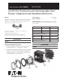
Contact
Blocks
2
1
Adapter
Locating
Nib
Operator
Ratings
Hazardous Location Class I Division 2 pushbuttons and indicat-
ing lights include both the 10250T and E34 corrosion-resistant
product lines. The 10250T1H (CBFS) factory-sealed contact
blocks have one NO and one NC contact.
For use on a at surface of Type 1, 2, 3, 3S*, 3R, 4, 4X,
12 and 13 enclosures.
* Applies to indicating lights only.
UL Listed and CSA Certied for Class I Division 2
Groups B, C, D, and Class I Zone 2, Group IIB + H2.
WARNING
A LENS MUST BE ATTACHED TO ALL ILLUMINATED
DEVICES
10250T/E34 Pushbuttons and Indicating Lights Class I
Division 2 Application and Installation Instructions
Contact Ratings ............................................. A600, Q300
Ingress Protection ..................................................... IP65
Temperature Codes per NEC Table 500-5(d) for indicating
lights and illuminated operators having a maximum tempera-
ture over 100°C:
10250T E34 Temp. code
201H RB120H T3C
471H SB120H T3C
80H - T3C
All selector switches with lamp 120MB T3C
202H RB240H T3A
472H SB240H T3B
81H - T3B
All illuminated devices with lamp 1835 T4A
WARNING
TOUT DISPOSITIF LUMINEUX DOIT COMPORTER UNE
LENTILLE
Operator And Adapter Assembly
1. Assemble adapter to operator or light unit and torque
mounting screws to 7 – 9.5 lb-in (0.8 – 1.07 Nm).
2. Assemble contact block to adapter and torque mounting
screws to 12 – 16 lb-in (1.36 – 1.81 Nm). Contact block
mounting location “1” is referenced to the panel locat-
ing nib on operator. See illustrations.
®
IND. CONT. EQ.
FOR HAZARDOUS
LOCATIONS.
A162
®

2
Instructional Leaet P26841
Effective July 2014
10250T/E34 Pushbuttons
And Indicating Lights
EATON www.eaton.com
EATON www.eaton.com
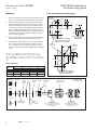
Mounting
1. Drill mounting hole for vertical or horizontal mount-
ing per the matrix below and diagram to the right.
2. Ensure sealing gasket is in place on the operator.
Align locating nib on operator with notch in panel
and insert through mounting hole. If notched hole
is not desired, remove locating nib by placing a flat
head screwdriver between nib and operator and
prying outward. Note: When using protective boots,
see special instruction publication 20437 for place-
ment of sealing gasket.
3. Place legend plate and mounting nut over operator.
Tighten mounting nut securely (5 lb-ft / 6.8 Nm).
4. If applicable, assemble lenses, mushroom buttons,
etc. to operator. Tighten selector switch set screw
to 8 – 12 lb-in (0.9 – 1.35 Nm). Note: Ensure lens is
securely tightened to provide oiltight and watertight
seal.
For ease of assembly, the following tools are recom-
mended: 10250TA95 or E22CW for tighening octagonal
nuts. 10250TA74 — lamp removal tool for transformertype
light units. E30KV1 — lamp removal tool for full voltage light
units.
Mounting Matrix
Panel Spacing And Drilling Drawings
Nameplate
Retaining Nut
5 lb-ft (6.8 Nm)
Panel
1/16" – 1/4"
(1.5 – 6.5 mm)
Thrust
Washer
(Optional)
Lens
Washer
Illuminated
Pushbutton
Indicator
Light
Push/Pull
Light Unit
Lamp
E34 Earth
Terminal
Operator
Gasket
Operator
Terminal Clamp:
One or Two Copper Conductors
22 – 12 AWG (0.34 – 4.0 mm
2
)
7 lb-in (0.8 Nm)
Contact Block
Mounting Adapter
RATINGS ARE STAMPED
ON LIGHT UNIT
AND CONTACT BLOCK
Terminal Clamp:
Single Copper Conductor
18 – 14 AWG (.75 – 2.5 mm
2
)
9 lb-in (1.0 Nm)
Contact Block
.19
(5.0)
.67
(17.0)
ø1.2
(ø30.5)
“D” Min.
“C” Min.
Terminals for
Light Unit
.60
(15.2)
ø.14
(ø3.4)
ø1.2
(ø30.5)
“B” Min.
“A” Min.
Terminals for
Light Unit
Notch for
Locating Nib
Drilling for One Hole Mounting
and Dimensions for Minimum
Spacing in Vertical Rows.
Drilling for One Hole Mounting
and Dimensions for Minimum
Spacing in Horizontal Rows.
NOTE: Suitable for Use
in This Alternate
Mounting Hole.
Legend Dimensions in Inches (mm)
Plate ABCD
Small 72.6 (2.87) 57.2 (2.25) 57.2 (2.25) 72.6 (2.87)
Jumbo 72.6 (2.87) 58.6 (2.32) 58.6 (2.32) 72.6 (2.87)
Extra Large 72.6 (2.87) 65.2 (2.56) 64.1 (2.52) 72.6 (2.87)

3
10250T/E34 Pushbuttons
And Indicating Lights
Instructional Leaet P26841
Effective July 2014
EATON www.eaton.com
EATON www.eaton.com
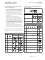
Selector Switch Selection And Assembly — Refer To
Contact Block Selection Charts
1. Select intended schematic circuit function. Note in
your “cam” column the type of contact (NO or NC),
the “1” and “2” circuit locations, and any series or
parallel jumper connections that may be required.
2. Choose contact blocks that have the required
schematic circuits and assemble in any convenient
sequence that fulfills the “1” and “2” circuit location
requirements.
3. If applicable, assemble the operator cap.
Recommended, set screw tightening torque for
selector switches is 8 – 12 lb-in (0.9 – 1.35 Nm).
4. The two sections of the operating cam work indepe-
ndently. It is important that the contact blocks be
oriented with their plungers in the correct “1” and
“2” circuit locations. The drawing to the right identi-
fies these positions with respect to the locating nib
on operator or marked top.
5. Assembled operators are factory set for Vertical
Mounting. For Horizontal Mounting, loosen the set
screw and assemble with the locating nib on the left.
ote:N Circuits shown illustrate connections to obtain a selector
circuit combination and are shown with their appropriate line dia-
grams in BOLD. Field wiring of jumper connections are required
as shown.
Mounting Location Of Contact Blocks With Respect To
Operator Locating Nib.
2-Position Selector Switch
Number Desired Circuit and Cam Code #1
Operator Position
Contact Blocks and
Mounting Location
1 2
1 X O
2 O X
4-Position Selector Switch
No. Desired Circuit and Operator Position Cam Code #7
Contact Blocks and
Mounting Location
1 2
1 X OOO
2 O X O O
3 O O X O
4 OOO X
5 X O O X
6 O X X O
7 O O X X
8 X X O O
9 O X O X
10 X O X O
NC NC
NO NO
or
or
NC
NO
NO
NC
NC (Parallel) NC
NO (Parallel) NO
NO (Parallel) NC
NC (Parallel) NO
NO/NC
(Parallel)
NO/NC
(Parallel)
Locating Nib
1 2
tiucriC nepO = OtiucriC desolC = X
3-Position Selector Switch
No. Desired Circuit and Cam Code #2 Cam Code #3
Operator Position
Contact Blocks and Contact Blocks and
Mounting Location Mounting Location
1 2 1 2
1 X O O
2 X X O
3 X O X
4 O O X
5 O X X
6 O X O
NO (Series) NC NO
NC NC
NO NO (Parallel) NO
NO NO
NC (Parallel) NO NC
NC NC (Series) NC

Instructional Leaet P26841
Effective July 2014
10250T/E34 Pushbuttons
And Indicating Lights
Eaton
1000 Eaton Boulevard
Cleveland, OH 44122
United States
Eaton.com
© 1999 Eaton
All Rights Reserved
Publication No. P26841 / 004
August 2014
Eaton is a registered trademark.
All other trademarks are property
of their respective owners.
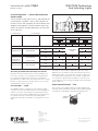
nepO tcatnoC = OdesolC tcatnoC = X
tnemegnarrA tiucriC dna noitisoP rotarepOkcolB tcatnoCrebmuN golataCrotarepO fo epyT
Out — Pull Intermediate In — Push
Contact Block Mounting Location
121212
2-Position Operator without Lens
XXOOONI
Maintained Push-Pull 10250T5/E34GDB
OOXXCNI
XXOOON2
OOXXCN2
3-Position Operator without Lens
Momentary Push-Pull 10250T4/E34GEB
1NO OOOO X O
1NC X X O X O O
Maintained Push-
10250T9/E34GFB
2NO OOOO X O
OOXOXXCN2lluP yratnemoM
1NO OOOO X X
Momentary Push-Pull 10250T10/E34GHB
1NC X X OOOO
2NO OOOO X X
2NC X X OOOO
or
No Intermediate
Position
or
or
or
or
or or
or
Push-Pull Operators — Contact Block Selection
And Assembly
The illustration to the right assists in the selection of
contact blocks. Symbols 1 and 2 show locations of
contact circuits after assembly of contact blocks and
adapter to the operator. The chart below shows the
effects of the push and pull operations on either NO
or NC contacts.
Grounding Of 10250T And E34 Components General
With any electrical component there is the possibility of a
loose wire, moisture, etc. causing a short circuit between
the component and ground. If the device is adequately
grounded, the condition causes the protective fuse or circuit
breaker to open and remove the potential. If not, an electri-
cal hazard may remain unnoticed.
Grounding Nibs — 10250T
The 10250T operator is designed to make direct metallic
contact to the rear of the panel (with no intervening spacer
washers to interfere with component-to-panel ground con-
tinuity). As a further aid in establishing an electrical ground,
the operator has four metal points (“grounding nibs”)
designed to penetrate most paints or other protective coat-
ings.
Penetration of these nibs is dependent upon the torque
applied to the mounting nut. Recommended torque is 5 ft-
lbs (6.8 Nm). More or less may be necessary to penetrate
the specific type and thickness of your panel coating. Test
for continuity to ground after installation. If a short circuit
to ground does occur, the fault should be corrected and the
device replaced.
Earth Ground Terminals — E34
These devices are supplied with an integral earth/ground
terminal. A 6-32 terminal screw will accommodate ring type
terminations for bonding to international specifications.
Locating Nib
1 2
Earth
Terminal
Nibs
-
 1
1
-
 2
2
-
 3
3
-
 4
4


Ask a question and I''ll find the answer in the document
Finding information in a document is now easier with AI
Related papers
-
Eaton Nema pushbuttons 10250T contact block Owner's manual
-
-
-
Eaton Series NRX low voltage power air circuit breakers User manual
-
-
-
-
Eaton C361 User manual
-
-
Other documents
-
Unbranded T3C-24-MV-30 Installation guide
-
IDEC AVS301N-R Operating instructions
-
Weider XT1 User manual
-
Schneider Electric 9001AB1 Specification
-
ZyXEL P-202H User manual
-
Emerson Unicode 2 Control Stations Switches Quick start guide
-
-
Eaton Electrical Cutler-Hammer CA03310002E User manual
-
Honeywell MICRO SWITCH GLL Series Installation guide
-
Zest 4 Leisure Cheltenham Arbour with Storage Box Assembly Instructions Manual