Gigabyte GA-8I955X Royal User manual

Category
Peripheral controllers
Type
User manual

The Gigabyte GA-8I955X Royal motherboard boasts cutting-edge features for an exceptional computing experience. With its Intel 955X Express Chipset and support for the latest LGA775 CPUs, including Core 2 Duo and Core 2 Quad processors, this motherboard unleashes powerful performance for demanding applications and multitasking. It also features DDR2 memory technology, delivering faster data transfer speeds and enhanced system responsiveness.

The Gigabyte GA-8I955X Royal motherboard boasts cutting-edge features for an exceptional computing experience. With its Intel 955X Express Chipset and support for the latest LGA775 CPUs, including Core 2 Duo and Core 2 Quad processors, this motherboard unleashes powerful performance for demanding applications and multitasking. It also features DDR2 memory technology, delivering faster data transfer speeds and enhanced system responsiveness.

SATA RAID Function
(Only for chipset Sil3132 used)
User’s Manual
12ME-SI3132-001
SATARAID5 User’s Manual
2
Table of Contents
1 WELCOME .........................................................................................................................................................4
1.1 SATARAID5 FEATURES .................................................................................................................................4
2 AN INTRODUCTION TO RAID........................................................................................................................5
2.1 DISK STRIPING (RAID 0) ....................................................................................................................................5
2.2 DISK MIRRORING (RAID 1)................................................................................................................................5
2.3 CONCATENTION .............................................................................................................................................5
3 INSTALLING DRIVERS ...................................................................................................................................6
4 JAVA 2 RUNTIME ENVIRONMENT INSTALLATION..............................................................................7
5 SATARAID5 GUI INSTALLATION ................................................................................................................9
6 CREATING AND DELETING LEGACY RAID GROUPS WITH BIOS UTILITY.................................10
6.1 CREATING RAID GROUPS.............................................................................................................................12
6.2 CREATING SPARE DRIVE...............................................................................................................................13
6.3 CREATING CONCATENATION..................................................................................................................13
6.4 DELETING RAID GROUPS, SPARE DRIVE, AND CONCATENATION.............................................................14
6.5 REBUILD RAID 1 SET ....................................................................................................................................15
6.6 LOW LEVEL FORMATTING............................................................................................................................16
6.7 LOGICAL DRIVE INFORMATION....................................................................................................................16
6.8 RESERVED DRIVE AND SETTING SIZE FOR RAID SET OR SPARE DRIVE...................................................16
7 ALLOCATING PARTITIONS IN WINDOWS .............................................................................................18
7.1 WINDOWS SERVER 2003 & XP & 2000.........................................................................................................18
7.1.1 CREATING THE PARTITIONS .........................................................................................................................19
8 SATARAID5 GUI OVERVIEW ......................................................................................................................23
8.1 RAID GROUPS AND DEVICE CONFIGURATION WINDOWS .........................................................................23
8.2 SATARAID5 MENU COMMANDS .................................................................................................................24
8.2.1 CONFIGURATION..........................................................................................................................................25
8.2.2 EXIT .............................................................................................................................................................28
8.2.3 CREATE SPARE ............................................................................................................................................29
SATARAID5 User’s Manual
3
8.2.4 DELETE SPARE.............................................................................................................................................29
8.2.5 DELETE MEMBER ........................................................................................................................................29
8.2.6 DELETE ORPHAN .........................................................................................................................................30
8.2.7 DEVICE SUMMARY ......................................................................................................................................31
8.2.8 CREATE RAID GROUP.................................................................................................................................32
8.2.9 REBUILD RAID GROUP ...............................................................................................................................34
8.2.10 DELETE RAID GROUP ...............................................................................................................................34
8.2.11 RAID GROUP SUMMARY ...........................................................................................................................35
8.2.12 TASK MANAGER.........................................................................................................................................37
8.2.13 EVENT LOG.................................................................................................................................................41
8.2.14 RESOURCES ................................................................................................................................................43
8.2.15 CREATE LEGACY RAID GROUP .................................................................................................................43
8.2.16 REBUILD LEGACY RAID GROUP................................................................................................................43
8.2.17 DELETE LEGACY RAID GROUP .................................................................................................................44
8.2.18 CONVERT LEGACY RAID GROUP ..............................................................................................................45
8.2.19 CREATE LEGACY SPARE.............................................................................................................................45
8.2.20 DELETE LEGACY SPARE .............................................................................................................................46
8.2.21 CONVERT LEGACY SPARE ..........................................................................................................................46
8.2.22 HELP TOPICS ..............................................................................................................................................47
8.2.23 ABOUT........................................................................................................................................................47
SATARAID5 User’s Manual
4
1 Welcome
Silicon Image’s SATARAID5
TM
software provides Serial ATA RAID 0 (Striping) and RAID 1 (Mirroring) functionality to enhance
the industry’s leading PCI-to-SATA host controller products. Two major challenges facing the storage industry today are
keeping pace with the increasing performance demands of computer systems by improving disk I/O throughput and providing
data accessibility in the face of hard disk failures while utilizing full disk capacity. With SiIicon Image Serial ATA host controller
and SATARAID5, both of these problems are solved.
SATARAID5 software provides a Graphical User Interface (GUI) for easy-to-use configurations of the RAID Groups.
1.1 SATARAID5 Features
RAID 0 and RAID 1 Groups are supported.
Supported OS: Win2000/XP/Server 2003.
RAID Groups can be created and deleted without exiting Windows.
Hot Spare and On-line Rebuilding. The spare policy supports testing periodically for a health check of the spare disk.
Spare drive can be global or dedicated to a specific RAID group.
Supports Auto and Manual rebuild policy for a RAID group.
System GUI Monitoring Utility:
Displays/Logs/Alerts Users to Vital RAID Group Information.
Manages RAID Group Functions (configures, rebuilds, etc.,).
Supports the ability to partition and map a segment of disk to a virtual LUN or disk.
Supports up to two RAID groups. Any excess capacity on disk drives can be formatted as independent logical drives.
Adjustable Stripe Size for RAID 0.
Uses the Self-Monitoring, Analysis, and Reporting Technology (SMART) feature in the attached drives for automatic
notification of imminent drive failures.
Employ RAID recovery algorithms to maintain data integrity in the event of a disk failure including bad block management.
Automatically Selects Highest Available Transfer Speed for All SATA Devices. Supports the following:
Data transfer rate up to 150MB/Sec (SiI3114, SiI3124-1), and 300MB/Sec (SiI3124-2, Sil3132)
Support up to 4 SATA devices connected to a single controller.
ACPI, SATA 1.0 (SiI3114, Sii3124-1), and SATA 2.0 (SiI3124-2, Sil3132)
Supports drive roaming capability allowing drives from one controller to be moved to another without loss of data.
Employs a task manager for the scheduling of any RAID or disk management operations including RAID group creation,
rebuild, and test.
SATARAID5 User’s Manual
5
2 An Introduction to RAID
RAID - Redundant Array of Independent Disks
RAID technology manages multiple disk drives to enhance I/O performance and provide redundancy in order to withstand the
failure of any individual member, without the loss of data. There are many different methods of implementation for RAID, with
each having advantages and disadvantages. Raid levels or set types are given a numerical designator that defines its
implementation such as RAID 0 or RAID 1. SATARAID5 provides support for two RAID Group types: Striped (RAID 0), and
Mirrored (RAID 1). Other RAID types are not supported by SATARAID5 software and thus are not discussed.
2.1 Disk Striping (RAID 0)
Striping is a performance-oriented, non-redundant data mapping technique. While Striping is discussed as a RAID Group type,
it is does not provide any fault tolerance. With modern SATA and ATA bus mastering technology, multiple I/O operations can
be performed in parallel, enhancing data throughput. Striping arrays use multiple disks to form a larger virtual disk. The figure
below illustrates a three-disk stripe set. Stripe one is written to disk one, stripe two to disk two, and so forth. RAID 0 sets can
be comprised of two, three, or four drives.
Stripe2
Stripe5
Stripe8
Stripe11
Stripe0
Stripe3
Stripe6
Stripe9
Stripe1
Stripe4
Stripe7
Stripe10
2.2 Disk Mirroring (RAID 1)
Disk mirroring creates an identical twin for a selected disk by having the data simultaneously written to two disks. This
redundancy provides instantaneous protection from a single disk failure. If a read failure occurs on one drive, the system reads
the data from the other drive. RAID 1 sets are comprised of two drives. A third drive can be allocated as a spare in case one
of the drives in the set fails.
Bl
oc
k
0
Bl
oc
k 1
Bl
oc
k 2
Bl
oc
k
3
Bl
oc
k
0
Bl
oc
k 1
Bl
oc
k 2
Bl
oc
k
3
2.3 CONCATENTION
The CONCATENATION is a virtual disk that can either be an entire disk drive or a segment of a single disk drive. Since BIOS
no longer reports non-RAID drives to the system BIOS, if a non-RAID boot drive or data drive is desired, a CONCATENATION
can be created so BIOS will report it to the system BIOS.
SATARAID5 User’s Manual
6
3 Installing Drivers
Before installing Windows 2000/XP onto a serial ATA hard disk on the Silicon Image Serial ATA controller, the Silicon Image
Serial ATA controller driver must be installed. The following steps explain how to copy the Serial ATA controller driver from the
motherboard driver CD-ROM to a floppy disk in MS-DOS mode and install the driver during OS installation. Please prepare a
startup disk that has CD-ROM support and a blank formatted disk.
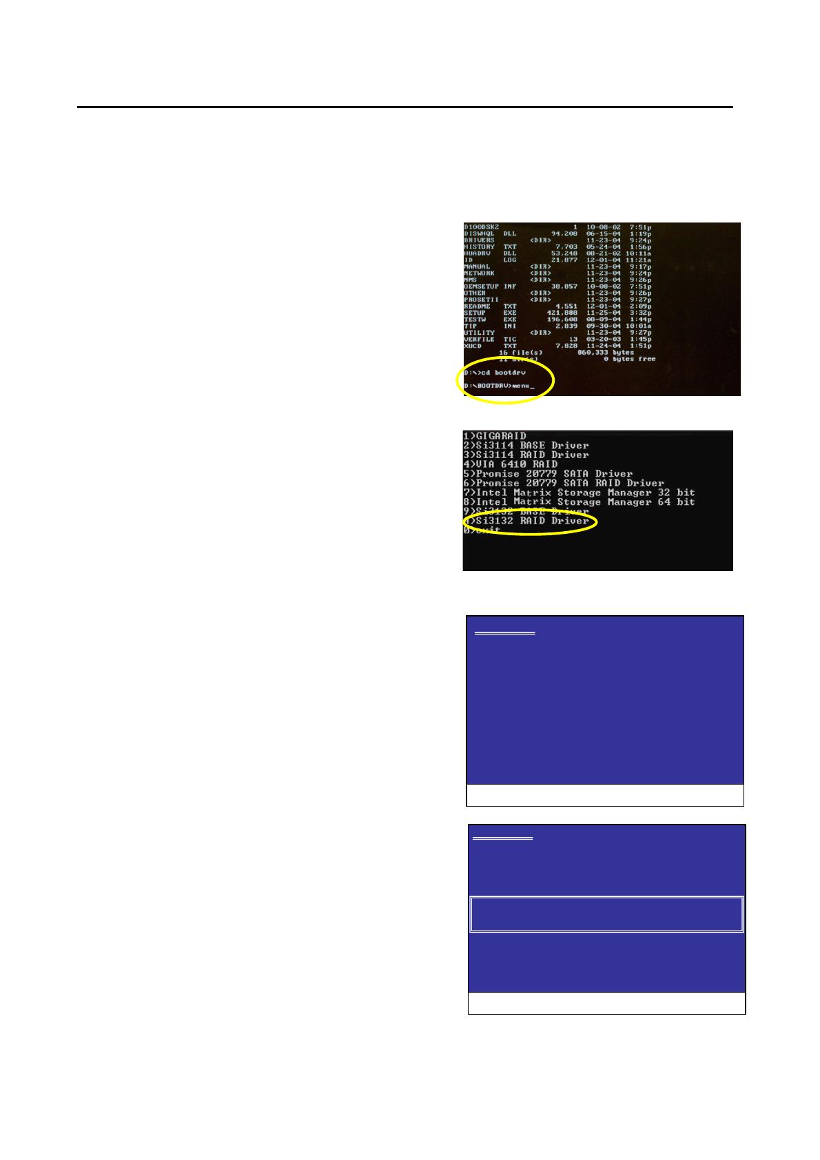
Step 1: Insert the prepared startup disk and motherboard driver CD-
ROM in your system. Boot from the startup disk. Once at the A:\>
prompt, change to the CD-ROM drive (example: D:\>). At the D:\>
prompt, type the following two commands. Press ENTER after each
command (Figure 1):
cd bootdrv
menu
Note: For users without a startup disk.
Use an alternative system and insert the GIGABYTE motherboard driver
CD-ROM. From the CD-ROM drive (example: D:) double-click the
MENU.exe file in the BootDrv folder. A command prompt window will
open similar to that in Figure 2.
Step 2: When the controller menu (Figure 2) appears, remove the
startup disk and insert the blank formatted disk. Select the Si3132
RAID
(note)
Driver by pressing the corresponding letter from the menu.
Your system will then automatically zip and transfer this driver file to the
floppy disk. Press 0 to exit when finished.
Step 3: To install an operating system, boot from the Windows
installation disk. Press F6 as soon as you see the "Press F6 if you need
to install a third party SCSI or RAID driver" message (Figure 3). In the
next screen, press S to specify additional device(s) as instructed and
supply the Serial ATA controller driver on the floppy disk.
Step 4: When a controller menu appears (Figure 4), select a controller
based on the operating system you wish to install and press ENTER.
Press ENTER again in the next screen to begin installing the driver.
When the driver installation is finished, proceed with the installation of
the Windows operating system.
Windows Setup
Press F6 if you need to install a third party SCSI or RAID driver
(Note): If you wish to set up a non-RAID configuration, please
select Si3132 BASE Driver.
Figure 1
Figure 2
Figure 3
Figure 4
Windows Setup
You have chosen to configure a SCSI Adapter for use with Windows,
using a device support disk provided by an adapter manufacturer.
Select the SCSI Adapter you want from the following list, or press ESC
to return to the previous screen.
Silicon Image SiI 3132 SATARaid Controller for Windows XP/Server 2003
Silicon Image SiI 3132 SATARaid Controller for Windows 2000
ENTER= Select F3=Exit
SATARAID5 User’s Manual
7
4 JAVA 2 Runtime Environment Installation
The Java 2 Runtime Environment is required for the SATARAID5 GUI. The Java 2 Runtime Installer and executable package
must be downloaded from the Sun Microsystems website at http://java.sun.com/j2se/downloads.html. The computer must have
an Internet connection set up before installation can proceed.
Save the installer file to a known location, such as the My Documents folder. Using Windows Explorer or by clicking on the My
Computer icon on the desktop, select the installation file and open it. The installation will begin. The installer program will
download the needed files from the Internet. (You may also install the J2RE from motherboard driver CD.
When a window appears asking for acceptance the license agreement, select I accept the terms of this license agreement and
click Next.
SATARAID5 User’s Manual
8
Choose the Typical setup type and click Next.
When the installation completes, click Finish. Restart the computer when prompted.
SATARAID5 User’s Manual
9
5 SATARAID5 GUI Installation
Insert the motherboard driver CD into the computer’s CD-ROM drive. When the autorun window appears, click the
SOFTWARE APPLICATIONS button at the left of the window. Find the Silicon Image SATA RAID Utility and install it.
Click the Next button when the Welcome window appears.
Click the Next button to install the SATARAID5 program in the default directory (recommended). An alternate directory may be
selected if desired.
After installation is done, click the Finish button to complete the installation.
SATARAID5 User’s Manual
10
6 Creating and Deleting Legacy RAID Groups with BIOS
Utility
Legacy RAID sets can be created and managed by either the BIOS utility or the SATARAID5 GUI. New RAID groups must be
created and managed by the SATARAID5 GUI. See section 8 SATARAID5 GUI Overview for information on configuring
RAID Groups using the SATARAID5 GUI.
During boot up, a screen similar to that below will appear for about 5 seconds. Press CTRL+S or the F4 key to enter the BIOS
RAID utility.
The RAID Utility menu screen will be displayed. A brief description of each section is presented on the next page.
SiI 3132 SATARaid BIOS Version 7.2.14
Copyright (C) 1997-2005 Silicon Image, Inc.
Press <Ctrl+S> or F4 to enter RAID utility
0 ST3120026AS
1 ST3120026AS
SATARAID5 User’s Manual
11
Main Menu
The Main Menu in the upper left corner is used to choose the operation to be performed. The selections are:
Create RAID Group
Delete RAID Group
Rebuild RAID 1 Set
Low Level Format
Logical Drive Info
Create RAID Group is used to create a new legacy RAID Set or for allocating legacy spare drives.
Delete RAID Group is used to delete a legacy RAID Set or to deallocate a legacy spare drive.
Rebuild RAID 1 Set is used to initiate the rebuild of a RAID 1 set after, for example, a drive in the Group has been replaced.
Low Level Format allows a single drive to have its data completely wiped out. Drives assigned to Sets or allocated as spares
cannot be low level formatted.
Logical Drive Info shows the current configuration of each RAID set, allocated spare, and unallocated physical drive attached
to the SATA host adapter.
These operations are detailed in the pages that follow.
Help Window
This window displays context-sensitive help and status messages.
Physical Drive Information
This window displays the model number and capacities of the drives physically attached to the SATA host adapter.
Logical Drive Information
This window displays all logical drives connected to the controller. The upper part lists RAID sets and CONCATENATION
drives reported to the system BIOS. The lower part lists spare drives, reserved drives, and invalid drives not reported to the
system BIOS.
Command Line
The bottom line of the display lists the currently active command keys:
Up and Down arrows select the menu item or action
ESC takes the user to the previous menu
Enter selects the highlighted choice
Ctrl-E exits the utility
Other keys may be active depending upon the currently selected action.
SATARAID5 User’s Manual
12
6.1 Creating RAID Groups
As previously discussed, the Silicon Image SATA host adapter supports RAID 0 and RAID 1 configurations. The selection of
the RAID level to be used should be based upon factors including performance, data security, and number of drives available.
It is best to carefully consider the long-term role of the system and plan the data storage strategy appropriately.
Silicon Image has made the creation of RAID sets very simple. They can be created either automatically or to allow the
greatest flexibility, manually.
1. Select “Create RAID set”
2. Choose a RAID 0 Striped or a RAID 1 Mirrored set.
3. Select Automatically or Manually configuration of the RAID Set.
SATARAID5 User’s Manual
13
4. If manual configuration is selected, the chunk size of Striped Sets can be selected. For Mirrored Sets, the Source and
Target drives can be selected.
5. If auto configuration is selected, BIOS will select RAID member drives automatically and the chunk size of Striped Sets is
set to 64KB.
6. Select RAID set size with and keys. See section 6.8 for explanation on selecting size.
7. After the RAID set size is set, the message “Are You Sure?” will display before completing the configuration. Answer “N”
to abort the creation of the new RAID set, or “Y” to proceed with the RAID set creation.
8. RAID sets can be created in both BIOS and in the SATARaid5 GUI. If you have excess capacity left on your hard drives
after creating a RAID set in the BIOS, you can later go to the SATARaid5 GUI to create additional logical drives that fully
utilize the capacity on all your hard drives
6.2 Creating Spare Drive
If there is a RAID 1, spare drive can be created. The spare drive can be allocated to the RAID 1 set in the event of a failure of
one of the drives in the RAID 1 set.
1. To create a spare drive for RAID 1 set, Select “Create RAID set”
2. Select “Spare Drive” and press Enter.
3. Select spare drive from the physical drive list and press Enter.
4. Select spare drive size with and keys. See section 6.8 for explanation on selecting size.
5. After the spare drive size is set, the message “Are You Sure?” will display before completing the configuration. Answer
“N” to abort the creation of the spare drive, or “Y” to proceed with the spare drive creation.
6.3 Creating CONCATENATION
Since BIOS no longer reports non-RAID drives to the system BIOS, if a non-RAID boot drive or data drive is desired, a
CONCATENATION can be created so BIOS will report it to the system BIOS.
1. To create a CONCATENATION, Select ”Create RAID set”
2. Select “CONCATENATION” and press Enter.
3. Select the number of CONCATENATION drive (1~2) and press Enter.
4. Select CONCATENATION drive from the physical drive list and press Enter.
SATARAID5 User’s Manual
14
After the CONCATENATION drive(s) is set, the message “Are You Sure?” will display before completing the configuration.
Answer “N” to abort the creation of the CONCATENATION, or “Y” to proceed with the CONCATENATION creation.
6.4 Deleting RAID Groups, Spare Drive, and Concatenation
1. To remove one or more RAID sets, spare drives, and concatenations, select “Delete RAID set”
2. Select the desired item to delete from the logical drive list and press Enter.
3. Press “Y” when asked, “Are You Sure?”
4. The drives will be returned to the selection of logical drives from which a new RAID set can be created.
SATARAID5 User’s Manual
15
6.5 Rebuild RAID 1 Set
This menu selection is used to initiate the copying of data from an existing drive to a replacement drive that has been installed
in a RAID 1 set after the failure of one of the members.
1. Select “Rebuild RAID 1 set”
2. Select the desired set and press Enter.
3. Press “Y” when asked, “Are You Sure?”
4. The set will be rebuilt. The status of the rebuild is displayed in the MAIN MENU window.
SATARAID5 User’s Manual
16
6.6 Low Level Formatting
The Low Level Format menu selection allows the complete erasure of data on a hard drive. This is not an action, which
typically needs to be performed as formatting the drive under Windows is usually sufficient to prepare the drive for use.
6.7 Logical Drive Information
This menu item allows the display of the assignment of physical drives within a logical set (RAID set, RAID 1 spare, or
unassigned). It is a display-only function. Use the up and down arrow keys to scroll between the drives in the Logical Drive
Properties window. Press the ESC key when done viewing logical drive information.
6.8 Reserved Drive and Setting Size for RAID Set or Spare Drive
Once a physical drive has been used to create a RAID set or spare drive by BIOS utility, BIOS saves user selected set or drive
size in the reserved area of the physical drive. There is no way to remove the reserved area information even after the user
deletes the set or drive. For this reason, after a set or drive is deleted, BIOS recognizes the physical drive as a reserved
logical drive and it will not report the drive to the system BIOS.
SATARAID5 User’s Manual
17
When user selects to create a RAID set or spare drive, he or she has to select size for the set or drive. BIOS will set a default
size for it and user can use the and keys to change the size. If the physical drive has never been used to create a set or
drive by the BIOS before, the full size of the physical drive will be set as default size. Otherwise, BIOS will set default size to
the size it saved in the reserved area of the physical drive before.
If the user wants to increase the default size, BIOS will display a warning message in the help window and for user’s response
before changing the default size.
SATARAID5 User’s Manual
18
7 Allocating Partitions in Windows
After the Raid groups have been created either using BIOS RAID utility or SATARAID5 GUI, the Raid group must have a
partition defined on it, then the Raid group must be formatted in preparation for use under Windows.
Windows XP, 2000, and Server 2003 use the Disk Management utility that is part of the Operating System. There are enough
nuances that make it important to follow the procedure specific to the Operating System.
7.1 Windows Server 2003 & XP & 2000
Before creating any partitions, RAID groups must first be created using the BIOS RAID Utility or the SATARAID5 GUI. Once
the sets have been created, allow the system to load Windows. Once Windows is running, open the Disk Management window
located at:
Control Panel> Administrative Tools> Computer Management> Storage> Disk Management
A window similar to the following should appear:
This window has three main sections:
1) System listing of all formatted and available disks/RAID Groups.
2) Report of physical connection of disks/RAID Groups.
3) Report of partition status, disk letter, and volume name.
In the physical connection window, every disk should report as:
Basic
Disk Size (the actual available disk space will be reported here)
Online
SATARAID5 User’s Manual
19
Instead of “Basic,” a disk may also report as either “Unknown” or “Dynamic.” If the disk reports as “Unknown” right-click on the
disk icon and click “Write Signature.” A window will appear with the disk in question (all “Unknown” disks may appear in this
window). Make sure the box next to each disk is checked, and then click OK. The disk should now report as “Basic.”
If a disk reports as “Dynamic,” right-click on the icon of that disk, and click on “Revert to Basic Disk...” Within seconds the disk
should report as Basic.
7.1.1 Creating the Partitions
In the Report of physical connection of disks/RAID Groups section, the order in which the drives are displayed corresponds
directly to the order the Sets appear in the BIOS. Therefore, the first Unallocated Partition represents Set 1, and so on.
1. In this example, there are two disks with unallocated partitions. Right-click on the partition of the first disk and click on
“Create Partition...”
2. The “Create Partition Wizard” should appear. The first window is an introductory window to the Wizard. Click Next.
3. The second window designates the partition type. Choose primary partition and click Next.
SATARAID5 User’s Manual
20
4. The third window designates the partition size. Since this is a Striped RAID set utilizing 2 disk drives, the size of the
partition will be approximately twice the size of the smallest single disk drive. Click Next.
5. The fourth window designates the drive letter of the partition. Change the drive letter if desired. Click Next.
  • Page 1 1
  • Page 2 2
  • Page 3 3
  • Page 4 4
  • Page 5 5
  • Page 6 6
  • Page 7 7
  • Page 8 8
  • Page 9 9
  • Page 10 10
  • Page 11 11
  • Page 12 12
  • Page 13 13
  • Page 14 14
  • Page 15 15
  • Page 16 16
  • Page 17 17
  • Page 18 18
  • Page 19 19
  • Page 20 20
  • Page 21 21
  • Page 22 22
  • Page 23 23
  • Page 24 24
  • Page 25 25
  • Page 26 26
  • Page 27 27
  • Page 28 28
  • Page 29 29
  • Page 30 30
  • Page 31 31
  • Page 32 32
  • Page 33 33
  • Page 34 34
  • Page 35 35
  • Page 36 36
  • Page 37 37
  • Page 38 38
  • Page 39 39
  • Page 40 40
  • Page 41 41
  • Page 42 42
  • Page 43 43
  • Page 44 44
  • Page 45 45
  • Page 46 46
  • Page 47 47
  • Page 48 48

Gigabyte GA-8I955X Royal User manual

Category
Peripheral controllers
Type
User manual

The Gigabyte GA-8I955X Royal motherboard boasts cutting-edge features for an exceptional computing experience. With its Intel 955X Express Chipset and support for the latest LGA775 CPUs, including Core 2 Duo and Core 2 Quad processors, this motherboard unleashes powerful performance for demanding applications and multitasking. It also features DDR2 memory technology, delivering faster data transfer speeds and enhanced system responsiveness.

Ask a question and I''ll find the answer in the document

Finding information in a document is now easier with AI