
L2 / L3 Switches
Quality of Service (QoS)
Configuration Guide
Revision 1.0

Supermicro L2/L3 Switches Configuration Guide
2
The information in this USER’S MANUAL has been carefully reviewed and is believed to be accurate. Thevendor
assumes no responsibility for any inaccuracies that may be contained in this document, makes no commitment to
update or to keep current the information in this manual, or to notify any person organization of the updates.
Please Note: For the most up-to-date version of this manual, please seeour web site at www.supermicro.com.
Super Micro Computer, Inc. (“Supermicro”) reserves the right to make changes to the product describedin this
manual at any time and without notice. This product, including software, if any, and documentation may not, in
whole or in part, be copied, photocopied, reproduced, translated or reduced to any medium or machine without
prior written consent.
IN NO EVENT WILL SUPERMICRO BE LIABLE FOR DIRECT, INDIRECT, SPECIAL, INCIDENTAL,SPECULATIVE OR
CONSEQUENTIAL DAMAGES ARISING FROM THE USE OR INABILITY TO USE THIS PRODUCT OR DOCUMENTATION,
EVEN IF ADVISED OF THE POSSIBILITY OF SUCH DAMAGES. IN PARTICULAR, SUPERMICRO SHALL NOT HAVE
LIABILITY FOR ANY HARDWARE, SOFTWARE, OR DATA STORED OR USED WITH THE PRODUCT, INCLUDING THE
COSTS OF REPAIRING, REPLACING, INTEGRATING, INSTALLING OR RECOVERING SUCH HARDWARE, SOFTWARE, OR
DATA.
Any disputes arising between manufacturer and customer shall be governed by the laws of Santa ClaraCounty in
the State of California, USA. The State of California, County of Santa Clara shall be theexclusive venue for the
resolution of any such disputes. Super Micro's total liability for all claims will notexceed the price paid for the
hardware product.
FCC Statement: This equipment has been tested and found to comply with the limits for a Class A digitaldevice
pursuant to Part 15 of the FCC Rules. These limits are designed to provide reasonable protectionagainst harmful
interference when the equipment is operated in a commercial environment. Thisequipment generates, uses, and
can radiate radio frequency energy and, if not installed and used inaccordance with the manufacturer’s instruction
manual, may cause harmful interference with radiocommunications. Operation of this equipment in a residential
area is likely to cause harmful interference, in which case you will be required to correct the interference at your
own expense.
California Best Management Practices Regulations for Perchlorate Materials: This Perchlorate warningapplies only
to products containing CR (Manganese Dioxide) Lithium coin cells. PerchlorateMaterial-special handling may apply.
See http://www.dtsc.ca.gov/hazardouswaste/perchlorate/ for furtherdetails.
Manual Revision 1.0
Release Date: October 23, 2013
Unless you request and receive written permission from Super Micro Computer, Inc., you may not copyany part of
this document.
Information in this document is subject to change without notice. Other products and companies referred to
herein are trademarks or registered trademarks of their respective companies or mark holders.
Copyright © 2013 by Super Micro Computer, Inc.
All rights reserved.
Printed in the United States of America

Supermicro L2/L3 Switches Configuration Guide
3
Contents
1 QoS Configuration Guide ...................................................................................................................... 4
1.1 QoS Overview ................................................................................................................................ 4
1.2 Policy-Based QoS ........................................................................................................................... 6
1.2.1 Classification and Marking .................................................................................................... 6
1.2.2 Policing .................................................................................................................................. 7
1.3 CoS-Based QoS .............................................................................................................................. 7
1.3.1 Egress Queuing ...................................................................................................................... 7
1.3.2 Scheduling ............................................................................................................................. 8
1.3.3 Default Priority ...................................................................................................................... 9
1.3.4 Bandwidth Management .................................................................................................... 10
1.4 Port-Based Rate Limit ................................................................................................................. 10
1.5 HOL blocking prevention ............................................................................................................. 10
1.6 QoS Configuration ....................................................................................................................... 10
1.6.1 Default Configuration .......................................................................................................... 10
1.6.2 Enabling QoS ....................................................................................................................... 11
1.6.3 Configuring Policy-Based QoS ............................................................................................. 12
1.6.4 Configuring CoS-Based QoS ................................................................................................ 19
1.6.5 Configuring Port Rate Limit ................................................................................................. 24
1.6.6 Configuring HOL Blocking Prevention ................................................................................. 25

Supermicro L2/L3 Switches Configuration Guide
4
1 QoS Configuration Guide
This document describes the system features supported in Supermicro Layer 2 / Layer 3 switches. This
document describes the system features supported in Supermicro Layer 2 / Layer 3 switch products.
This document covers the system configurations for the below listed Supermicro switch products.
The majority of this document applies to the above listed Supermicro switch products. In any particular
subsection however, the contents might vary across these product models. In those sections, the
differences are clearly identified with reference to a particular model(s). If any particular model is not
referenced, the reader can safely assume that the content is applicable to all the above listed models.
Throughout this document, the common term “switch” refers to any of the above listed
Supermicro switch models unless a particular model is noted.
1.1 QoS Overview
Typically, networks operate on a best-effort delivery basis providing all traffic equal priorityand an equal
chance of being delivered in a timely manner. However, during congestion, all traffic has anequal chance
of being dropped.The QoS featureallows one to select specific network traffic and prioritize it according
toits relative importancetoprovide preferential treatment. Implementing QoS makes network
performance morepredictable and bandwidth utilization more effective.
The QoS implementation in Supermicro switches is based on the Differentiated Services
(DiffServ)architecture. DiffServarchitecture specifies that each packetis classified upon entry into the
Top of Rack Switches
• SSE-G24-TG4
• SSE-G48-TG4
• SSE-X24S
• SSE-X3348S
• SSE-X3348T
Blade Switches
• SBM-GEM-X2C
• SBM-GEM-X2C+
• SBM-GEM-X3S+
• SBM-XEM-X10SM

Supermicro L2/L3 Switches Configuration Guide
5
network.The classification is carried in the IP packet header using six bits from the deprecated IP type of
service(ToS) field to carry the classification (class) information. Classification can also be carried in
theLayer 2 frame.
• Classification bits in Layer 2 frames:
Layer 2 frame headers contain a class of service (CoS) value as a 3-bit field in the VLAN Header. Layer 2
CoS values range from 0 for low priority to 7 for high priority.
• Classification bits in Layer 3 packets:
Layer 3 IP packets can carry either an IP precedence value or a Differentiated Services Code Point(DSCP)
value. QoS supports the use of either value because DSCP values are backward-compatiblewith IP
precedence values.IP precedence values range from 0 to 7.DSCP values range from 0 to 63.
The sameforwarding treatment is provided to packets with the same class information and different
treatment to packets withdifferent class information. The class information in the packet can be
assigned by end hosts or byother switches or routers based on a configured policy, detailed examination
of the packet, orboth.
Switches and routers use the class information to limit the amount of resourcesallocated per traffic
class. The behavior of a switch/router when handling traffic in the DiffServarchitecture is called per-hop
behavior. All devices along a network path must provide a consistent per-hop behavior in an end-to-end
QoS solution.
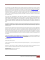
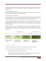
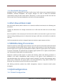
Figure QoS-1: QoS Model
The QoS Model can be divided into Ingress packet processing and Egress packet processing.
Actions at the ingress interface include classifying traffic, policing, and marking:
• Classifying distinguishes one kind of traffic from another.
• Policing determines whether a packet is in or out of profile according to the configured policer.
The policeralso limits the bandwidth consumed by a flow of traffic.
Ingress Processing
Egress Processing
Forwards or drops
data based on policy
Modifies DSCP
and/or CoS values
Egress queue
handling for data,
based on CoS
Classifies data based
on ACL
Classification Policing
Marking
Queuing and
Scheduling

Supermicro L2/L3 Switches Configuration Guide
6
• Marking allows for the differentiation of packets by designating different identifying values, e.g.
packets can be marked by setting the IP precedence bits or the IP differentiated services code
point (DSCP) in the type of service (ToS) byte.
Actions at the egress interface include queuing and scheduling:
• Queuing evaluates the CoS value and determines in which of the eight egress queues to
placethe packet.
• Scheduling services the eight egress queues based on a configured scheduling algorithm.
1.2 Policy-Based QoS
Supermicro switch features based on QoS Policies are:
• QoS Classification
• Marking
• Policing
1.2.1 Classification and Marking
Classification is the process of distinguishing one kind of traffic from another by examining the fieldsin
the packet. Supermicro switches use ACL’s to specify the fields in the frame or packet based on which
incoming IP traffic is classified.
Classification is enabled only if QoS is globally enabled on the switch. QoS isglobally disabledby default,
so no classification occurs.In Supermicro switches, classification can be configured for all interfaces of
the switch or for particular interfaces only.
After classification, the packet is sentfor policing, marking, queuing and scheduling.Marking is the
process of setting or modifying values in the classified traffic. In Supermicro switches, marking can be
configured using a policy map.
1.2.1.1 ClassMap and PolicyMap
IP standard, IP extended, and Layer 2 MAC access control lists (ACLs) can be used to define a group
ofpackets with the same characteristics (class). Only the permit action of ACL’s is permitted for use with
QoS.
The
Deny
and
Redirect
ACL actions are n
ot applicable for QoS.
Afteran ACL is associated with a class-map, it can be applied for QoS. When such a configured ACL has a
match with a permit action, further classification can be doneusing a policymap.A policy map specifies

Supermicro L2/L3 Switches Configuration Guide
7
the actions to perform for the traffic class of a class-map. Actions can include setting a specific DSCP
value or the action to take when the traffic is out of profile.
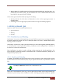
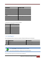
An ACL must be created for each policy and class-map,If more thanone type of traffic needs to be
classified, another ACL and class map can be created and associated. This relationship between the ACL,
class map and policy map is depicted below.
Figure QoS-2: Relationship: ACL, Policy Map & Class Map
1.2.2 Policing
Policing involves creating a policer that specifies the bandwidth limits for the traffic. Each policer
specifies the action to take for packets thatare in or out of profile. Packets that exceedthe limits are out
of profile and various actions are carried out by the marker on out of profile packets, which may
includedropping the packet or markingdown the packet with a new user-defined value.
1.3 CoS-Based QoS
Supermicro switch features based on Class of Service (CoS) are:
• Queuing
• Scheduling
• Bandwidth Management
• Default Priority
1.3.1 Egress Queuing
The CoS priority of a packet is mapped to a traffic class.Supermicro switchesprovide support to configure
the mapping of CoS priority to a traffic class.Each traffic class is mapped to eight egress queues in the
switch.
Policy Map
Class Map
ACL

Supermicro L2/L3 Switches Configuration Guide
8
The traffic class is taken from the CoS value of the ingress packet. If an ingress packet does not have a
CoS (untagged packets), the port default priority will be used.
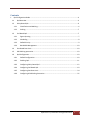
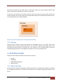
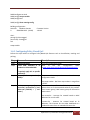
Ingress Packets CoS-to-Traffic-class mappingEgress QueueEgress Packets
Figure QoS-3: Egress Queuing
The above figure shows the egress queuing procedure. When a tagged packet with CoS value 3(packet1)
arrives in the switch, the CoS to egress queuemapping for the particular destination port is lookedup.
Based on CoS to egress queue mapping, packets with CoS value 3 are queued in Queue-3 and
transmitted. Similarly, when a tagged packet with CoS value 7(packet2) arrives in switch, the CoS to
egress queue mapping for the particular destination port is lookedup. Based on CoS to egress queue
mapping, packets with CoS value 7 are queued in Queue-7 and transmitted.
1.3.2 Scheduling
Supermicro switches support eight CoS queues for each egress port. For each of the eightqueues,
various typesof scheduling can be configured:
Strict Priority
Strict priority scheduling is based on the priority of queues. Packets in ahigh-priority queue arealways
sent first and packets in alow-priority queue are not sent until all the high-priority queuesareempty.
Round Robin(RR)
Using the round-robin (RR) scheduling algorithm, packets in queues are transmitted in a FIFO
manner,i.e. one packet after the other. All queues havethe same priority and weight in an RR
configuration.
CoS Traffic Class
0
0
1
1
2
2
3
3
4
4
5
5
6
6
7
7
0
1
2
3 Pkt1
4
5
6
7 Pkt 2
Packet 1 with CoS 3
Packet 2 with CoS 7
Packet 1 with CoS 3
Packet 2 with CoS 7

Supermicro L2/L3 Switches Configuration Guide
9
Weighted RoundRobin (WRR)
In WRR scheduling, theuser specifies a number to indicate the importance (weight) of thequeue relative
to the other CoS queues. WRR scheduling prevents low-priority queues frombeing completely neglected
during periods of high-priority traffic. The WRR scheduler sends somepackets from each queue in turn.
The number of packets it sends corresponds to the relativeimportance of the queue. By using WRR,low-
priority queues can send packets even when high-priority queues are not empty.
DeficitWRR
Bandwidth allocation can be unfair when the average packet sizes are different between the queues and
their flows. This behavior can result in service degradation for queues with smaller average packet sizes.
Deficit Weighted Round Robin (DWRR) is a modified weighted round-robin scheduling that can handle
packets of variable size.
1.3.3 Default Priority
The Class of Service (CoS) priority field is taken from the VLAN header of a received packet. If the
received packet does not have a VLAN header, the default port priority is used as the CoS value.
Supermicro switches provide an option to configure the default priority.
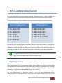
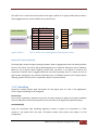
Figure QoS-4: VLAN Tag and CoS Priority
In the above figures, CoS priority is a 3-bit field in a tagged frame that indicates the frame priority level,
ranging from 0 (best effort) to 7 (highest) with 1 representing the lowest priority. These values can be
used to prioritize different classes of traffic (voice, video, data, etc.).
For IEEE 802.1Q frames with tag information, the priority value from the header frame is used. For
native frames, the default priority of the input port is used. Supermicro switches allow users to
configure the default port priority.
Each ingress port on the switch has a single receive queue buffer for incoming traffic. When an untagged
frame arrives, it is assigned the value of the port as its port default priority. Tagged frames use the
assigned CoS value when it passes through the ingress port.
CoS C
Priority F VLAN ID
I

Supermicro L2/L3 Switches Configuration Guide
10
1.3.4 Bandwidth Management
Bandwidth limiting is configured at the level of traffic classes. Traffic classes can be assigned minimum
bandwidths, maximum bandwidths, and weights. Weights are used to divide the bandwidth
proportionally among all traffic classes within a QoS policy, in such a way that a traffic class does not
receive more than its maximum bandwidth or less than its minimum bandwidth.
1.4 Port-Based Rate Limit
Rate limits define which packets conform to or exceed the defined rate based on the following two
parameters:
Average rate determines the average transmission rate. Traffic that falls under this rate will always
conform.
Burst size specifies in bits (or bytes) per burst how much traffic can be sent within a given unit of time
without causing scheduling concerns. It determines how large a traffic burst can be before it exceeds the
rate limit.
Traffic that exceeds the rate limit is dropped. Supermicro switches support output rate limits.
1.5 HOLBlocking Prevention
Supermicro switches provide eight egress queues per port. Each queue has a dynamic packet limit based
on the availability of packet buffer memory. When a switch receives packets at a fast rate destined to a
particular egress port, its egress port queuesbecome filled up. When the egress queue is full, all packets
at ingress are dropped. This phenomenon of dropping ingress packets due to egress port/CoS queue
over-subscriptionis called Head of Line (HOL) blocking.
Supermicro switches provide support to prevent HOL blocking. When HOL blocking prevention is
enabled in the switch, itdropspackets newly arriving on the ingress if they aredestined to an
oversubscribed egress port, based on the egress queue threshold. The switch stops dropping ingress
packets once it determines the egress queue is not over-subscribed by using specific counters and
thresholds. This mechanism ensures fair access to all port buffers.
HOL blocking prevention provides lossy buffer management, however it improves overall system
throughput.
1.6 QoSConfiguration
1.6.1 Default Configuration

Supermicro L2/L3 Switches Configuration Guide
11
Parameter Default Value
QoS
S
tatus
Disabled
Class
M
ap
None
Policy
M
ap
None
Default
P
riority
0
Minimum
B
andwidth
0
Maximum
B
andwidth
0
Weight
1
Scheduling
A
lgorithm
Strict
Queuing
Rate
L
imit
0
Burst
S
ize
0
HOL
Enabled
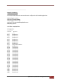
The default priority to traffic classqueue mapping:
Priority Traffic Class queue
0
0
1
1
2
2
3
3
4
4
5
5
6
6
7
7
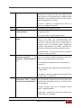
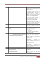
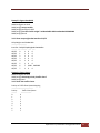
1.6.2 EnablingQoS
QoS is disabled by default in Supermicro switches. Follow the below steps to enable QoS.
Step Command Description
Step 1
configure terminal
Enters the configuration mode
Step 2
set qos enable
Enables
QoS
on all interfaces
Step 3
E
nd
Exit
s the
c
onfiguration mode
The “
set qos disable
” command disables QoS in the switch.
QoS must be enabled before configuring any of the QoS features.
The example below shows the commands used to enable QoS.

Supermicro L2/L3 Switches Configuration Guide
12
SMIS# configure terminal
SMIS(config)# set qos enable
SMIS(config)# end
SMIS(config)# show running-config
Building configuration...
Switch ID Hardware Version Firmware Version
0 SBM-GEM-X3S+ (B4-01) 1.0.14-3
vlan 1
portsgi 0/1-24 untagged
ports ex 0/1-3 untagged
exit
setqos enable
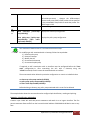
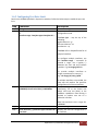
1.6.3 ConfiguringPolicy-Based QoS
Follow the steps below to configure Policy-Based QoS features such as classification, marking and
policing.
Step Command Description
Step 1
configure terminal
Enters the configuration mode
Step2
Create
MAC Extended or IP
Standard or IP Extended ACL.
If required, apply ACL to specific
Interface(s).
Refer
to the
ACL Configuration Guide
atwww.supermicro.com/products/nfo/networking.cfm.
Step 3
class
-
map <class
-
map
-
number(1
-
65535)>
Creates a class map and
enters the class
-
map
configuration mode.
class-map-number - QoS class map number in range from
1-65535.
Step 4
match access
-
group { mac
-
access-list | ip-access-list } { <acl-
index-num (1-65535) > | <acl-
name> }
This command specifies the fields in the i
ncoming
packets that are to be examined toclassify the packets.
The IP access group / MAC access group can be used as
matchcriteria.
mac-access-list - Accesses list created based on MAC
addresses for non-IP traffic
ip-access-list - Accesses list created based on IP
addresses. The IP-access list can either bedefined as a
standard IP-access list or an extended IP-access list.

Supermicro L2/L3 Switches Configuration Guide
13
acl-index-num - Specifies the ACL index range. The ACL
index range for an IP standard ACLis 1 to 1000 and 1001
to 65535for an IP extended ACL. The ACL index range for
a MAC extendedACL is 1 to 65535.
ACL-name – Specifies the configured ACL name as a
string not exceeding 32 characters
Step 5
E
xit
Exit
s the
class
map configuration mode.
Step 6
policy
-
map <policy
-
map
-
number(1-65535)>
Create
s
a policy map and enter
s
the policy
-
map
configuration mode.
policy-map-number - QoS policy map number
Step 7
class <class
-
map
-
number(1
-
65535)>
This command defines a traffic classification for the
policy to act upon. The class-map-number that
isspecified in the policy map ties the characteristics for
that class to the class map and its matchcriteria as
configured with the class-map global configuration
command. Uponexecution of theclass command, the
switch enters the policy-map class configuration mode.
class-map-number – The class map number to associate
the policy, in range of 1-65535
Step 8
set {cos<new
-
cos(0
-
7)> |
ipdscp<new-dscp(0-63)> | ip
precedence <new-precedence(0-
7)>}
(Optional)
Configure
s
the in
-
profile action by setting a
class of service (CoS), differentiatedservices code point
(DSCP), or IP-precedence value in the packet.
cos - New COS value assigned to the classified traffic, in
range of 0-7
ipdscp - New DSCP value assigned to the classified traffic,
in range of 0-63
ip precedence - New IP-precedence value assigned to the
classified traffic, in range of 0-7
Step 9
police <rate
-
Kbps(64
-
1048572)>
exceed-action {drop | policed-
dscp-transmit <new-dscp(0-63)>}
(Optional)
Configure
s
a policer for the classified traffic.
This command also specifies the action to be taken if the
specified rate is exceeded or if there is no match for the
policy configured.
rate-kbps- Average traffic rate in kilobitsper second
(Kbps), in range 64-1048572
exceed-action - Indicates the action of the switch when
the specified rate is exceeded.

Supermicro L2/L3 Switches Configuration Guide
14
drop
-
drops the packet
policed-dscp-transmit - changes the differentiated
services code point (DSCP) ofthe packet to that specified
in the policed-DSCP map and then sends the packet. The
DSCP range is 0-63.
Step
10
E
nd
Exit
s thec
onfiguration mode.
Step
11
show class
-
map [<class
-
map
-
num(1-65535)>]
show policy-map [<policy-map-
num(1-65535)> [class <class-
map-num(1-65535)>]
Display
s
the
c
lass
m
ap configuration.
Displays the policy map configuration.
ACL cannot be modified unless it is removed from
the
class
-
map.
For modifying an ACL associated with a classmap, follow the steps below:
1) Remove policy map
2) Remove classmap
3) Modify the ACL
4) Re-create the classmap
5) Re-create the policymap
If required, an ACL’s association with an interface must be configured before the “class-
map” configuration,i.e. after associating the ACL with a classmap using the
“match”command, the ACL cannot be associated with an interface.
These commands either delete the particular configuration or reset it to its default value.
no class-map <class-map-number(1-65535)>
no policy-map <policy-map-number(1-65535)>
no class <class-map-number(1-65535)>
Before deleting a classmap, any policy map associated with it must first be deleted.
The example below shows the commands used to configure QoS classification, marking and policing.
Example 1: Classification and Marking
Create a Layer 2 MAC ACL with two permit statements and attach it to an ingress interface. The first
permit statement allows traffic from the host with a MAC address of 00:30:48:14:c8:29to be sent to any
host.

Supermicro L2/L3 Switches Configuration Guide
15
SMIS# configure terminal
SMIS(config)# mac access-list extended mac1
SMIS(config-ext-macl)# permit host
00:30:48
:14:c8:29
any
SMIS(config-ext-macl)# exit
SMIS(config)# set qos enable
SMIS(config)# interface Gi 0/3
SMIS(config-if)# mac access-group mac1 in
SMIS(config-if)# exit
SMIS(config)# class-map 5
SMIS(config-cmap)# match access-group mac-access-list mac1
SMIS(config-cmap)# exit
SMIS(config)# policy-map 5
SMIS(config-pmap)# class 5
Existing Policymap configurations have been deleted. Please apply the policymap to make it active.
SMIS(config-pmap-c)# set cos 6
SMIS(config-pmap-c)# end
SMIS(config)# mac access-list extended mac2
SMIS(config-ext-macl)# permit host 00:b0:d0:86:bb:f7 any
SMIS(config-ext-macl)# exit
SMIS(config)# interface Gi 0/3
SMIS(config-if)# mac access-group mac2 in
SMIS(config-if)# exit
SMIS(config)# class-map 10
SMIS(config-cmap)# match access-group mac-access-list mac2
SMIS(config-cmap)# exit
SMIS(config)# policy-map 10
SMIS(config-pmap)# class 10
Existing policymap configurations have been deleted. Please apply the policymap to make it active.
SMIS(config-pmap-c)# set cos 7
SMIS(config-pmap-c)# end
SMIS# show policy-map
DiffServ Configurations:
------------------------
Quality of Service has been enabled

Supermicro L2/L3 Switches Configuration Guide
16
Policy Map 5 is active
Class Map: 5
-------------
In Profile Entry
----------------
In profile action : policed-cos6
Policy Map 10 is active
Class Map: 10
-------------
In Profile Entry
----------------
In profile action : policed-cos7
SMIS# show class-map
DiffServ Configurations:
------------------------
Class map 5
--------------
Filter ID : mac1
Filter Type : MAC-FILTER
DiffServ Configurations:
------------------------
Class map 10
--------------
Filter ID : mac2
Filter Type : MAC-FILTER
SMIS# show running-config
Building configuration...
Switch ID Hardware Version Firmware Version
0 SBM-GEM-X3S+ (B4-01) 1.0.14-3
vlan 1

Supermicro L2/L3 Switches Configuration Guide
17
portsgi 0/1-24 untagged
ports ex 0/1-3 untagged
exit
mac access-list extended mac1
permit host
00:30:48
:14:c8:29 any
exit
mac access-list extended mac2
permit host 00:b0:d0:86:bb:f7 any
exit
interfaceGi 0/3
mac access-group mac1 in
mac access-group mac2 in
exit
setqos enable
class-map 5
match access-group mac-access-list mac1
exit
class-map 10
match access-group mac-access-list mac2
exit
policy-map 5
class 5
setcos 6
exit
exit
policy-map 10
class 10
setcos 7
exit
exit
Example 2: Policing
Create a policy map for the switch without attaching it to an ingress interface. In the configuration, the
IP standard ACL permits traffic from network 20.1.0.0. For traffic matching this classification, the DSCP
value in the incoming packet is trusted. If the matched traffic exceeds an average traffic rate of 4800
bps, its DSCP is marked down to a value of 10 and transmitted.
SMIS# configure terminal
SMIS(config)# ip access-list standard 1
SMIS(config-std-nacl)# permit 20.1.0.0 255.255.0.0 any
SMIS(config-std-nacl)# exit

Supermicro L2/L3 Switches Configuration Guide
18
SMIS(config)# set qos enable
SMIS(config)# class-map 1
SMIS(config-cmap)# match access-group ip-access-list 1
SMIS(config-cmap)# exit
SMIS(config)# policy-map 1
SMIS(config-pmap)# class 1
Existing policymap configurations have been deleted. Please apply the policymap to make it active.
SMIS(config-pmap-c)# police 500000 exceed-action policed-dscp-transmit 10
SMIS(config-pmap-c)# end
SMIS# show policy-map
DiffServ Configurations:
------------------------
Quality of Service has been enabled
Policy Map 1 is active
Class Map: 1
-------------
Out Profile Entry
-----------------
Metering on
burst bytes/token size : 6
Refresh count : 500000
Out profile action : policed-dscp 10
SMIS# show class-map
DiffServ Configurations:
------------------------
Class map 1
--------------
Filter ID : 1
Filter Type : IP-FILTER
SMIS# show running-config
Building configuration...
Switch ID Hardware Version Firmware Version

Supermicro L2/L3 Switches Configuration Guide
19
0 SBM-GEM-X3S+ (B4-01) 1.0.14-3
vlan 1
portsgi 0/1-24 untagged
ports ex 0/1-3 untagged
exit
ip access-list standard 1
permit 20.1.0.0 255.255.0.0 any
exit
setqos enable
class-map 1
match access-group ip-access-list 1
exit
policy-map 1
class 1
police 500000 exceed-action policed-dscp-transmit 10
exit
exit
1.6.4 Configuring CoS-Based QoS
Follow the steps below to configure CoS-Based features such as default priority, scheduling and
bandwidth.
Step Command Description
Step 1
configure terminal
Enters the configuration mode
Step 2
vlan map
-
priority <priority value(0
-
7)> traffic
-
class <Traffic class value(0-7)>
Map
s
a priority to a traffic class in the
switch. The frame received with the
configured priority will be processed in
the configured traffic class.
Priority- Priority of the packet, in range
of 0-7.
Class –Traffic class in range of 0-7.
Step
3
interface <interface-type><interface-id>
or
interface range <interface-type><interface-id> ….
(Optional) Enters the interface
configuration mode.
interface-type – may be any of the
following:
gigabit-ethernet – gi
extreme-ethernet – ex
qx-ethernet – qx

Supermicro L2/L3 Switches Configuration Guide
20
interface-id is in slot/port format for all
physical interfaces.
To configure multiple interfaces, use
the “interface range …” command. To
provide a range use a hyphen (-)
between the start and end interface
numbers. E.g.: int range gi 0/1-10
To provide multiple interfaces or
ranges, separate with a comma (,).
E.g.: int range gi 0/1-10, gi 0/20
If multiple interfaces are provided, the
next step will perform the particular
configuration on all these interfaces.
Step
4
switchport priority default <priority
value(0
-
7)>
(Optional)
Configure
s the
default
priority for the interface in range of 0-
7.
Step
5
cosq scheduling algorithm { strict | rr | wrr |
deficit }
(Optional) Configures the QoS Egress
queue scheduling algorithm.
strict - strict
rr - round robin
wrr - weighted round robin (WRR)
deficit – deficit WRR
Step
6
traffic
-
class <integer(0
-
7)> weight <integer(0
-
15)>
[ minbandwidth<integer(64-16777152)>]
[maxbandwidth<integer(64-16777152)>]
(Optional)
Configures the
e
gress
q
ueue
minimum and maximum bandwidth.
weight - Configures the queue weights
in range of 0-15
minbandwidth - Configures the
minimum bandwidth for the queue in
range of 64-16777152
maxbandwidth - Configures the
maximum bandwidth for the queue in
range of 64-16777152
Step
7
End
Exit
s the c
onfiguration mode.
Step
8
show vlan port config port [
<
interface
-
type><interface-id>]
show vlan traffic-classes
Display
s
the
p
ort
d
efault
p
riority
configuration.
Display the traffic class and egress
queue mapping.
Page is loading ...
Page is loading ...
Page is loading ...
Page is loading ...
Page is loading ...
Page is loading ...
-
 1
1
-
 2
2
-
 3
3
-
 4
4
-
 5
5
-
 6
6
-
 7
7
-
 8
8
-
 9
9
-
 10
10
-
 11
11
-
 12
12
-
 13
13
-
 14
14
-
 15
15
-
 16
16
-
 17
17
-
 18
18
-
 19
19
-
 20
20
-
 21
21
-
 22
22
-
 23
23
-
 24
24
-
 25
25
-
 26
26


Ask a question and I''ll find the answer in the document
Finding information in a document is now easier with AI
Related papers
-
Supermicro L3 Configuration manual
-
-
Supermicro SSE-G48-TG4 Configuration manual
-
-
-
-
-
Supermicro SSE-G48-TG4 User manual
-
-
Other documents
-
AOpen AX3S-1394 Owner's manual
-
SUPER MICRO Computer SSE-G48-TG4 User manual
-
Dell PowerSwitch S5048F-ON Administrator Guide
-
-
-
Dell PowerSwitch Z9100-ON Owner's manual
-
Dell PowerSwitch S6100-ON Owner's manual
-
-
-