Page is loading ...

Introduction
The Model H7657 Miter Saw Work Stand (Figure
1) features a universal, adjustable T-track mount-
ing system for securing miter saws without modi
-
fication. Laterally and vertically adjustable ball
bearing rollers on each end of the stand support
long workpieces. Roller mounts rotate incremen
-
tally for fine height adjustment. Folding legs and
rubber wheels make this work stand portable.
MITER SAW
WORK STAND
MODEL H7657
INSTRUCTION SHEET
COPYRIGHT © JUNE, 2005 BY GRIZZLY INDUSTRIAL, INC.
WARNING: NO PORTION OF THIS MANUAL MAY BE REPRODUCED IN ANY SHAPE
OR FORM WITHOUT THE WRITTEN APPROVAL OF GRIZZLY INDUSTRIAL, INC.
#EW7281 PRINTED IN CHINA
Safety
1. MITER SAW SAFETY. Follow all safety
instructions in the miter saw manual.
2. MITER SAW WORK STAND SET UP. Make
sure the leg locking pins are fully snapped
into place before mounting the miter saw.
3. MITER SAW WORK STAND PLACEMENT.
Only operate the miter saw work stand on a
hard, flat, and level surface. DO NOT set up
the miter saw work stand on a soft surface,
such as sand or mud.
4. MITER SAW WORK STAND USAGE. Only
use the miter saw work stand to support a
miter saw. This stand is NOT intended for use
as a ladder or scaffolding.
5. WORKPIECE BALANCE. Use extra support
tables, or get assistance, when working with
large workpieces to prevent the stand from
tipping over.
6. ATTACH MITER SAW SECURELY. DO NOT
operate the miter saw unless it is securely
attached to the miter saw work stand.
7. LOCK WORK SUPPORTS. Tighten lock
knobs to secure the work supports before
using the miter saw work stand.
8. EXPERIENCING DIFFICULTIES.
If at any
time you are experiencing difficulties per
-
forming the intended operation, stop using
this stand! Contact Tech Support at (570)
546-9663 for help.
Figure 1. Model H7657.
Unpacking
The Model H7657 was carefully packed when
it left our warehouse. If you discover this stand
is damaged after you have signed for delivery,
please immediately call Customer Service at (570)
546-9663
for advice. Save the containers and all
packing materials for possible inspection by the
carrier or its agent. Otherwise, filing a freight claim
can be difficult. When you are completely satisfied
with the condition of your shipment, you should
inventory the contents.

Inventory
Box Contents: (Figure 2) Qty
A. Stand (not shown
) ...................................... 1
B.
Wheels ....................................................... 2
C. Wheel Brackets .......................................... 4
D. Roller Assembly ......................................... 2
E. Crossbar ..................................................... 2
Hardware: Qty
—Support Braces .......................................
2
—Hex Bolts M8-1.25 x 45 ..........................
2
—Hex Bolts M6-1 x 45 ............................. 12
—Flat Washers 6mm ............................... 12
—Hex Nuts M6-1 ...................................... 12
—Lock Nuts M8-1.25 ..................................
2
—Knobs M8-1.25 x 50 ...............................
4
—Knobs M8-1.25 x 20 ................................
2
—Hex Bolts M8-1.25 x 50 ..........................
4
—Hex Nuts M8-1.25 ...................................
8
—Flat Washers 8mm .................................
4
In the event that any nonproprietary parts are
missing (e.g. a nut or a washer), we would be
glad to replace them, or for the sake of expedi
-
ency, replacements can be obtained at your local
hardware store.
Assembly
This work stand comes partially assembled. You
will need to install the wheels, the support rollers,
and your miter saw.
To assemble the miter saw work stand:
1. Lay the work stand upside down and unfold
the top set of legs (inset in
Figure 3). Make
sure the locking pins snap into place.
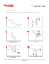
2. Place a wheel bracket on either side of the
wheel and thread an M8-1.25 x 45 hex bolt
through the assembly (
Figure 3), then secure
it with a flat washer and a lock nut.
Figure 2. Model H7657 inventory.
Figure 3. Wheel assembly.
3. Place the wheel brackets on either side of
the stand leg and thread M6-1 x 45 hex bolts
through the wheel brackets (
Figure 3) and
loosely secure them with flat washers and
hex bolts
.
4. Unfold the remaining legs and install the sup-
port braces between the legs with M6-1 x 45
hex bolts, flat washers, and hex nuts.
Note: This step is optional. Installing the sup-
port braces adds stability, but makes folding
the work stand more difficult.
B
C
D
E

Adjustment
To adjust the work stand:
1. Slide the extension arms out to their maxi-
mum reach and place a straight 2x4 across
the miter saw table and rollers.
2. Loosen the crossbar knobs and rotate the
roller assemblies until the rollers almost
touch the
2x4 as shown in Figure 6. Then
loosen the roller assembly lock knobs and
slide the rollers up to touch the
2x4.
5. Place the work stand upright, move the bot-
tom of the wheels approximately an
1
⁄8" above
the floor and tighten the hex nuts.
6. Place the roller crossbar between the exten-
sion arms and thread in the M8-1.25 x 50
knobs as shown in
Figure 4.
Figure 4. Support roller assembly.
7. Slide the roller assembly into the crossbar
and secure it with an M8-1.25 x 20 knob
(Figure 4).
8. Loosen the T-track lock knobs and adjust the
T-tracks to the width of your miter saw, then
slide the heads of two M8-1.25 x 50 hex bolts
into each T-track.
9. Place the miter saw over the bolts and secure
it with washers
and hex nuts (see Figure 5).
Figure 5. Mounting the miter saw.
Figure 6. Adjusting the support rollers.
Storage
To fold up the work stand:
1. Remove the support braces, retract the exten-
sion arms and rotate the support rollers flat.
2. Push in the locking pins shown in Figure 7
and fold the legs up into the stand.
Figure 7. Folding the miter saw work stand.
Locking Pin
Roller
Crossbar
Roller
Assembly
T-Track
T-Track
Lock Knob

H7657 Parts Breakdown and List
REF PART # DESCRIPTION REF PART # DESCRIPTION
1 PH7657001 ROLLER 18 PH7657018 SMALL AXLE
2 PH7657002 SUPPORT 19 PH7657019 RIGHT LEG
3 PH7657003 END PLUG 20 PH7657020 FOOT
4 PH7657004 BUSHING 21 PH7657021 T-TRACK LOCKING PLATE
5 PH7657005 OUTSIDE GEAR 22 PH7657022 BIG AXLE
6 PH7657006 INSIDE GEAR 23 PH7657023 LEFT LEG
7 PH7657007 LOCK KNOB M8-1.25 X 20 24 PB71M HEX BOLT M6-1 X 45
8 PH7657008 ROLLER CROSSBAR 25 PH7657025 WHEEL BRACKET
9 PH7657009 EXTENSION ARMS 26 PW03M FLAT WASHER 6MM
10 PB06M HEX BOLT M8-1.25 X 12 27 PN01M HEX NUT M6-1
11 PH7657011 STAND 28 PH7657028 WHEEL
12 PN03M HEX NUT M8-1.25 29 PB118M HEX BOLT M8-1.25 X 45
13 PH7657013 FENDER WASHER 8MM 30 PLN04M LOCK NUT M8-1.25
14 PB22M HEX BOLT M8-1.25 X 50 31 PW01M FLAT WASHER 8MM
15 PH7657015 T-TRACK 32 PH7657032 LOCK KNOB M8-1.25 X 50
16 PH7657016 COMPRESSION SPRING 33 PB03M HEX BOLT M8-1.25 X 16
17 PH7657017 PIN 34 PH7657034 SUPPORT BRACE
/