Page is loading ...

INSTALLATION MANUAL
AIR CONDITIONER
P/NO.:MFL68047202
www.lg.com
TYPE :Ceiling Concealed Duct
Please read this installation manual completely before installing the
product.
Installation work must be performed in accordance with the national wiring
standards by authorized personnel only.
Please retain this installation manual for future reference after reading it
thoroughly.
ENGLISH
MFL68047202

Introduction
Installation of Indoor,
Outdoor Unit
Connecting Pipes to the
Indoor Unit
Connecting Cables
between Indoor Unit and
Outdoor Unit
Air Purging and
Evacuation
External Static Pressure &
air Flow
Installation Guide at the
Seaside
3 Safety Precautions
4
6
7
19
Connecting Pipes to the
Outdoor Unit
21
21
Checking the Drainage
22
25
Group Control
27
38
39
TABLE OF CONTENTS
2
Important Safety Instruction
Ceiling Concealed Duct Type Air Conditioner

TIPS FOR SAVING ENERGY
Here are some tips that will help you minimize the power consumption when you use the air
conditioner. You can use your air conditioner more efficiently by referring to the instructions
below:
• Do not cool excessively indoors. This may be harmful for your health and may consume
more electricity.
• Block sunlight with blinds or curtains while you are operating the air conditioner.
• Keep doors or windows closed tightly while you are operating the air conditioner.
• Adjust the direction of the air flow vertically or horizontally to circulate indoor air.
• Speed up the fan to cool or warm indoor air quickly, in a short period of time.
• Open windows regularly for ventilation as the indoor air quality may deteriorate if the air con-
ditioner is used for many hours.
• Clean the air filter once every 2 weeks. Dust and impurities collected in the air filter may
block the air flow or weaken the cooling / dehumidifying functions.
For your records
Staple your receipt to this page in case you need it to prove the date of purchase or for warranty
purposes. Write the model number and the serial number here:
Model number :
Serial number :
You can find them on a label on the side of each unit.
Dealer’s name :
Date of purchase :
Safety Precautions

ENGLISH
IMPORTANT SAFETY INSTRUCTIONS
READ ALL INSTRUCTIONS BEFORE USING THE APPLIANCE.
Always comply with the following precautions to avoid dangerous situations and ensure peak
performance of your product
WARNING
It can result in serious injury or death when the directions are ignored
CAUTION
It can result in minor injury or product damage when the directions are ignored
WARNING
• Installation or repairs made by unqualified persons can result in hazards to you and others.
•
The product shall be installed according to the wiring regulations of the corresponding country.
• The information contained in the manual is intended for use by a qualified service technician
familiar with safety procedures and equipped with the proper tools and test instruments.
• Failure to carefully read and follow all instructions in this manual can result in equipment mal-
function, property damage, personal injury and/or death.
Installation
• Do not turn on the breaker or power under condition that front panel, cabinet, top cover, control box
cover are removed or opened.
- it may cause fire, electric shock, explosion or death.
• Do not use a defective or underrated circuit breaker. Use this appliance on a dedicated circuit.
- There is risk of fire or electric shock.
• For electrical work, contact the dealer, seller, a qualified electrician, or an Authorized Service Center.
- Do not disassemble or repair the product. There is risk of fire or electric shock.
• Always ground the product.
- There is risk of fire or electric shock.
• Install the panel and the cover of control box securely.
- There is risk of fire or electric shock.
• Always install a dedicated circuit and breaker.
- Improper wiring or installation may cause fire or electric shock
• Use the correctly rated breaker or fuse.
- There is risk of fire or electric shock.
• Do not modify or extend the power cable.
- There is risk of fire or electric shock.
• Be cautious when unpacking and installing the product.
- Sharp edges could cause injury. Be especially careful of the case edges and the fins on the con-
denser and evaporator.
• For installation, always contact the dealer or an Authorized Service Center.
- There is risk of fire, electric shock, explosion, or injury.
• Do not install the product on a defective installation stand.
- It may cause injury, accident, or damage to the product.
• Be sure the installation area does not deteriorate with age.
- If the base collapses, the air conditioner could fall with it, causing property damage, product failure,
and personal injury.
!
!
!
4
Ceiling Concealed Duct Type Air Conditioner

• Do not let the air conditioner run for a long time when the humidity is very high and a door or a win-
dow is left open.
- Moisture may condense and wet or damage furniture.
• Use a vacuum pump or Inert (nitrogen) gas when doing leakage test or air purge. Do not compress
air or Oxygen and Do not use Flammable gases. Otherwise, it may cause fire or explosion.
- There is the risk of death, injury, fire or explosion.
Operation
• Do not store or use flammable gas or combustibles near the product.
- There is risk of fire or failure of product.
CAUTION
Installation
• Always check for gas (refrigerant) leakage after installation or repair of product.
- Low refrigerant levels may cause failure of product.
• Install the drain hose to ensure that water is drained away properly.
- A bad connection may cause water leakage.
• Keep level even when installing the product.
- To avoid vibration or water leakage.
• Do not install the product where the noise or hot air from the outdoor unit could damage the neighborhoods.
- It may cause a problem for your neighbors.
• Use two or more people to lift and transport the product.
- Avoid personal injury.
• Do not install the product where it will be exposed to sea wind (salt spray) directly.
- It may cause corrosion on the product. Corrosion, particularly on the condenser and evaporator fins, could
cause product malfunction or inefficient operation.
!
Installation Manual 5

This symbol alerts you to the risk of electric shock.
This symbol alerts you to hazards that could cause harm to the
air conditioner.
This symbol indicates special notes.
NOTICE
Introduction
Symbols Used in this Manual
Features
(Side)
(Rear)
Air outlet
vents
Air intake
vents
Connecting Wire
Drain Hose
Connection Pipe
Control Cover
Air filters
Air intake vents
Remote Controller
Air outlet vents
TEMP
FAN
SPEED
OPER
MODE
6
Introduction
Ceiling Concealed Duct Type Air Conditioner

Installation of Indoor, Outdoor Unit
Installation of Indoor, Outdoor Unit
Indoor unit
Install the air conditioner in the location that
satisfies the following conditions.
The place shall easily bear a load exceeding
four times the indoor unit’s weight.
The place shall be able to inspect the unit as
the figure.
The place where the unit shall be leveled.
The place shall allow easy water
drainage.(Suitable dimension “H” is necessary
to get a slope to drain as figure.)
The place shall easily connect with the
outdoor unit.
The place where the unit is not affected by an
electrical noise.
The place where air circulation in the room will
be good .
There should not be any heat source or steam
near the unit
Outdoor unit
If an awning is built over the unit to prevent
direct sunlight or rain exposure, be careful that
heat radiation from the condenser is not
restricted.
There should not be any animals or plants
which could be affected by hot air discharged.
Ensure the spaces indicated by arrows from
the wall, ceiling,
fence or other obstacles.
Take the weight of the air conditioner into
account and select a place where noise and
vibration are minimum.
Select a place where the warm air and noise
from the air conditioner do not disturb
neighbors.
H
600600
Top view
(unit: mm)
Front view
Front
Inspection hole
(600X600)
Control box
1000
More than
30cm
More than
30cm
More than
70cm
foornuS
roecneF
selcatsbo
Selection of the best location
Installation Manual 7

Piping length and the elevation
CAUTION:
If Model is installed at a distance of 15 m, 150 g of refrigerant
should be added (15 m - 7.5 m) x 20 g/m = 150 g
is on the basis of reliability.
Outdoor unit
Indoor unit
A
B
Outdoor unit
Indoor unit
A
B
A
Oil trap
Outdoor unit
Indoor unit
B
If piping length is more than 5m
Gas
Liquid
Standard
Max.
Max
.
Pipe Size
Length A(m)
Elevation B(m)
*Additional
(Diameter:Ø)
refrigerant(g/m)
0
2
12.7
6.35
7.5 15
7
Installation of Indoor, Outdoor Unit
8
Ceiling Concealed Duct Type Air Conditioner

Installation of Unit
Install the unit above the ceiling correctly.
to absorb unnecessary vibration.
CASE 1
POSITION OF SUSPENSION BOLT
(Unit:mm)
Indoor unit
installation
ENGLISH
(Unit:mm)
708 434 51 537 230
A B C D E F G
678 525
Installation of Indoor, Outdoor Unit
ENGLISH
(Unit:mm)
as a figure for easy water drainage.
can support the weight of the unit.
vibration.
performed.
CASE 2
POSITION OF CONSOLE BOLT
Drainage hole
A
B
C D
F
G
E
M10 Nut ×4
M10 SP.Washer ×4
M10 Washer ×4
M10 Nut ×4
M10 SP.Washer ×4
M10 Washer ×4
Local
Supply
Local
Supply
Installation Manual 9

Installation of Indoor, Outdoor Unit
• Select and mark the position for fixing bolts.
• Drill the hole for set anchor on the face of
ceiling.
• Insert the set anchor and washer onto the
suspension bolts for locking the suspension
bolts on the ceiling.
• Mount the suspension bolts to the set anchor
firmly.
• Secure the installation plates onto the
suspension bolts (adjust level roughly) using
nuts, washers and spring washers.
CAUTION:
Tighten the nut and bolt to
prevent unit falling.
1 Set anchor
Old building New building
2 Plate washer
3 Spring washer
4 Nut
5 Suspension
bolts
10
Ceiling Concealed Duct Type Air Conditioner

Installation Manual 11
Installation of Indoor, Outdoor Unit
CAUTION
Drainage hole
U-Trap
B
C
A
70mm
B
2C
C
2 x SP
SP = External Pressure
(mmAq)
Ex) External Pressure
= 10mmAq
A
70mm
B
40mm
C
20mm
A
Make sure to be closed.
Unit
Drainage pipe
(Local supply)
Thermal insulator
Metal clamp
(Local supply)
(Local supply)
CAUTION FOR GRADIENT OF
UNIT AND DRAIN PIPING
Lay the drain hose with a downward
inclination so water will drain out.
Front of view
Always lay the drain with downward
inclination (1/50 to 1/100).
Prevent any upward flow or reverse flow in
any part.
5mm or thicker formed thermal insulator
Tighten the drain hose and pipe with
metal clamp
shall always be provided for the drain pipe.
Install the P-Trap (or U-Trap) to prevent
a water leakage caused by the blocking
of intake air filter.
Applied U-Trap Dimension
1. Install declination of the indoor unit is very important for the drain of the duct type air
conditioner.
2. Minimum thickness of the insulation for the connecting pipe shall be 7mm.
The unit must be horizontal or declined to the drain hose connected when finished
installation.
INCORRECT
Upward routing not
allowed
Ceiling
Drainage hole
INCORRECT CORRECT
1~3mm
Drainage hole
CORRECT

Installation of Indoor, Outdoor Unit
t Drill the piping hole with 70mm dia, hole core
drill.
t Piping hole should be slightly slant to the
outdoor side.
5~7mm
Indoor Outdoor
WALL
INSULATION, OTHERS
Insulate the joint and tubes completely.
All thermal insulation must comply with local requirement.
INDOOR UNIT
After all workings are nished, check the working and operation.
t Air distribution Is the air circulation good?
t Drain Is the drainage smoothly and no sweating?
t Gas leakage Is the piping connection correctly?
t Wiring Is the wiring connection correctly?
t Lock-bolt Is the lock-bolt of compressor loosened?
THERMAL INSULATION
TEST AND CHECK
Make sure that there is no clearance here.
Overlap with thermal
insulator for piping.
Thermal insulator for refrigerant pipe
(Local supply)
Thermal insulator for
piping(Local supply)
Hose clip for thermal insulator(Local supply)
Union for liquid pipe
Refrigerant pipe and thermal
insulator(Local supply)
Union for gas pipe
Thermal insulator for refrigerant pipe
(Local supply)
Hose clip for thermal insulator
(Local supply)
REFRIGERANT PIPE
Insulate and tape the gas piping.
CAUTION: Cutting line of
insulation must look upper
direction. Thickness of
insulation is 7mm or over.
Recommended Insulation
material
Meterial: FOAM PE
Thickness : 10mm
Density : less than 0.032±0.005(g/cm
2
)
Thermal conductivity : less than
0.03(kcal/m.hr. °C)
NOTICE
Make sure insulate and tape gas and liquid side piping entirely.
Power cable
Thermal insulator
Gas pipe
Liquid pipe
Tape
Filter Drier installation on the connecting pipe is not recommended.It can lead to capacity decreasing.
FILTER DRIER
12
Ceiling Concealed Duct Type Air Conditioner

1. Please fix tightly using provided screw after placing remote controller setup board
on the place where you like to setup.
- Please set it up not to bend because poor setup could take place if setup board bends.
Please set up remote controller board fit to the reclamation box if there is a reclamation box.
2. Can set up Wired remote controller cable into three directions.
- Setup direction: the surface of wall reclamation, upper, right
- If setting up remote controller cable into upper and right side, please set up after removing remote controller
cable guide groove.
❈
Remove guide groove with long nose.
Reclamation to the surface of the wall
Upper part guide groove
Right part guide groove
Installation instruction
<Wire guide grooves>
Installation Manual 13

Wall
Side
Wall
Side
Wall
Side
Wall
Side
<Connecting order>
<Separating order>
3. Please fix remote controller upper part into the
backplate attached to the surface of the wall, as
the picture below, and then, connect with
backplate by pressing lower part.
- Please make sure to leave no gaps on the top, bottom, left or right
sides between the remote controller and backplate.
- Before assembly with the backplate, arrange the Cable not to
interfere with circuit parts.
Remove remote controller by inserting a
screwdriver into the lower separating holes and
twisting to release the controller from backplate.
- There are two separating holes. Please individually separate one
at a time.
- Please be careful not to damage the inside
components when separating.
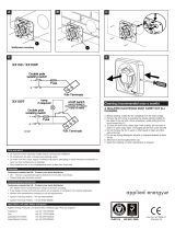
4. Please refer to the following directions when connecting the indoor unit and the
wired remote controller together.
1) Please connect the cables as shown in the figure below when connecting the plug type cable from the
indoor unit’s C/BOX and the housing type of the extension cable.
2) When connecting Terminal Blocks of the indoor C/BOX and the wired remote controller with the extension
cable, refer to the steps below.
Remove the screw on the cable which is fastened to the wired remote controller’s Terminal Block by
loosening with a screw driver.
Remove the housing of the provided 32ft extension cable with a cutting nipper and peel it as shown in the
figure below. (when purchasing the extension cable at the site directly, please peel it as shown in the figure
below.)
Please check if the connectors are connected properly.
C/BOX Cable (Plug type)
Extension cable(housing type)
Indoor
Unit side
TEMP
FAN
SPEED
OPER
MODE
• Specification of LG supplied extension cable: AWG#22, 3 core shielded. (Model : PZCWRC1)
❈ Apply enclosed noncombustible conduit(metal raceway) totally or use FT-6 rated cable or above level in
case of local electric & building code that requires plenum (CMP) cable usage.
CAUTION
Signal Yellow
12V Red
GND Black
1.378 inch(35mm)
±0.197 inch(5mm)
0.394 inch(10mm) ± 0.118 inch(3mm)
14
Ceiling Concealed Duct Type Air Conditioner

ENGLISH
5. Please use an extension cable if the distance between the wired remote controller
and the indoor unit is longer than 32ft(10m).
Ĺ
Make sure each wire is securely fastened under each screw terminal and the wires are not in contact with
each other.
ĺ
Please connect the Terminal blocks of indoor unit’s C/BOX and wired remote controller by referring to the
images and contents shown below.
Connect the yellow(signal) part of the wired remote controller’s terminal block and the ‘YL’ part of the indoor
unit’s terminal block.
Connect the red(12V) part of the wired remote controller’s terminal block and the ‘RD’ part of the indoor
unit’s terminal block.
Connect the black(GND) part of the wired remote controller’s terminal block and the ‘BK’ part of the indoor
unit’s terminal block.
In case of loosened screws or insufficient contact between the terminal and the wire, remote controller
may not function properly.
When the power is off on the remote controller, check the connection between the remote controller and
Terminal Block.
Use an appropriate screwdriver for tightening the terminal screws. A screwdriver with a small head will
strip the head and make proper tightening impossible.
Over-tightening the terminal screws may break wires and terminal block structure.
<Remote controller> <Indoor Terminal Block>
• Installation work must be performed in accordance with the national wiring standards and local by
authorized personnel only.
• Installations must comply with the applicable local/national or international standards.
• AWG#22, 3 core shielded is recommended when using the large hole in the center of the back plate.
• AWG#24, 3 core shielded is recommended when using the side or top knock-out of the back plate.
CAUTION
When installing the wired remote controller, do not bury it in the wall.
(It can cause damage in the temperature sensor.)
Do not install the cable to be 164ft(50m) or longer. (It can cause communication error.)
CAUTION
Remote controller
PCB Terminal
block Remark
Indoor
Terminal
block
Function
YELLOW YL Signal
RED RD 12V
BLACK BK GND
YELLOW RED BLACK
Signal 12V GND
Remote
controller PCB
Indoor unit
side
Installation Manual 15
Installation of Indoor, Outdoor Unit

Remote controller installation
Since the room temperature sensor is in the remote controller, the remote controller box
should be installed in a place away from direct sunlight, high humidity and direct supply of
cold air to maintain proper space temperature. Install the remote controller about 5ft(1.5m)
above the floor in an area with good air circulation at an average temperature.
Do not install the remote controller where it can be affected by:
- Drafts, or dead spots behind doors and in corners.
- Hot or cold air from ducts.
- Radiant heat from sun or appliances.
- Concealed pipes and chimneys.
- Uncontrolled areas such as an outside wall behind the remote controller.
- This remote controller is equipped with LCD display.
For proper display of the remote
controller LCD's, the remote controller should be installed properly as shown in Fig.1.
(The standard height is 4~5 ft (1.2~1.5 m) from floor level.)
TEMP
FAN
SPEED
OPER
MODE
TEMP
FAN
SPEED
OPER
MODE
TEMP
FAN
SPEED
OPER
MODE
TEMP
FAN
SPEED
OPER
MODE
5feet
(1.5meters)
(Fig. 1)
Direct
Sun ray contact area
no
no
no
yes
Installation of Indoor, Outdoor Unit
16
Ceiling Concealed Duct Type Air Conditioner


Installation of Indoor, Outdoor Unit
ELECTRICAL WIRING
Indoor unit
Remove the control box cover for
electrical connection between the
indoor and outdoor unit.
(Remove crews
.)
Use the cord clamper to fix the cord.
Perform the electrical wiring work according to the
electrical wiring connection.
All wiring must comply with local
requirements.
Select a power source that is capable of
supplying the current required by the air
conditioner.
Use a recognized circuit breaker between
the power source and the unit. A
disconnection device to adequately
disconnect all supply lines must be fitted.
Capacity of circuit breaker
WIRING CONNECTION
Outdoor unit
Remove the control cover for wiring
connection.
Use the cord clamper to fix the cord.
Earthing work
Connect the cable of diameter 1,6mm
or more to the earthing terminal
provided in the control box and do
earthing.
Please check !!
Outdoor
Indoor
Main
power source
Switch box
Circuit Breaker
Control terminal board
Cord
clamper
Cover control
Main terminal board
2
Model 1
Phase
20 A
AB-C096TLA0
AB-C126TLA0
Remote
control cord
Connection cord between
the indoor unit and the outdoor unit
A
view
A
18
Ceiling Concealed Duct Type Air Conditioner

Installation Manual 19
Connecting Pipes to the Indoor Unit
Connecting Pipes to the Indoor Unit
Main cause of gas leakage is defect in flaring
work. Carry out correct flaring work in the
following procedure.
Cut the pipes and the cable.
Use the accessory piping kit or the pipes
purchased locally.
Measure the distance between the indoor and
the outdoor unit.
Cut the pipes a little longer than measured
distance.
Cut the cable 1,5m longer than the pipe
length.
Burrs removal
Completely remove all burrs from the cut cross
section of pipe/tube.
Put the end of the copper tube/pipe to
downward direction as you remove burrs in
order to avoid to let burrs drop in the tubing.
Putting nut on
Remove flare nuts attached to indoor and
outdoor units, than put them on pipe/tube
having completed burr removal.
(Not possible to put them on after flaring work)
Flaring work
Carry out flaring work using flaring tool as
shown below.
Firmly hold copper tube in a bar(or die) as
indicated dimension in the table above.
Check
Compare the flared work with figure.
If flare is noted to be defective, cut off the
flared section and do flaring work again.
Copper
tube
90e
Slanted Uneven Rough
Pipe
Reamer
Point down
Flare nut
Copper tube
Bar
Copper pipe
Clamp handle
Red arrow mark
Cone
Yoke
Handle
Bar
"A"
Inclined
Inside is shiny without scratches
Smooth all round
Even length
all round
Surface
damaged
Cracked Uneven
thickness
= Improper flaring =
Outside Diameter "A"
6,35 mm (1/4") 1,1~1,3 mm
9,52 mm (3/8") 1,5~1,7 mm
12,7 mm (1/2") 1,6~1,8 mm
15,88 mm (5/8") 1,6~1,8 mm
19,05 mm (3/4")1,9~2,1 mm
Preparation of Piping

Connecting Pipes to the Indoor Unit
Pipe bending
Annealed copper pipe with small diameter (ø6,35 or ø9,52) can be easily bent manually. In this
case, secure large R(radius) for the bend section and gradually bend pipe. If annealed copper pipe
is large in diameter (ø15 88 or ø19 05), bend pipe with bender. Use bender appropriate for the pipe
diameter.
Brazing
In refrigerant piping, bending (in particular, acute bending) must be minimized to reduce piping
resistance. Bending is, however, necessary in some places by virtue of the installation position of
devices auxiliary to the packaged air conditioner, or of the building structure, piping distance or
finishing appearance. If a more acute bend is required than that attainable by pipe bender, perform
brazing using ready-made elbow. Aside from this function, brazing also serves to connect straight
pipes, generally using ready-made sockets. While brazing, protect piping against heat with wet cloth
to avoid damaging valve packing or burning thermal insulator with burner heat. While brazing, blow
inert gas (nitrogen gas or carbonic gas) to prevent formation of oxidation film in copper piping;
otherwise, the refrigerant circuit will clog. The blowing of nitrogen gas (or carbonic gas) through 3-
way valves is described in the following:
Refrigerant piping(Flare piping)
When connecting piping, be sure to keep piping dry(keep piping away from water), clean (keep
piping away from dust) and airtight (avoid refrigerant leakage).
When connecting piping on rainy days or making a through-hole in wall, take due care to prevent
water or plaster from entering piping.
Water enters Plaster enters
CAUTION:
• This procedure is designed to prevent formation of oxidation film by
filling piping with inert gas. Note that excessive gas pressure will
generate pinholes at brazed points.
(Nitrogen gas: Supply pressure 0,05~0,1kg/cm
2
G)
• When supplying inert gas, be sure to open one end of piping.
20
Ceiling Concealed Duct Type Air Conditioner
/