McIntosh MI128 Owner's manual

Type
Owner's manual

McIntosh MI128 is an 8-channel power amplifier capable of delivering high-fidelity audio to multiple zones or speakers in a home audio system. With 120 watts of power per channel into 8 ohms or 150 watts into 4 ohms, it can drive a variety of speaker setups with clarity and precision. The MI128 features unbalanced analog audio inputs, digital inputs for PCM signals, a loudspeaker guard to prevent distortion, and thermal protection circuitry to ensure safe operation.

McIntosh MI128 is an 8-channel power amplifier capable of delivering high-fidelity audio to multiple zones or speakers in a home audio system. With 120 watts of power per channel into 8 ohms or 150 watts into 4 ohms, it can drive a variety of speaker setups with clarity and precision. The MI128 features unbalanced analog audio inputs, digital inputs for PCM signals, a loudspeaker guard to prevent distortion, and thermal protection circuitry to ensure safe operation.

McIntosh Laboratory, Inc. 2 Chambers Street Binghamton, New York 13903-2699 Phone: 607-723-3512 www.mcintoshlabs.com
MI128
Eight Channel
Power Amplier
Owners Manual
2
2. The MI128 mutes the speaker output for approxi-
mately two seconds when first turned on.
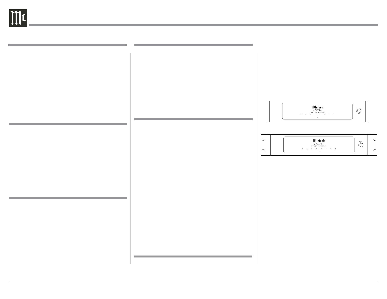
3. Included with the MI128 and located in the
Owner’s Manual Packet are two Side Rack Mount
Brackets and screw fasteners. Below are graphic
images of the MI128 with and without the Side
Rack Mounted Brackets attached. Refer to page 5
for installing the Side Rack Mount Brackets.
4. For the best performance and safety it is impor-
tant to always attach a single Loudspeaker with
an 8 Ohm or 4 Ohm impedance to the Channel
1 - Channel 8 output terminals. Refer to “How to
Connect” pages 8 thru 11.
Note: The impedance of a Loudspeaker actually var-
ies as the Loudspeaker reproduces different
frequencies. As a result, the nominal impedance
rating of the Loudspeaker (usually measured at
a midrange frequency) might not always agree
with the impedance of the Loudspeaker at low
frequencies where the greatest amount of power
is required. Contact the Loudspeaker Manufac-
turer for additional information about the actual
impedance of the Loudspeaker before connecting
it to the McIntosh MI128.
Your decision to own this McIntosh MI128 Eight
Channel Power Amplifier ranks you at the very top
among discriminating music listeners. You now have
“The Best.” The McIntosh dedication to “Quality,” is
assurance that you will receive many years of musical
enjoyment from this unit.
Please take a short time to read the information in
this manual. We want you to be as familiar as pos-
sible with all the features and functions of your new
McIntosh.
Copyright 2018 © by McIntosh Laboratory, Inc.
Table of Contents
Thank You
Please Take A Moment
Technical Assistance
If at any time you have questions about your McIntosh
product, contact your McIntosh Dealer who is familiar
with your McIntosh equipment and any other brands
that may be part of your system. If you or your Dealer
wish additional help concerning a suspected problem,
you can receive technical assistance for all McIntosh
products at: McIntosh Laboratory, Inc.
2 Chambers Street
Binghamton, New York 13903
Phone: 607-723-3512
Fax: 607-724-0549
Customer Service
If it is determined that your McIntosh product is in
need of repair, you can return it to your Dealer. You
can also return it to the McIntosh Laboratory Service
Department. For assistance on factory repair return
procedure, contact the McIntosh Service Department
at: McIntosh Laboratory, Inc.
2 Chambers Street
Binghamton, New York 13903
Phone: 607-723-3515
Fax: 607-723-1917
The serial number, purchase date and McIntosh Dealer
name are important to you for possible insurance
claim or future service. The spaces below have been
provided for you to record that information:
Serial Number: _______________________________
Purchase Date: _______________________________
Dealer Name: ________________________________
Important Safety Information is supplied in a separate document “Important Additional Operation Information Guide
Safety Instructions ..................................................... 2
(Separate Sheet) ................... Important Additional
Operation Information Guide
Thank You and Please Take a Moment ....................... 2
Technical Assistance and Customer Service .............. 2
Table of Contents ........................................................ 2
General Information ................................................... 2
Connector and Cable Information ..............................3
Introduction .................................................................3
Performance Features .................................................3
Dimensions .................................................................4
Installation ..................................................................5
Rear Panel Connections, Switches and Selection ....6-7
Output Terminals and How to Connect .................8-13
Front Panel Displays and Push-button ...................... 14
How to Operate ......................................................... 15
Photos ................................................................... 16 -17
Specifications ............................................................ 18
Packing Instruction ................................................... 19
1. For additional connection information, refer to the
owner’s manual(s) for any component(s) connected
to the MI128.
General Information
MI128 8 Channel Power Amplifier with
Side Rack Mount Brackets installed
MI128 4 Channel Power Amplifier
3
Power Control Connector
The MI128 Power Control Input receives an On/Off
signal from +5 to +12 volts. The Power Control Output
will in turn provide a +12 volt Output Signal with a
total current up to 50mA. An ad-
ditional connection is for controlling
the illumination of the MI128 Meter
Power Output Indicators. The 3.5mm
stereo mini phone plug connects to a
McIntosh Preamplifier or A/V Control Center Power
Control Output.
General Information, Connector and Cable Information, Introduction and Performance Features
Connector Information
Introduction
Performance Features
Power
Control
Meter
Illumination
Control
Ground
Now you can take advantage of traditional McIntosh
standards of excellence in the MI128 Power Amplifier.
The Eight Channel Power Amplifier produces high
power output per channel and will drive quality Loud-
speakers to a high level of performance. The MI128
reproduction is sonically transparent and absolutely
accurate. The McIntosh Sound is “The Sound of the
Music Itself.”
• Power Output
The MI128 consists of Eight Power Amplifier Chan-
nels, each capable of 120 watts into 8 ohm or 150
watts into 4 ohm Loudspeakers with distortion less
than 0.025%.
• Loudspeaker Guard
The McIntosh Loudspeaker Guard Circuit prevents the
amplifier from being over driven into clipping, with
its harsh distorted sound that can damage your valu-
able Loudspeakers.
Versatile Operation
The MI128 provides power amplification for up to
eight channels in a multi Zone Audio System.
• Unbalanced Inputs
There are eight Unbalanced Analog Audio Inputs for
all eight Power Amplifier Channels.
Digital Audio Inputs
The Digital Inputs decode PCM Signals from external
sources. The Optical Inputs process Digital Signals
from 32kHz to 192kHz with 24-Bit resolution.
5
. In the event the MI128 Channels over heat, due to
improper ventilation or Loudspeaker Impedance,
the protection circuits will activate. The Front
Panel Channel LED will change color and the audio
will be muted. Refer to page 13. When the MI128
has returned to a safe operating temperature, the
Channel(s) normal operation will resume.
6. If it becomes necessary to replace the Loudspeaker
Connection Plugs used on the MI128 Rear Panel,
order part number 31065800 from the McIntosh
Parts Department.
7. For additional information on the MI128 and
other McIntosh Products please visit the McIntosh
Website at www.mcintoshlabs.com.
• Sentry Monitor and Thermal Protection
McIntosh Sentry Monitor power output stage protec-
tion circuits ensure the MI128 will have a long and
trouble free operating life. Built-in Thermal Protection
circuits guard against overheating.
• Power Control
The McIntosh Power Control Circuit allows for remote
turn-on of the MI128 Power Amplifier from a McIn-
tosh A/V Control Center or Preamplifier for a single
or dual Zone System.
• Special Power Supply
A regulated Power Supply ensures stable noise free
operation even though the power line varies.
• LED Solid State Front Panel Illumination
The even Illumination of the Front Panel is accom-
plished by extra long life Light Emitting Diodes
(LEDs). The Metal and Glass Front Panel ensures the
pristine beauty of the MI128 will be retained for many
years.
4
Dimensions
The following dimensions can assist in determining
the best location for your MI128.
Dimensions
Rear View of the MI128
Side View of the MI128
Front View of the MI128
17-
1/2"
44.5cm
3-15/32"
8.8cm
4-5/16"
11.0cm
13-1/4"
33.7cm
18-1/2"
47.0cm
17-1/16"
43.3cm
.25"
.64cm
2.0"
5.0cm
13-19/32"
34.7cm
1-5/16"
3.4cm
3/16
"
.5cm
3-1/4"
8.2cm
Front View of the MI128 with Side Mount Brackets
19"
48.3cm
16-1/2"
41.9cm
5
Installation
Installation
The MI128 needs to be placed upright on its four feet.
It also can be custom installed. Remove the four feet
when it is custom installed and retain them with the
fastening screws for possible future use. The required
panel cutout, ventilation cutout and unit dimensions
are shown in the drawing on the right side of this
page.
It is necessary to provide adequate ventilation for
cool operation, ensuring long life for the MI128. Do
not install the MI128 above heat generating compo-
nents. When the MI128 is installed in a cabinet with
other components, use a ventilation fan to provide cool
operating temperature.
A custom cabinet installation needs to provide the
following minimum spacing for cool operation:
Allow at least 3 inches (7.6cm) above the top,
2 inches (5.08cm) below the bottom, 3 inches
(7.62cm) behind the rear panel and 2 inches
(5.08cm) on each side of the MI128, providing
airflow. Allow 2-1/2 inches (6.35 cm) in front of the
mounting
1
panel for clearance. Be sure to cut out a
ventilation hole in the mounting shelf according to
the dimensions in the drawing.
1
When the MI128 is installed together with other
McIntosh Components, check clearances on all
components before proceeding.
Cutout Opening for Custom Mounting
MI128 Front Panel
Custom Cabinet Cutout
Support
Shelf
Chassis
Spacers
MI128 Side View
in Custom Cabinet
MI128 Bottom View
in Custom Cabinet
Cabinet
Front
Panel
Opening
for Ventilation
Note: Center the cutout Horizontally
on the unit. For purposes of
clarity, the above illustration
is not drawn to scale.
Cutout Opening for Ventilation
16-7/8"
42.8cm
3-1/4"
8.2cm
25/32
"
2.0cm
29/32
"
2.4cm
3"
7.6cm
11-19/32"
29.7cm
15"
38.1cm
Cutout Opening
for Ventilation
10-
9/16
"
26.9cm
14-
7/16
"
36.2cm
3"
7.6cm
Installation of Side Rack Mount Brackets
Remove two
Screws from
the Chassis
Sidewall
and save
them
Front Panel
Side Panel
Side Rack
Mounting
Bracket
Supplied
Screws
Supplied
Screws
Front Panel
Side Panel
When desired, to install MI128 Side Rack Mounting
Brackets, follow the steps below for one side at a time:
1. Refer to figure A to remove the two side screws and
save them for possible future use.
2. Position the Side Rack Mounting Bracket as illustrated
in figure B. Then attach the Bracket to the Front and
Side Panel of the MI128, using the screws supplied
with the Bracket.
3. Perform steps 1 and 2 to mount the second Bracket to
the other side of the MI128.
Figure A
Figure B
6
Audio Input Selection for each Power Am-
plifier Channel
Each Channel of the MI128 allows selection of differ-
ent Audio Signal Inputs to be Amplified after selected
via the two switches.
The first switch LOCAL/BUS selects between
the specific Channel Unbalanced Input Jack or BUS
which allows selection of the BUS Switch (1, 2, D1 or
D2).
LINE UNBALANCED INPUT
(For Left and Right Channels)
The BUS Switch allows selection of the following:
BUS 1 - Unbalanced Input Jack (L or R) dependent by
its Channel Type.
BUS 2 - Unbalanced Input Jack (L or R) dependent by
its Channel Type
DIG 1 - Coaxial or Optical Digital Input Connector
DIG 2 - Coaxial or Optical Digital Input Connector
BUS Input Switch
Channels 1- 8
-1 (BUS 1)
-2 (BUS 2)
- D1 (Digital Bus 1)
- D2 (Digital Bus 2)
BUS 2 UNBALANCED INPUT
(For Left and Right Channels)
BUS 1 UNBALANCED INPUT
(For Left and Right Channels)
DIGITAL BUS 1 COAXIAL INPUT
(Contains Both Channel Signals)
DIGITAL BUS 1 OPTICAL INPUT
(Contains Both Channel Signals)
DIGITAL BUS 2 COAXIAL INPUT
(Contains Both Channel Signals)
DIGITAL BUS 2 OPTICAL INPUT
(Both Channel Signals)
7
Audio Input(s) Signal Selection
Connections for
Loudspeakers (1-8)
Channels 1-8
Power Ampliers
Channels Mode Switch
1-2, 3-4, 5-6, 7-8
- STEREO
- MONO
Channels Input Switch
1-8
- LINE
- BUS
8
the insulation is removed from the cable
end. The acceptable diameter of the copper
stands size is 0.100 inches (2.54 mm) so it
will fit the into opening on the MI128 Con-
nection Plug.
B. If desired, the twisted ends can be tinned
with solder to keep the strands together.
3. Adjust the two top screws of
the Loudspeaker Connection
Plug to provide a sufcient
opening size so the bare wire
will t into the connector.
Refer to gure 2.
4. Insert the Loudspeaker
Hookup Cable bare
wire end into the
Connection Plug
opening. Refer to
gure 3.
5. With the Hookup Ca-
ble insulation ush
with the Loudspeak-
er Connection Plug
opening, now rotate
the two top screws to
secure the Hookup
Cable with the plug.
Refer to gure 4.
6. Now complete the remaining Loudspeaker Con-
nection Plugs and the Loudspeaker Hookup Cables
WARNING: The MI128 Chassis Loudspeaker Con-
nection Socket Pins present a risk of
electric shock when the Amplifier is
On. For additional assistance on using
Loudspeaker Connections Plugs con-
tact your McIntosh Dealer or McIntosh
Technical Support.
.
When connecting the Loudspeaker Hookup Cables to
the MI128 using the supplied Loudspeaker
Connection Plugs. Refer to figure 1.
1. When connecting Loudspeakers to the
MI128 it is very important to use cables
of adequate size, so there is little to no
power loss in the cables. The size is
specified in Gauge Numbers or AWG (American
Wire Gauge). The smaller the Gauge number, the
larger the wire size:
Loudspeaker Cable Distance vs Wire Gauge Guide
Loudspeaker
Impedance
25 feet
(7.62 meters)
or less
50 feet
(15.24 meters)
or less
100 feet
(30.48 meters)
or less
4 Ohms
14AWG 12AWG 10AWG
8 Ohms
16AWG 14AWG 12AWG
This McIntosh MI128 Power Amplifier is designed
for Loudspeakers with an impedance of 4 ohms or
8 ohms. Connect a single Loudspeaker only to each
Channel Output Terminal.
2. Prepare the Loudspeaker Hookup Cable for attach-
ment to the MI128 Power Amplifier:
Bare wire cable ends:
Carefully remove sufficient insulation from the
cable
ends,
refer to
figures
1, 2 &
3. If
the cable is stranded, carefully twist the strands
together as tightly as possible.
Notes: A. If the Loudspeaker Cable used is greater
in size than 12AWG, it can be used by
removing some of the copper strands after
How to Connect from a Multichannel Zone
Preamplifier
Caution: Do not connect the AC Power Cord to the MI128
Rear Panel until after the Loudspeaker Con-
nections are made. Failure to observe this could
result in Electric Shock.
The connection instructions below, together with the
MI128 Connection Diagram located on the separate
folded sheet “Mc1B, is an example of a typical Mul-
tichannel System. Your system may vary from this,
however the actual components would be connected in
a similar manner. For additional information refer to
“Connector and Cable Information” on page 3.
1. For Remote Power Control, connect a power control
cable from the A/V Control Center Power Control
Trigger/Output 2 to the Amplifier POWER CON-
TROL INPUT.
Note: When the Power Control Cable is connected
between the MI128 and an A/V Control Center,
the AUTO OFF Signal Sensing Circuitry is
automatically disabled.
2. Optionally, connect the MI128 POWER CON-
TROL OUT using a power control cable to the first
Loudspeaker and then connect the first Loud-
speaker Power Control Out to the Power Control In
on the next Loudspeaker. Connect the remaining
Loudspeakers in the same way.
3. Connect unbalanced cables from the A/V Control
Center Analog Audio Out Zone 2 (Left and Right
Channel) to the MI128 BUS 1 INPUTS, making
sure to match up channel designations.
4. Connect unbalanced cables from the A/V Control
Center Analog Audio Out Zone 3 (Left and Right
Channel) to the MI128 BUS 2 INPUTS, making
sure to match up channel designations.
Figure 2
Figure 3 Figure 4
0.100 inches
2.54 mm
0.5 inches
12.7 mm
Output Plug Connection
Figure 1
Cable Insulation
Loudspeaker
Connection
Plug
Figure 4
Cable Insulation
Cable Bare Wire
Loudspeaker
Connection
Plug
Figure 3
Figure 2
Openings
Screws
9
5. Place the CHANNEL 1/2 and 3/4 Input Selector
Switches to the “1” Position.
6. Place the CHANNEL 5/6 and 7/8 Input Selector
Switches to the “2” Position.
7. Place the Analog Audio/Digital Audio CHANNEL
1/2, 3/4, 5/6 and 7/8 Input Selector Switches to the
“BUS” Position.
This McIntosh MI128 Power Amplifier is designed
for Loudspeakers with an impedance of 4 ohms or
8 ohms. Connect a single Loudspeaker only to each
Channel Output Terminals.
8. With the Loudspeaker Hookup Cable attached to
the Loudspeaker Connection Plug, insert the Plug
End into the correct MI128 Rear Panel Chassis
Loudspeaker Socket. Then connect the opposite
end of the Loudspeaker Hookup Cable to the
Loudspeaker Connection Terminals. Make sure to
match up the MI128 Negative and Positive Output
Connection on the Plug Connector, with the Loud-
speaker Negative and Positive Input Connections.
WARNING: Loudspeaker terminals are hazard-
ous live and present a risk of electric
shock. For additional instruction on
making Loudspeaker Connections
contact your McIntosh Dealer or
McIntosh Technical Support.
9. After all the connections have been completed,
connect the MI128 power cord to an active AC
outlet.
How to Connect from a Multichannel Zone Preamplifier
10
the insulation is removed from the cable
end. The acceptable diameter of the copper
stands size is 0.100 inches (2.54 mm) so it
will fit the into opening on the MI128 Con-
nection Plug.
B. If desired, the twisted ends can be tinned
with solder to keep the strands together.
3. Adjust the two top screws of
the Loudspeaker Connection
Plug to provide a sufcient
opening size so the bare wire
will t into the connector.
Refer to gure 2.
4. Insert the Loudspeaker
Hookup Cable bare
wire end into the
Connection Plug
opening. Refer to
gure 3.
5. With the Hookup Ca-
ble insulation ush
with the Loudspeaker
Connection Plug
opening, now rotate
the two top screws to
secure the Hookup
Cable with the plug.
Refer to gure 4.
6. Now complete the remaining Loudspeaker Con-
nection Plugs and the Loudspeaker Hookup Cables
WARNING: The MI128 Chassis Loudspeaker Con-
nection Socket Pins present a risk of
electric shock when the Amplifier is
On. For additional assistance on using
Loudspeaker Connections Plugs con-
tact your McIntosh Dealer or McIntosh
Technical Support.
.
When connecting the Loudspeaker Hookup Cables to
the MI128 using the supplied Loudspeaker
Connection Plugs. Refer to figure 1.
1. When connecting Loudspeakers to the
MI128 it is very important to use cables
of adequate size, so there is little to no
power loss in the cables. The size is
specified in Gauge Numbers or AWG (American
Wire Gauge). The smaller the Gauge number, the
larger the wire size:
Loudspeaker Cable Distance vs Wire Gauge Guide
Loudspeaker
Impedance
25 feet
(7.62 meters)
or less
50 feet
(15.24 meters)
or less
100 feet
(30.48 meters)
or less
4 Ohms
14AWG 12AWG 10AWG
8 Ohms
16AWG 14AWG 12AWG
This McIntosh MI128 Power Amplifier is designed
for Loudspeakers with an impedance of 4 ohms or
8 ohms. Connect a single Loudspeaker only to each
Channel Output Terminal.
2. Prepare the Loudspeaker Hookup Cable for attach-
ment to the MI128 Power Amplifier:
Bare wire cable ends:
Carefully remove sufficient insulation from the
cable
ends,
refer to
figures
1, 2 &
3. If
the cable is stranded, carefully twist the strands
together as tightly as possible.
Notes: A. If the Loudspeaker Cable used is greater
in size than 12AWG, it can be used by
removing some of the copper strands after
How to Connect for Eight Zones
Caution: Do not connect the AC Power Cord to the MI128
Rear Panel until after the Loudspeaker Con-
nections are made. Failure to observe this could
result in Electric Shock.
The connection instructions below, together with the
MI128 Connection Diagram located on the separate
folded sheet “Mc1C, is an example of a typical Mul-
tichannel System. Your system may vary from this,
however the actual components would be connected in
a similar manner. For additional information refer to
“Connector and Cable Information” on page 3.
1. For Power Remote Control of the MI128, connec-
tions from the Audio Source Components Power
Control Connection(s) can provide that operation.
Note: When the Power Control Cable is connected
between the MI128 and an Audio Source Com-
ponent, the AUTO OFF Sensing Circuitry of
the MI128 is disabled.
2. Connect a Power Control Cable from the Stream-
ing Audio Player Trigger (Power Control) Output
connector to the FM/AM Tuner Power Control IN
(Input) Connector.
3. Connect a second Power Control Cable from the
FM/AM Tuner Power Control OUT (Output) con-
nector to the MI128 POWER CONTROL INput
Connector.
4. Optionally, connect the MI128 POWER CON-
TROL OUTput if any of the Loudspeaker connect-
ed to the MI128 have Power Control In connectors.
5. Using a Digital Optical Cable connect the Stream-
ing Audio Player Audio Output Optical Connector
to the MI128 DIGital 1 Optical Input Connector.
6. Connect a Coaxial Digital Cable from the FM/AM
Tuner Digital Coaxial Output Connector to the
MI128 DIGital 2 Coaxial Input Connector.
Figure 2
Figure 3 Figure 4
0.100 inches
2.54 mm
0.5 inches
12.7 mm
Output Plug Connection
Figure 1
Cable Insulation
Loudspeaker
Connection
Plug
Figure 4
Cable Insulation
Cable Bare Wire
Loudspeaker
Connection
Plug
Figure 3
Figure 2
Openings
Screws
11
How to Connect for Eight Zones
7. Place the CHANNEL 1/2 and 3/4 Digital Input
Selector Switches to the “D1” Position.
8. Place the CHANNEL 5/6 and 7/8 Digital Input
Selector Switches to the “D2” Position.
9. Place the CHANNEL 1/2, 3/4, 5/6 and 7/8 Mode
Switches in the “MONO” Position.
This McIntosh MI128 Power Amplifier is designed
for Loudspeakers with an impedance of 4 ohms or
8 ohms. Connect a single Loudspeaker only to each
Channel Output Terminals.
10. With the Loudspeaker Hookup Cable attached to
the Loudspeaker Connection Plug, insert the Plug
End into the correct MI128 Rear Panel Chassis
Loudspeaker Socket. Then connect the opposite
end of the Loudspeaker Hookup Cable to the
Loudspeaker Connection Terminals. Make sure to
match up the MI128 Negative and Positive Output
Connection on the Plug Connector, with the Loud-
speaker Negative and Positive Input Connections.
WARNING: Loudspeaker terminals are hazard-
ous live and present a risk of electric
shock. For additional instruction on
making Loudspeaker Connections
contact your McIntosh Dealer or
McIntosh Technical Support.
11. After all the connections have been completed,
connect the MI128 power cord to an active AC
outlet.
12
Front Panel Displays and Switch
LED Standby
Power On
Indicator
LED indicates various Channel 4
Circuitry Functions
POWER Push-Button switches
AC Power On or Off
LED indicates various Channel 3
Circuitry Functions
LED indicates various Channel 2
Circuitry Functions
LED indicates various Channel 1
Circuitry Functions
LED indicates various Channel 5
Circuitry Functions
LED indicates various Channel 6
Circuitry Functions
LED indicates various Channel 7
Circuitry Functions
LED indicates various Channel 8
Circuitry Functions
13
When the LOCAL-BUS Switch is placed in the
BUS Position the selection of the Audio Signal Input
for the Power Amplifier Channels (1&2,
3&4, 5&6 and 7&8) is determined by the
1-2-D1-D2” Selector Switch. Refer to
figure 23.
The 1 and 2 Selector Switch Positions
are for the Analog Signals from the BUS1/BUS2 Left
and Right Input Jacks for the Power Amplifier Chan-
nels.
The D1 Switch Position allows the Digital Au-
dio Signals from the DIG1 Optical or Coaxial Input
Connector to be available for the Power Amplifier
Channels. The D2 Switch Position performs the same
functions from the DIG2 Optical or Coaxial Input
Connector.
Mode Selector
Each pair of the eight Power Amplifier Channels
(1&2, 3&4, 5&6 and 7&8) have a Mode Switch located
on the MI128 Rear Panel for STEREO or MONO
Mode of Operation. Refer to
figure 24. The Mode Switch
affects all three of the Ana-
log Input Pairs. It also affects the Digital Optical or
Coaxial Input Audio Signal.
MI128 Channel Operation Functions
LED COLOR
Functional Status
LED not
Illuminated
Indicates when the Channel is OFF
Green
Indicates when the Channel is ON with an
Audio Signal Present and Normal Operation for
the Channel exists
Amber
Indicates when maximum Power Output for the
Channel has occured with prevention of Audio
Clipping
Red
Indicates current limit or short circuit for the
Channel Loudspeaker Output Connection
Volume Controls
Each of the eight MI128 Power Amplifier Channels
have a VOLume Control to
allow altering the incoming
audio signal volume level.
Refer to figure 21.
Input Selector
Each pair of the eight Power Amplifier Channels
(1&2, 3&4, 5&6 and 7&8) have switches located on
the MI128 Rear Panel for selection of the Input Source
Signal and determine the Audio Signal Mode. Refer to
pages 6 and 7 for additional information.
The LOCAL-BUS Switch determines for the
Power Amplifier Channels (1&2, 3&4, 5&6 and 7&8)
if the Audio Signal will be from the
Unbalanced Left and Right Input
Jacks or from the BUS Analog/Digi-
tal Input Connectors. Refer to figure
22.
Power On
The LED STANDBY/ON Indicator illuminates to
indicate the MI128 is connected to AC
Power. To switch ON the MI128, press
the POWER Push-button on the Front
Panel or switch On the Audio Source
Component providing there is a Power
Control Cable Connection to the MI128.
Refer to figure 20.
Notes: 1. It will take about 6 seconds for initialization of
the internal circuitry to take place on the MI128
when switched On.
2. There must be a power control connection be-
tween the MI128 and the Audio Source Compo-
nent in order for the Remote Control Operation
Power ON/OFF to function.
3. When the MI128 is receiving a Power Control
ON Signal, the Front Panel POWER Push-But-
ton becomes inactive.
Auto Off Function
The MI128 incorporates Power Save Circuitry to
automatically place the MI128 into the power saving
Standby Mode approximately 10 minutes after there
has been an absence of an audio input signal on all
eight channels.
When there is a Power Control Connection be-
tween the MI128 and a Preamplifier or Source Com-
ponent, the AUTO OFF Function is bypassed.
Channel Operational Indication
The MI128 Front Panel has eight LEDs. The LEDs
indicate the current functioning status for each of the
eight channels.
How to Operate
How to Operate
Figure 20
Figure 21
Figure 22
Figure 23
Figure 24
14
Power Output
Minimum sine wave continuous average power output
per channel, all channels operating is:
120 watts into a 8 ohm load
150 watts into a 4 ohm ohm load
Output Load Impedance
8 and 4 ohms
Rated Power Band
20Hz to 20,000Hz
Total Harmonic Distortion
0.05% maximum harmonic distortion at any power
level from 250 milliwatts to rated power, 20Hz to
20,000Hz
Dynamic Headroom
2.1dB, 8 ohm load
3.3dB, 4 ohm load
Frequency Response
+0, -0.5dB from 20Hz to 20,000Hz
Input Sensitivity (for rated output)
1.6 Volt Unbalanced (8 ohm Loudspeaker)
1.3 Volt Unbalanced (4 ohm Loudspeaker)
Signal To Noise Ratio (A-Weighted)
85dB (95dB below rated output)
Intermodulation Distortion
0.2% maximum, if the instantaneous peak power
output does not exceed twice the rated power output
or less per channel with all channels operating for any
combination of frequencies from 20Hz to 20,000Hz
Wide Band Damping Factor
Greater than 65, at 8 ohms
Greater than 32, at 4 ohms
Input Impedance
26,000 ohms Unbalanced
Volt age Gai n
29dB
Power Control Input
5-15VDC, less than 1mA
Power Control Output
12VDC, 50mA maximum total
Power Requirements
100 - 240Volts, 50/60Hz at 10 Amps
Standby: less than 0.5 watt
Overall Dimensions
Width is 17-1/2 inches (44.5cm)
Width with Side Mount Brackets attached is
19 inches (48.3cm)
Height is 4-5/16 inches (11.0cm) including feet
Depth is 21 inches (53.3cm) including the Front Panel
and Cables
Weight
22 pounds (10 kg) net, 38.4 pounds (17.4 kg) in ship-
ping carton
Shipping Carton Dimensions
Width is 26-1/2 inches (67.3cm)
Height is 11-3/4 inches (29.9cm)
Depth is 24-1/4 inches (61.6cm)
Specications
Specications
15
Packing Instructions
In the event it is necessary to repack the equipment for
shipment, the equipment must be packed exactly as
shown below. It is very important that the four plas-
tic feet are attached to the bottom of the equipment.
This will ensure the proper equipment location on the
bottom pad. Failure to do this will result in shipping
damage.
Use the original shipping carton and interior parts
only if they are all in good serviceable condition. If
a shipping carton or any of the interior part(s) are
needed, please call or write Customer Service Depart-
ment of McIntosh Laboratory. Refer to page 2. Please
see the Part List for the correct part numbers.
Quantity Part Number Description
1 033838 Shipping carton only
2 033837 End cap
1 033836 Inside carton only
1 033725 Top pad
1 034576 Bottom pad
1 034592 Filler pad
2 034446 Foam plug
4 017937 Plastic foot
4 400159 #10-32 x 3/4” screw
4 404080 #10 Flat washer
FOAM PLUG
The continuous improvement of its products is the
policy of McIntosh Laboratory Incorporated who
reserve the right to improve design without notice.
Printed in the U.S.A.
McIntosh Laboratory, Inc.
2 Chambers Street
Binghamton, NY 13903
www.mcintoshlabs.com
McIntosh Part No. 04192700
  • Page 1 1
  • Page 2 2
  • Page 3 3
  • Page 4 4
  • Page 5 5
  • Page 6 6
  • Page 7 7
  • Page 8 8
  • Page 9 9
  • Page 10 10
  • Page 11 11
  • Page 12 12
  • Page 13 13
  • Page 14 14
  • Page 15 15
  • Page 16 16

McIntosh MI128 Owner's manual

Type
Owner's manual

McIntosh MI128 is an 8-channel power amplifier capable of delivering high-fidelity audio to multiple zones or speakers in a home audio system. With 120 watts of power per channel into 8 ohms or 150 watts into 4 ohms, it can drive a variety of speaker setups with clarity and precision. The MI128 features unbalanced analog audio inputs, digital inputs for PCM signals, a loudspeaker guard to prevent distortion, and thermal protection circuitry to ensure safe operation.

Ask a question and I''ll find the answer in the document

Finding information in a document is now easier with AI