Page is loading ...

March
1988
FORM:
OM-1
558
MODEL
MU-812HR
MTF-825H
R
MTr-912HF
MU-925
H
F
MTI-912VHF
MU-925VH
F
FilL!
COpy
RETURN
TO
FOLDER
OWNERS
MANUAL
IMPORTANT
Read
and
understand
the
entire
contents
of
both
this
Miller
Electric
Mfg.Co.
manual
and
the
power
source
manual
used
with
this
unit,
with
special
AMe~G~u~tr~1
CornQ~n~
emphasis
on
the
safety
material
throughout
both
manuals,
before
in-
p.o.
Box
1079
stalling,
operating,
or
maintaining
this
equipment.
This
unit
and
these
Appleton,
WI
54912
USA
instructions
are
for
use
only
by
persons
trained
and
experienced
in
the
Tel.
414-734-9821
safe
operation
of
welding equipment.
Do
not
allow
untrained
persons
to
install,
operate,
or
maintain
this
unit.
Contact
your
distributor
if
you
do
not
fully
understand
these
instructions.
Millerfi
Effective
With
Style
No.
JJ-23
PRINTED
IN
U.S.A.
ADDITONAL
COPY
PRICE
30
CENTS
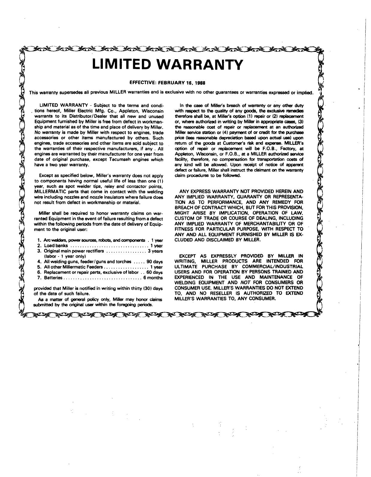
LIMITED
WARRANTY
EFFECTIVE:
FEBRUARY
16.
1988
This
warranty
supersedes
all
previous
MILLER
warranties
and
is
exclusive
with
no
other
guarantees
or
warranties
expressed
or
implied.
LIMITED
WARRANTY
-
Subject
to
the
terms
and
condi-
In
the
case
of
Millers
breach
of
warranty
or
any
other
duty
tions
hereof,
Miller
Electric
Mfg.
Co.,
Appleton,
Wisconsin
with
respect
to
the
quality
of
any
goods,
the
exdusive
remedies
warrants
to
its
Distributor/Dealer
that
all
new
end
unused
therefore
shall
be,
at
Millers
option
(1)
repair
or
(2)
replacement
Equipment
furnished
by
Miller
is
free
from
defect
in
workman-
or,
where
authorized
in
writing
by
Miller
in
appropriate
cases,
(3)
ship
and
material
as
of
the
time
and
place
of
delivery
by
Miller.
the
reasonable
cost
of
repair
or
replacement
at
an
authorized
No
warranty
is
made
by
Miller
with
respect
to
engines,
trade
Miller
service
station
or
(4)
payment
of
or
credit
for
the
purchase
accessories
or
other
items
manufactured
by
others.
Such
price
(less
reasonable
depreciation
based
upon
actual-use)
upon
engines,
trade
accessories
and
other items
are
sold
subject
to
return
of
the
goods
at
Customers
risk
and
expense.
MILLERs
the
warranties
of
their
respective
manufacturers,
if
any
All
option
of
repair
or
replacement
will
be
F.O.B.,
Factory,
at
engines
are
warranted
by
their
manufacturer
for
one
year
from
Appleton,
Wisconsin,
or
F.O.B.,
at
a
MILLER
authorized
sennce
date
of
original
purchase,
except
Tecumseh
engines
which
facility,
therefore,
no
compensation
for
transportation
costs
of
have
a
two
year
warranty.
any
kind
will
be
allowed.
Upon
receipt
of
notice
of
apparent
defect
or
failure,
Miller
shall
instruct
the
claimant
on
the
warranty
Except
as
specified
below,
Millers
warranty
does
not
apply
claim
procedures
to
be
followed.
to
components
having
normal
useful
life
of
less
than
one
(1)
year,
such
as
spot
welder
tips,
relay
and
contactor
points,
MILLERMATIC
parts
that
come
in
contact
with
the
welding
ANY
EXPRESS
WARRANTY
NOT
PROVIDED
HEREIN
AND
wire
including
nozzles
and
nozzle
insulators
where
failure
does
ANY
IMPLIED
WARRANTY,
GUARANTY
OR
REPRESENTA
~
not
result
from
defect
in
workmanship
or
material.
lION
AS
TO
PERFORMANCE,
AND
ANY
REMEDY
FOR
BREACH
OF
CONTRACT
WHICH,
BUT
FOR
THIS
PROVISION,
~
Miller
shall
be
required
to
honor
warranty
claims
on
war-
MIGHT
ARISE
BY
IMPLICATION,
OPERATION
OF
LAW,
~j~
ranted
Equipment
in
the
event
of
failure
resulting
from
a
defect
CUSTOM
OF
TRADE
OR
COURSE
OF
DEALING,
INCLUDING
9
within
the
following
periods
from
the
date
of
delivery
of
Equip-
ANY
IMPUED
WARRANTY
OF
MERCHANTABIUTY
OR
OF
ment
to
the
original
user:
FITNESS
FOR
PARTICULAR
PURPOSE,
WITH
RESPECT
TO
ANY
AND
ALL
EQUIPMENT
FURNISHED
BY
MILLER
IS
EX
j~
1.
Arc
waldera,
power
sources,
robots,
and
components
.
1
year
CLUDEO
AND
DISCLAIMED
BY
MILLER.
2.
Loadbanks
lyear
j
3.
Original
main
power
rectifiers
3
years
(labor
-
1
year
only)
EXCEPT
AS
EXPRESSLY
PROVIDED
BY
MILLER
IN
]
4.
All
welding
guns,
feeder/guns
and
torches
90
days
WRITING,
MILLER
PRODUCTS
ARE
INTENDED
FOR
~
5.
All
other
Millermatic
Feeders
1
year
ULTIMATE
PURCHASE
BY
COMMERCIAL/INDUSTRIAL
~
6.
Replacement
or
repair
parts,
exclusive
of
labor
..
60
days
USERS
AND
FOR OPERATION
BY
PERSONS
TRAINED
AND
~
7.
Batteries
6
months
EXPERIENCED
IN
THE
USE
AND
MAINTENANCE
OF
WELDING
EQUIPMENT
AND
NOT
FOR
CONSUMERS
OR
~4J
provided
that
Miller
is
notified
in
writing
within
thirty
(30)
days
CONSUMER
USE.
MILLERS
WARRANTIES
DO
NOT
EXTEND
!~
of
the
date
of
such
failure.
TO,
AND
NO
RESELLER
IS
AUTHORIZED
TO
EXTEND
As
a
matter
of
general
policy
only,
Miller
may
honor
claims
MILLERS
WARRANTIES
TO,
ANY
CONSUMER.
(1
submitted
by
the
original
user
within
the
foregoing
periods.
-
t,
.-
.
.-
~...
.
.
-

ing.
Do
not
weld
near
combustible
material.
Watch
for
fire,
and
keep
a
fire
extinguisher
near
by.
For
additional
information,
refer
to
NFPA
Stan
dard
51
B,
Fire
Prevention
in
Use
of
Cutting
and
Welding
Processes,
available
from
the
National
Fire
Protec~tion
Association,
Batterymarch
Park,
Quincy,
MA
02269.
1
-5.
PROTECT
COMPRESSED
GAS
CYLINDERS
Since
gas
cylinders
are
normally
part
of
the
welding
pro
cess,
be
sure
to
treat
them
carefully.
a.
Protect
compressed
gas
cylinders
from
excessive
heat,
mechanical
shocks,
and
arcs.
Install
and
secure
cylinders
so
that
they
cannot
fall
or
tip
over
by
fastening
them
to
a
mounting
bracket,
wall,
or
other
stationary
support.
Keep
cylinders
away
from
any
welding
or
other
electrical
circuits.
Never
allow
a
welding
electrode
to
touch
any
cylinder.
WARNING
SECTION
1
-
SAFETY
RULES
_________
UNSAFE
PROCEDURES
OR
PRAC-
1
-3.
PROTECT
EYES
AND
SKIN
FROM
ARC
TICES
can
cause
serious
personal
injury
or
death.
RAYS;
PROTECT
EARS
FROM
NOISE
Read,
understand,
and
follow
ALL
of
these
safety
ru/es
before
installing,
operating,
or
servicing
this,
Arc
rays
from
the
welding
process
produce
intense
heat
equipment.
and
strong
ultraviolet
rays
that
can
burn
eyes
and
skin.
Be
sure
that
all
end
users
of
this
equipment,
the
Noise
from
some
processes
can
damage
hearing.
operator
and
helpers,
read
and
understand
these
safety
rules.
a.
Wear
a
welding
helmet
fitted
with
a
proper
filter
-
lens
(see
ANSI
Z49.1
for
detailed
information).
1
-
1.
PREVENT
ELECTRIC
SHOCK
b.
Use
protective
screens
or
barriers
to
protect
Touching
live
electrical
parts
can
cause
severe
burns
to
others
from
flash
and
glare.
the
body
or
fatal
shock.
Severity
of
e!ectrical
shock
is
determined
by
the
path
and
amount
of
current
through
c.
Wear
protective
clothing
and
foot
protection.
the
body.
Therefore:
d.
Always
wear
safety
glasses
or
safety
goggles
in
a
a.
Do
not
touch
live
electrical
parts,
work
area.
b.
Do
not
work
in
wet
or
damp
areas.
1
-
4.
PREVENT
FIRES
AND
BURNS
c.
Wear
dry
insulating
gloves
and
body
protection.
The
hot
workpiece,
hot
equipment,
other
hot
metal,
spatter,
and
arc
sparks
can
cause
fires
and
burns.
d.
Disconnect
all
power
before
installing
or
servic
ing
this
equipment.
a.
Wear
correct
eye,
face,
and
body
protection
in
the
work
area.
e.
Turn
off
all
equipment
when
not
in
use.
b.
Allow
work
and
equipment
to
cool
before
harodl
f.
Properly
install
and
ground
the
welding
power
source
according
to
its
Owners
Manual
and
all
applicable
codes.
c.
g.
Do
not
use
worn
or
damaged
cables
or
cables
d.
that
are
too
small
or
poorly
spliced.
-
h.
Do
not
wrap
cables
around
your
body.
e.
i.
Do
not
touch
electrode
and
any
grounded
object
or
circuit
at
the
same
time.
j.
Use
only
well-maintained
equipment.
Repair
or
replace
damaged
parts
at
once.
1
-2.
PROVIDE
PROTECTION
FROM
FUMES
AND
GASES
Breathing
welding
fumes
and
gases
can
be
hazardous
to
your
health.
a.
Keep
your
head
out
of
the
fumes.
b.
b.
Use
adequate
ventilation
in
the
work
area
to
keep
fumes
and
gases
from
your
breathing
zone
and
the
general
work
area.
C.
c.
If
ventilation
is
inadequate,
use
an
approved
breathing
device.
d.
d.
Read
the
Material
Safety
Data
Sheets
(MSDSs)
and
the
manufacturers
instructions
for
any
materials
used.
OM-15513
Page
1

1
-6.
PROVIDE
PROTECTION
FOR
SPECIAL
SITUATIONS
a.
Do
not
weld
or
cut
containers
or
materials
which
have
held
or
been
in
contact
with
hazardous
substances
unless
they
are
properly
cleaned
and
inspected.
b.
Do
not
weld
or
cut
painted
or
plated
parts
unless
special
ventilation
is
provided
to
remove
highly
toxic
fumes
or
gases.
c.
Since
welding
can
affect
pacemakers,
keep
all
pacemaker
wearers
out
of
the
work
area.
Have
them
consult
a
doctor
before
coming
near
a
welding
operation.
1
-7.
PROVIDE
PROPER
EQUIPMENT
MAINTENANCE
Improperly
maintained
equipment
can
result
in
poor
work,
but
most
importantly
it
can
cause
physical
injury
or
death
through
fires
or
electrical
shock.
Therefore:
a.
Always
have
qualified
personnel
perform
the
in
stallation,
troubleshooting,
and
maintenance
work.
Do
not
perform
any
electrical
work
unless
you
are
fully
qualified.
b.
Before
performing
any
maintenance
work
inside
a
power
supply,
disconnect
the
power
supply
form
the
electrical
power
source.
c.
Maintain
cables,
grounding
wire,
connections,
power
cord,
and
power
supply
in
safe
working
order.
Do
not
operate
any
equipment
in
ques
tionable
condition.
d.
Do
not
abuse
any
equipment
or
accessories.
Keep
equipment
away
from
heat
sources
such
as
furnaces,
wet
conditions
such
as
water
puddles,
oil
or
grease,
corrosive
atmospheres,
and
incle
ment
weather.
e.
Keep
all
safety
devices,
guards,
panels,
and
covers
in
position
and
in
good
repair.
f.
Use
equipment
for
its
intended
purpose.
Do
not
modify
it
in
any
manner.
1
-8.
ADDITIONAL
SAFETY
INFORMATION
For
more
information
on
safe
practices
for
setting
up
and
operating
electric
welding
and
cutting
equipment
and
on
good
working
habits,
ask
your
welding
equip
ment
supplier.
The
following
publications,
which
are
available
from
the
American
Welding
Society,
550
N.W.
LeJuene
Rd.,
Miami,
FL
33126,
are
recommend
ed
to
you:
a.
Safety
in
Welding
and
Cutting
-
AWS
Z49.1
(ANSI)
b.
Recommended
Safe
Practices
for
Gas-Shielded
Arc
Welding
-
AWS
A6.1
c.
Recommended
Safe
Practices
for
the
Prepara
tion
for
Welding
and
Cutting
of
Containers
and
Piping
That
Have
Held
Hazardous
Substances
-
AWS
F4.1
d.
NFPA
Standard
51
B,
Fire
Prevention
in
Use
of
Cutting
and
Welding
Processes,
available
from
the
National
Fire
Protection
Association,
Bat
terymarch
Park,
Quincy,
MA
02269.
e.
NFPA
Standard
70,
National
Electrical
Code,
available
from
the
National
Fire
Protection
Association,
Batterymarch
Park,
Quincy,
MA
02269.
f.
ANSI
Standard
Z87.1,
Safe
Practice
for
Oc
cupation
and
Educational
Eye
and
Face
Protec
tion,
available
from
the
American
National
Standards
Institute,
1430
Broadway,
New
York,
NY
10018.
g.
OSHA
Standard
29
CFR,
Part
1910,
Subpart
Q,
Welding,
Cutting,
and
Brazing,
available
from
the
Superintendent
of
Documents,
U.S.
Govern
ment
Printing
Office,
Washington,
DC
20402.
h.
CSA
Standard
Wi
17.2,
Code
for
Safety
in
Welding
and
Cutting,
available
from
the
Cana
dian
Standards
Association,
178
Rexdale
Blvd.,
Rexdale,
Ontario,
Canada
M9W
1
R3.
i.
See
also
the
Standards
Booklet
Index
in
the
welding
power
source
Owners
Manual.
OM-1
558
Page
2

SECTION
2-
INTRODUCTION
Ampere
Rating
at
100%
Duty
Cycle
DCEN;
ACHF
Tungsten
Size
Capacity
Cable
Length
12.5
ft.
(3.8
m)
Torch
Body
Length:
8.1
in.
(206.0
mm)
Cooling
Method
Wei
t
g
Net
2
lbs.
(0.9
kg)
Ship
2.5
lbs.
(1.1
kg)
80
Amperes
With
Argon*
Handle
Diameter:
0.75
in.
(19.0
mm)
HR
.020
thru
3/32
in.
(0.5
thru
25
ft.
(7.6
m)
Weight:
2.0
oz.
(57.0
g}
Air
4.5
lbs.
(2.0
kg)
5.0
lbs.
(2.3
kg)
HF
2.4
mm)
12.5
ft.
Length:
2
lbs.
3
lbs.
VHF
(3.8
m)
8.0
in.
(203.0
mm)
(0.9
kg)
(1.1
kg)
90
Amperes
With
Argon*
Handle
Diamter:
0.75
in.
(19.0
mm)
HF
25
ft.
Weight:
4.5
lbs.
5.0
lbs.
VHF
(7.6
m)
3.0
oz.
(85.0
9)
(2.0
kg)
(2.3
kg)
*Rated
With
Gas
Lens
Collet
Body
Figure
2
-
1.
Specifications
IMPORTANT
2
-
1.
DUTY
CYCLE
-
The
duty
cycle
of
a
welding
torch
is
the
percentage
of
a
ten
minute
period
that
a
torch
can
be
operated
at
a
given
load.
This
torch
is
rated
at
100%
duty
cycle
using
argon
shielding
gas.
This
means
that
the
torch
can
be
operated
at
rated
load
con-
ditions
continuously,
carefully
followed
could
result
in
serious
personal
injury
or
loss
of
life.
t~..~IlJi1
statements
include
installation,
operation,
and
maintenance
procedures
or
practices
which
if
not
carefully
followed
could
result
in
minor
personal
injury
or
damage
to
this
equipment.
EXCEEDING
T
H
E
RATED
AMPERAGE
and
duty
cycle
can
result
in
damage
to
the
torch.
Do
not
exceed
rated
amperage
and
duty
cycle
stated/n
Figure
2-1.
2
-
2.
GENERAL
INFORMATION
AND
SAFETY
A.
General
Information
presented
in
this
manual
and
on
various
labels,
tags,
and
plates
on
the
unit
pertains
to
equip-
mont
design,
installation,
operation,
maintenance,
and
troubleshooting
which
should
be
read,
understood,
and
followed
for
the
safe
and
effective
use
of
this
equip-
ment.
B.
Safety
A
third
signal
word,
,
highlights
instruc
tions
which
need
special
emphasis
to
obtain
the
most
efficient
operation
of
this
equipment.
2-3.
RECEIVING
HANDLING
-
Before
installing
this
equipment,
clean
all
packing
material
from
around
the
unit,
and
carefully
inspect
for
any
damage
that
may
have
occurred
during
shipment.
Any
claims
for
loss
or
damage
that
may
have
occurred
in
transit
must
be
filed
by
the
purchaser
with
the
carrier.
A
copy
of
the
bill
of
lading
will
be
furnished
by
the
manufacturer
on
request
if
occasion
to
file
claim
arises.
When
requesting
information
concerning
this
equip-
ment,
it
is
essential
that
Model
Description
and
Style
Numbers
of
the
equipment
be
supplied.
The
style
number
is
located
on
a
label
under
the
torch
handle.
The
installation,
operation,
maintenance,
and
troubleshooting
of
arc
welding
equipment
requires
practices
and
procedures
which
ensure
personal
safety
and
the
safety
of
others.
Therefore,
this
equipment
is
to
be
installed,
operated,
and
maintained
only
by
qualified
persons
in
accordance
with
this
manual
and
all
ap-
plicable
codes
such
as,
but
not
limited
to,
those
listed
at
the
end
of
Section
1
-
Safety
Rules.
Safety
instructions
specifically
pertaining
to
this
unit
ap-
pear
throughout
this
manual
hiqhliqhted
by
the
signal
words
and
which
dentify
different
levels
of
hazard.
statements
include
installation,
operation,
and
maintenance
procedures
or
practices
which
if
not
2
-
4.
DESCRIPTION
-
This
torch
is
specifically
for
use
with
the
Gas
Tungsten
Arc
Welding
(GTAW)
pro-
cess.
The
alphanumeric
model
designation
refers
to
the
following:
M
-
Miller
T
-
TIG/GTAW
T
-
Torch
8
-
Ampere
Rating:
80
Amperes
9
-
Ampere
Rating:
90
Amperes
12-
12.5
ft.
(3.8
m)
Cable
25
-
25
ft.
(7.6m)
Cable
H
-
High
Flex
Cable
(1
piece
assembly)
R
-
Rigid
Head
F
-
Flexible
Head
V
-
Gas
Valve
WARNING
WARNING
CAUTION
OM-1658
Page3
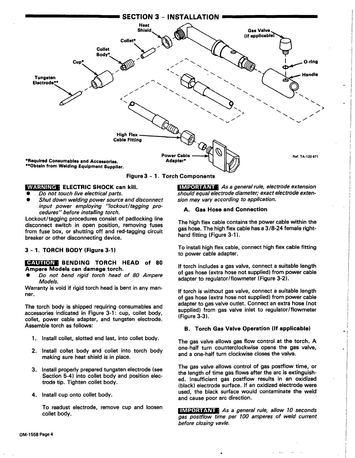
SECTION
3
-
INSTALLATION
I~YI1~II~c~
ELECTRIC
SHOCK
can
kill.
Do
not
touch
live
electrical
parts.
Shut
down
welding
power
source
and
disconnect
input
power
employing
lockout/tagging
pro
cedures
before
installing
torch.
Lockout/tagging
procedures
consist
of
padlocking
line
disconnect switch
in
open
position,
removing
fuses
from
fuse
box,
or
shutting
off
and
red-tagging
circuit
breaker
or
other
disconnecting
device.
3
-
1.
TORCH
BODY
(Figure
3-1)
CAUTION
________
BENDING
TORCH
HEAD
of
80
Ampere
Models
can
damage
torch.
Do
not
bend
rigid
torch
head
of
80
Ampere
Models.
Warranty
is
void
if
rigid
torch
head
is
bent
in
any
man
ner.
The
torch
body
is
shipped
requiring
consumables and
accessories
indicated
in
Figure
3-1:
cup,
collet
body,
collet,
power
cable
adapter,
and
tungsten
electrode.
Assemble
torch
as
follows:
1.
Install
collet,
slotted
end
last,
into
collet
body.
2.
Install
collet
body
and
collet
into
torch
body
making
sure
heat
shield
is
in
place.
3.
Install
properly
prepared
tungsten
electrode
(see
Section
5-4)
into
collet
body
and
position
elec
trode
tip.
Tighten
collet
body.
4.
Install
cup
onto
collet
body.
To
readust
electrode,
remove
cup
and
loosen
collet
body.
II ~i
psi
.
i.~
~I
~
As
a
general
rule,
electrode
extension
should
equal
electrode
diameter;
exact
electrode
exten
sion
may
vary
according
to
application.
A.
Gas
Hose
and
Connection
The
high
flex
cable
contains
the
power
cable
within
the
gas
hose.
The
high
flex
cable
has
a
3/8-24
female
right-
hand
fitting
(Figure
3-1).
To
install
high
flex
cable,
connect
high
flex
cable
fitting
to
power
cable
adapter.
If
torch
includes
a
gas
valve,
connect
a
suitable
length
of
gas
hose
(extra
hose
not
supplied)
from
power
cable
adapter
to
regulator/flowmeter
(Figure
3-2).
If
torch
is
without
gas
valve,
connect
a
suitable
length
of
gas
hose
(extra
hose
not
supplied)
from
power
cable
adapter
to
gas
valve
outlet.
Connect
an
extra
hose
(not
supplied)
from
gas
valve
inlet
to
regulator/flowmeter
(Figure
3-3).
B.
Torch
Gas
Valve
Operation
(If
applicable)
The
gas
valve
allows
gas
flow
control
at
the
torch.
A
one-half
turn
counterclockwise
opens
the
gas
valve,
and
a
one-half
turn
clockwise
closes
the
valve.
The
gas
valve
allows
control
of
gas
postflow
time,
or
the
length
of
time
gas
flows
after
the
arc
is
extinguish
ed.
Insufficient
gas
postflow
results
in
an
oxidized
(black)
electrode
surface.
If
an
oxidized
electrode
were
used,
the
black
surface
would
contaminate
the
weld
and
cause
poor
arc
direction.
IMPORTANT
As
a
general
rule,
allow 10
seconds
gas
postflow
time
per
100
amperes
of
weld
current
before
closing
vav/e.
Collet
Body
Gas
Tungsten
EloctrodeZZ.~~~
Requlred
Consumables
and
Accessories.
ceobtain
from
Welding
Equipment
Supplier.
Handle
>
Power
Cable
Adapter
Figure
3
-
1.
Torch
Components
Ref.
TA-120
671
OM-1
558
Page
4

Torch
Flowmeter
Figure
3
-
2.
GTAW
Torch
Connection
Diagram
For
Models
With
Gas
Valve
Torch
Figure
3
-
3.
GTAW
Torch
Connection
Diagrams
For
Models
Without
Gas
Valve
Ref.
TA-120
909
Ref.
TA-120
909
3
-
3.
POWER
CABLE
CONNECTION
(Figures
3-2
and
3-3)
WARNING
__________
ELECTRIC
SHOCK
can
kill.
Do
not
touch
live
electrical
parts.
Shut
down
welding
power
source
and
disconnect
input
power
employing
lockout/tagging
pro
cedures
before
installing
torch.
Lockout/tagging
procedures
consist
of
padlocking
line
disconnect
switch
in
open
position,
removing
fuses
from
fuse
box,
or
shutting
off
and
red-tagging
circuit
breaker
or
other
disconnecting
device.
The
high
flex
cable
assembly
contains
the
power
cable
within
the
gas
hose.
The
high
flex
cable
has
a
3/8-24
female
right-hand
fitting
(Figure
3-1).
To
install
high
flex
cable,
connect
high
flex
cable
fitting
to
power
cable
adapter
(see
Section
3-2A).
Connect
power
cable
adapter
to
weld
output
terminal
(Figures
3-2
and
3-3).
Valve
Work
Clamp
Gas
Cylinder
Work
Clamp
Gas
Cylinder
OM.1558
Page
5

WARNING
_________
ELECTRIC
SHOCK
can
kill.
Do
not
touch
five
electrical
parts.
Keep
all
covers
and
handle
in
place
while
operating.
ARC
RAYS,
SPARKS,
AND
HOT
SURFACES
can
burn
eyes
and
skin;
NOISE
can
damage
hearing.
Wear
correct
eye,
ear,
and
body
protection.
FUMES
AND
GASES
can
seriously
harm
your
health.
Ventilate
to
keep
from
breathing
fumes
and
gases.
If
ventilation
is
inadequate,
use
approved
breathing
apparatus.
HOT
METAL,
SPATTER,
AND
SLAG
can
cause
fire
and
burns.
.
.
SECTION
4
-
SEQUENCE
OF
OPERATION
3.
With
regulator/flowmeter
valve
closed,
open
gas
cylinder
valve.
4.
Set
power
source
for
desired
welding
amperage.
5.
Wear
dry
insulating
clothing
and
gloves
and
welding
helmet
with
proper
filter
lens
according
to
ANSI
Z49.1.
6.
Energize
welding
power
source.
7.
Set
gas
flow
to
desired
level
(requires
open
gas
valve).
I
I~
I
~i
.
V-i~I
~
Purge
gas
hose
to
clear
hose
of
air,
moisture,
or
any
other
contaminants.
Allow
gas
to
flow
2
to
3
minutes
on
new
torch;
5
to
6
seconds
thereafter.
8.
Begin
welding.
4
-2.
SHUTTING
DOWN
1.
Stop
welding.
~
As
a
genera/rule,
allow
10
seconds
of
gas
postf/ow
time
per
100
amperes
of
weld
current
before
closing
valve.
2.
Turn
off
welding
power
source.
3.
Turn
off
the
shielding
gas.
L~~U~E
HIGH
CONCENTRATION
OF
SHIELDING
GAS
can
harm
health
or
kill.
Shut
off
gas
supply
when
not
in
use.
-
SECTION
5
-
MAINTENANCE
Shut
down
welding
power
source
before
working
on
torch.
Disconnect
torch
from
we/ding
power
source
before
inspecting,
maintaining,
or
servicing.
Allow
a
cooling
period
before
servicing.
Once
a
week
Inspect
condition
of
torch
body
com
ponents.
Replace
cup,
heat
shield,
backcap,
and
0-rings
if
crack
ed.
Maintain
tight
fit
of
torch
components
to
ensure
good
weld
quality.
5
-3.
INSPECTING
HOSES,
CONNECTIONS
AND
CABLES
I!iTh~a~Il~Ief
ELECTRIC
SHOCK
can
kill.
Do
not
touch
live
electrical
parts.
Shut
down
welding
power
source
and
disconnect
input
power
employing
lockout/tagging
pro
cedures
before
inspecting,
maintaining,
or
ser
vicing.
Lockout/tagging
procedures
consist
of
padlocking
line
disconnect
switch
in
open
position,
removing
fuses
from
fuse
box,
or
shutting
off
and
red-tagging
circuit
breaker
or
other
disconnecting
device.
Watch
for
fire.
Have
a
fire
ext/n
quisher
nearby,
and
know
how
to
use.
Allow
work
and
equipment
to
cool
before
handl
ing.
MAGNETIC
FIELDS
FROM
HIGH
CURRENTS
can
affect
pacemaker
operation.
Wearers
should
consult
with
their
doctor
before
going
near
arc
welding,
gouging,
or
spot
welding
operations.
See
Section
1
-
Safety
Rules
for
additional
safety
infor
mation.
4
-
1.
GAS
TUNGSTEN
ARC
WELDING
(GTAW)
1.
Install
and
connect
torch
according
to
Section
3.
2.
Make
sure
backcap
and
all
gas
connections
are
securely
tightened.
5
-
1.
INSPECTION
AND
UPKEEP
-
Usage
and
shop
conditions
will
determine
frequency
and
type
of
maintenance
required.
Perform
inspections
once
a
week.
ITIJ:h~II~e~
ELECTRIC
SHOCK
can
kill;
HOT
SURFACES
can
cause
severe
burns.
Do
not
touch
five
electrical
parts.
Shut
down
welding
power
source
before
working
on
torch.
Disconnect
torch
from
welding
power
source
before
inspecting,
maintaining,
or
servicing.
Allow
a
cooling
period
before
servicing.
1.
Inspect
torch
for
broken
areas,
cracks
and
loose
parts;
tighten,
repair
and
replace
as
required.
2.
Remove
greaseand
dirtfrom
components,
and
moisture
from
electrical
parts
and
cables.
5
-2.
TORCH
BODY
MAINTENANCE
(Figure
3-1)
IaTLtlilI~e~
ELECTRIC
SHOCK
can
kill;
HOT
SURFACES
can
cause
severe
burns.
Do
not
touch
live
electrical
parts.
OM-1
558
Page
6
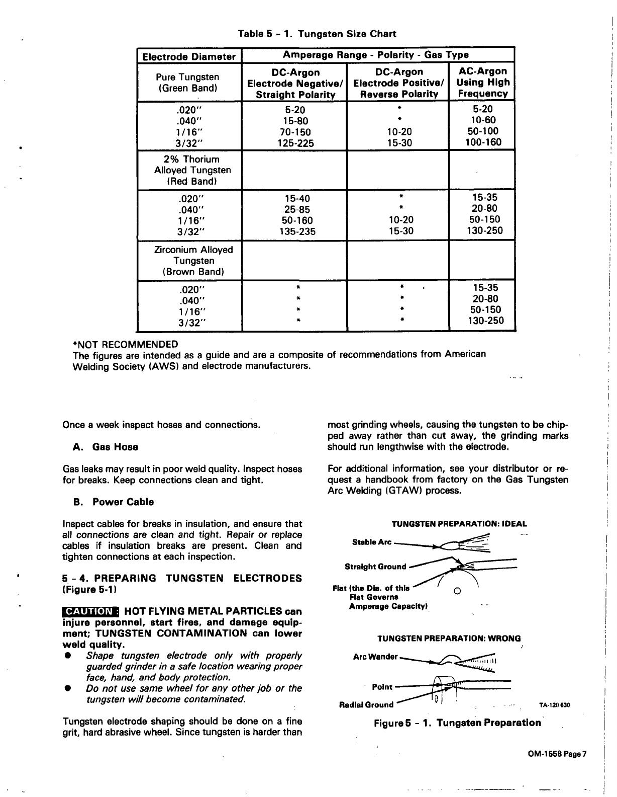
Table
5
-
1.
Tungsten
Size
Chart
*NOT
RECOMMENDED
The
figures
are
intended
as
a
guide
and
are
a
composite
of
recommendations
Welding
Society
(AWS)
and
electrode
manufacturers.
Once
a
week
inspect
hoses
and
connections.
A.
Gas
Hose
Gas
leaks
may
result
in
poor
weld
quality.
Inspect
hoses
for
breaks.
Keep
connections
clean
and
tight.
B.
Power
Cable
Inspect
cables
for
breaks
in
insulation,
and
ensure
that
all
connections
are
clean
and
tight.
Repair
or
replace
cables
if
insulation
breaks
are
present.
Clean
and
tighten
connections
at
each
inspection.
5
-
4.
PREPARING
TUNGSTEN
ELECTRODES
(Figure
5-1)
Tungsten
electrode
shaping
should
be
done
on
a
fine
grit,
hard
abrasive
wheel.
Since
tungsten
is
harder
than
most
grinding
wheels,
causing
the
tungsten
to
be
chip
ped
away
rather
than
cut
away,
the
grinding
marks
should
run
lengthwise
with
the
electrode.
For
additional
information,
see
your
distributor
or
re
quest
a
handbook
from
factory
on
the
Gas
Tungsten
Arc
Welding
(GTAW)
process.
Electrode
Diameter
Amperage
Range
-
Polarity
-
Gas
Type
Pure
Tungsten
(Green
Band)
~
DC-Argon
Electrode
Negative/
Straight
Polarity
DC-Argon
Electrode
Positive/
Reverse
Polarity
AC-Argon
Using
High
Frequency
.020
.040
1/16
3/32
5-20
15-80
70-150
125-225
*
10-20
15-30
5-20
10-60
50-100
100-160
2%
Thorium
Alloyed
Tungsten
(Red
Band)
.020
.040
1/16
3/32
15-40
25-85
50-160
135-235
*
*
10-20
15-30
15-35
20-80
50-150
130-250
Zirconium
Alloyed
Tungsten
(Brown
Band)
.020
.040
1/16
3/32
*
*
*
*
*
*
*
~
15-35
20-80
50-150
130-250
from
American
CAUTION
_________
HOT
FLYING
METAL
PARTICLES
can
injure
personnel,
start
fires,
and
damage
equip
ment;
TUNGSTEN
CONTAMINATION
can
lower
weld
quality.
Shape
tungsten
electrode
only
with
properly
guarded
grinder
in
a
safe
location
wearing
proper
face,
hand,
and
body
protection.
Do
not
use
same
wheel
for
any
other
job
or
the
tungsten
will
become
contaminated.
TUNGSTEN
PREPARATION:
IDEAL
--
Straight
Ground
Flat
(the
DIa.
of
this
Flat
Governs
Amperage
CapacIty)
TUNGSTEN
PREPARATION:
WRONG
Arc
Wander
~
Point
~
TA-120
630
RadIal
Ground
Figure
5
-
1.
Tungsten
PreparatIon
OM-1558Page7
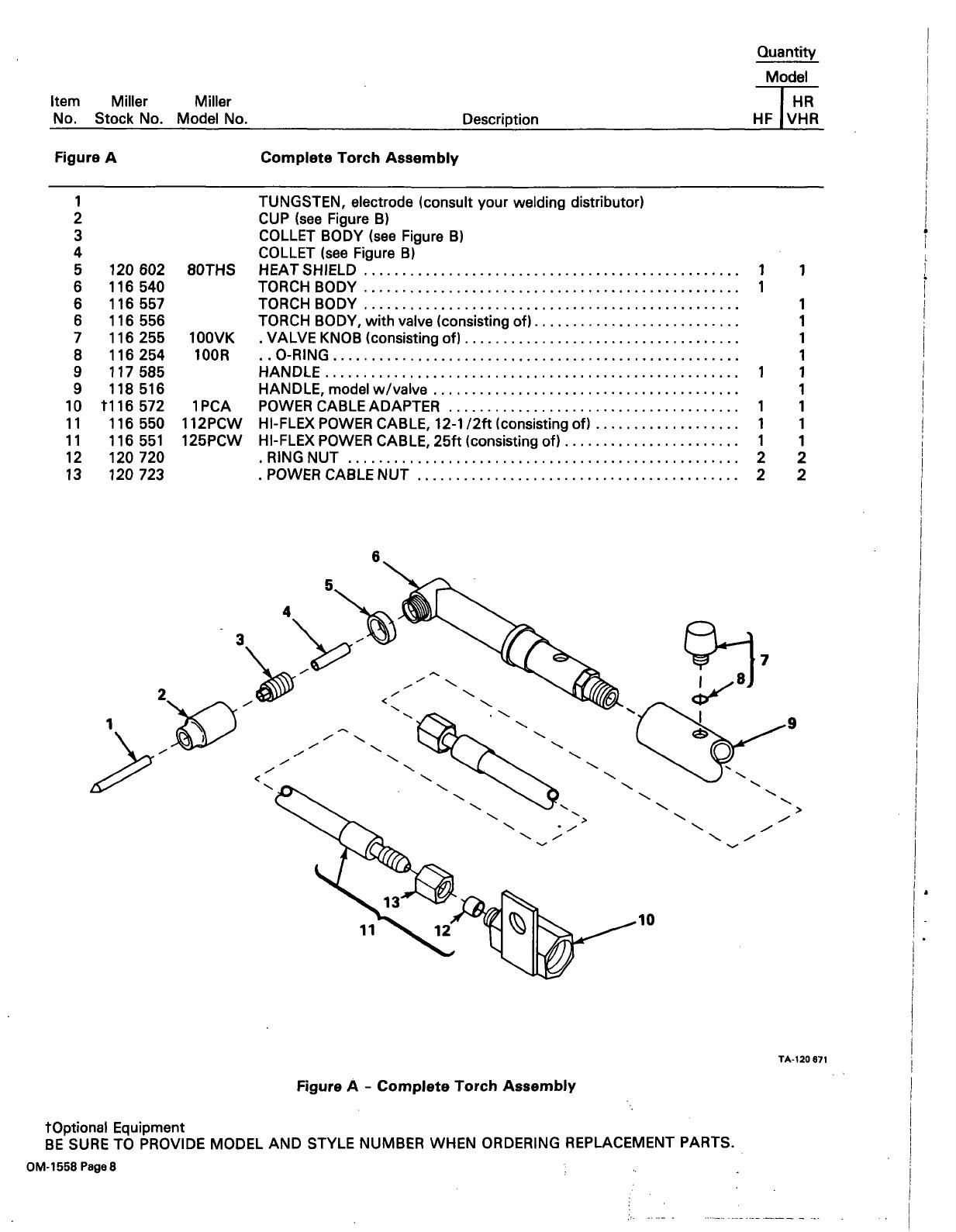
Quantity
Model
HR
Description
HF
VHR
tOptional
Equipment
BE
SURE TO
PROVIDE
MODEL
AND
STYLE
NUMBER
WHEN
ORDERING
REPLACEMENT
PARTS.
OM-1558Page8
Item
Miller
Miller
No.
Stock
No.
Model
No.
Figure
A
Complete
Torch
Assembly
1
2
3
4
5
120
602
8OTHS
TUNGSTEN,
electrode
(consult
your
welding
distributor)
CUP
(see
Figure
B)
COLLET
BODY
(see
Figure
B)
COLLET
(see
Figure
B)
HEAT
SHIELD
1
1
6
116
540
TORCHBODY
1
6
116
557
TORCHBODY
1
6
7
8
116
116
116
556
255
254
100VK
100R
TORCH
BODY,
with
valve
(consisting
of)
.
VALVE
KNOB
(consisting
of)
.
.0-RING
1
1
1
9
117
585
HANDLE
1
1
9
10
118
t116
516
572
1PCA
HANDLE,
model
w/valve
POWER
CABLE
ADAPTER
1
1
1
11
11
12
116
116
120
550
551
720
112PCW
125PCW
HI-FLEXPOWER
CABLE,
12-1
/2ft
(consisting
of)
HI-FLEX
POWER
CABLE,
25ft
(consisting
of)
.RINGNUT
1
1
2
1
1
2
13
120
723
.
POWER
CABLE
NUT
2 2
6.
4
3
2
7
.9
~.
11
10
I
>
TA-120
671
Figure
A
-
Complete
Torch
Assembly
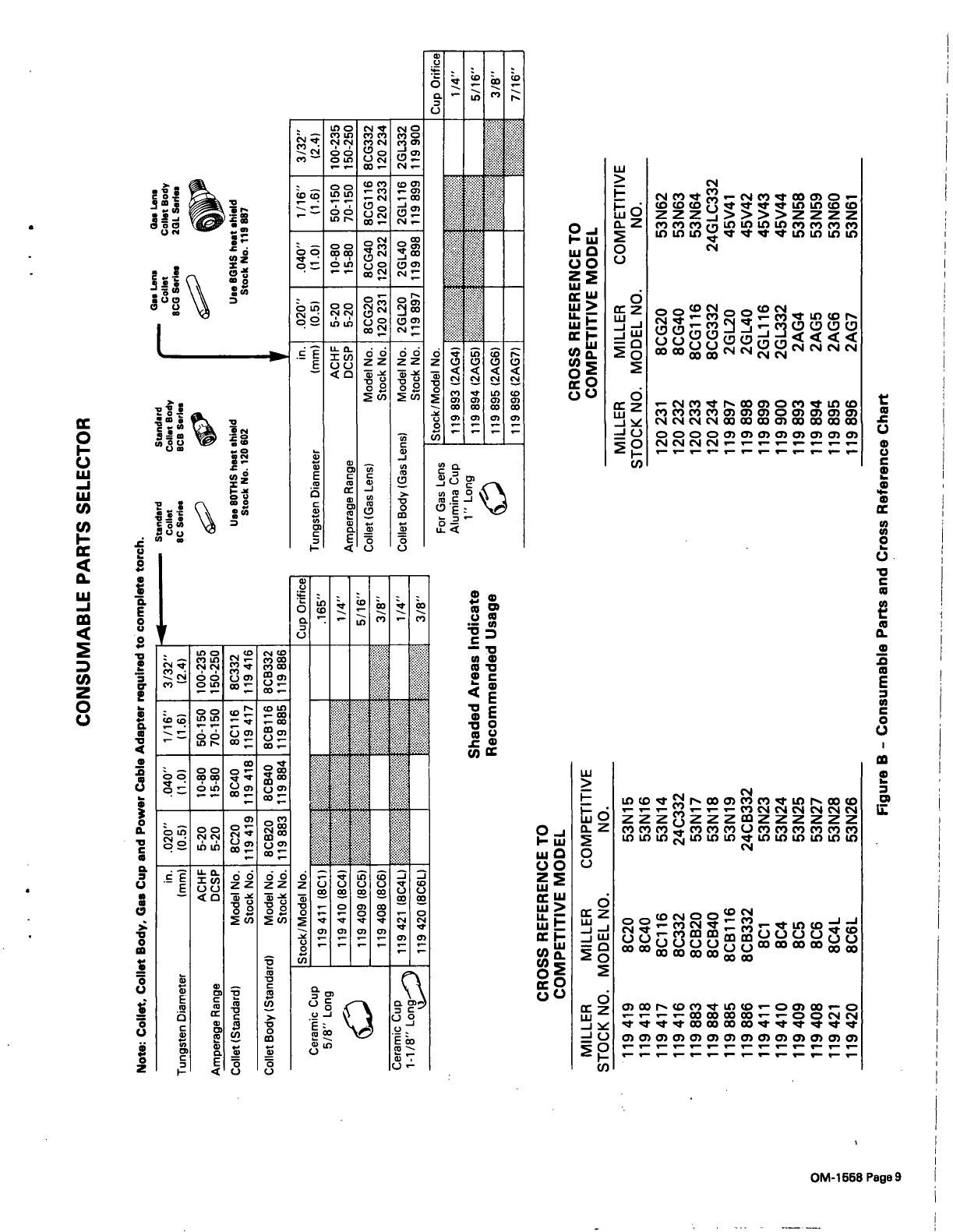
CONSUMABLE
PARTS
SELECTOR
CROSS
REFERENCE
TO
COMPETITIVE
MODEL
Shaded
Areas
Indicate
Recommended
Usage
Ga.
Len,
Ga.
Len.
C0II.t
Collet
Body
8CG
Sari..
2GL
Sepia,
U..
8GHS
heat
shield
Stock
No.
119
887
CROSS
REFERENCE
TO
COMPETITIVE
MODEL
Note:
Collet.
Coliet
Body.
Gee
Cup
and
Power
Cable
Adapter
required
to
complete
torch.
in
Tungsten
Diameter
(mm)
.020
(0.5)
.040
(1.0)
1/16
(1.6)
3/32
(2.4)
ACHF
Amperage
Range
DCSP
5-20
5-20
10-80
15-80
50-150
70-150
100-235
150-250
ColIet(Standard)
ModelNo.
StockNo.
8C20
119419
8C40
119418
8C116
119417
8C332
119416
Collet
Body
(Standard)
Standard
Collet
8C
Series
ModelNo.
8CB20
8CB40
8CB116
8CB332
Stock
No.
119883
119884
119885
119886
Standard
Collet
Body
BCB
Sari..
Us.
80THS
heat
shield
Stock
No.
120
602
Ceramic
Cup
5/8
Long
~
Stock/Model
No.
Cup
Orifice
119410(8C4)
1/4
119
409
(8C5)
5/16
119
408
(8C6)
3/8
Ceramic
Cup
~
1
1/8
Long
)
119
421
(8C4L)
~
1/4
119
420
(8C6L)
3/8
Tungsten
Diameter
in
(mm)
ACHF
.020
(0.5)
5-20
.040
(1.0)
10-80
1/16
(1.6)
50-150
3/32
(2.4)
100-235
AmperageRange
DCSP
5-20
15-80
70-150
150-250
Collet
(Gas
Lens)
Model
No.
Stock
No.
8CG20
120
231
8CG40
120
232
8CG1
16
120
233
8CG332
120
234
Collet
Body
(Gas
Lens)
Model
No.
2GL20
2GL40
2GL1
16
2GL332
Stock
No.
119897
119898
119899
119900
For
Gas
Lens
Alumina
Cup
1
Long
~
L5to~1M0de1
No.
Cup
Orifice
119
893
(2AG4)
1/4
Li~
894
)2AG5)
5/16
119895(2AG6)
3/8
119896(2AG7)
7/16
MILLER
STOCK
NO.
MILLER
MODEL
NO.
COMPETITIVE
NO.
119419
8C20
53N15
119418
8C40
53N16
119417
8C116
53N14
119416
8C332
24C332
119883
8CB20
53N17
119884
8CB40
53N18
119885
8CB116
53N19
119886
8CB332
24CB332
119411
8C1
53N23
119410
8C4
53N24
119409
8C5
53N25
119408
8C6
53N27
119421
8C4L
53N28
119420
8C6L
53N26
0
01
01
-~
CD
MILLER
STOCK
NO.
MILLER
MODEL
NO.
COMPETITIVE
NO.
120231
8CG20
53N62
120
232
8CG40
53N63
120233
8CG116
53N64
120
234
8CG332
24GLC332
119897
2GL20
45V41
119
898
2GL40
45V42
119899
2GL116
45V43
119900
2GL332
45V44
119893
2AG4
53N58
119894
2AG5
53N59
119895
2AG6
53N60
119896
2AG7
53N61
Figure
B
-
Consumable
Parts
and
Cross
Reference
Chart

/