American Hearth Madison Premium Fireplace (DVP42FP & DVP48FP) Owner's manual
- Category
- Fireplaces
- Type
- Owner's manual
This manual is also suitable for

Page 1
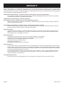
WARNING
FIRE OR EXPLOSION HAZARD
Failure to follow safety warnings exactly
could result in serious injury, death or
property damage.
— Do not store or use gasoline or other
ammable vapors and liquids in the
vicinity of this or any other appliance.
— WHAT TO DO IF YOU SMELL GAS
• Do not try to light any appliance.
• Do not touch any electrical switch; do
not use any phone in your building.
• Leave the building immediately.
• Immediately call your gas supplier
from a neighbor’s phone. Follow the
gas supplier’s instructions.
• If you cannot reach your gas supplier,
call the re department.
—
Installation and service must be performed
by a qualied installer, service agency or
the gas supplier.
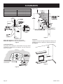
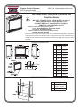
NOTE: Barrier required, but may be sold separately.
HOT GLASS
DO NOT TOUCH
NEVER
WILL
CAUSE BURNS.
GLASS
UNTIL COOLED.
ALLOW CHILDREN
TO TOUCH GLASS.
WARNING
A barrier designed to reduce the risk of burns from the
hot viewing glass is provided with this appliance and shall
be installed for the protection of children and other at-risk
individuals.
INSTALLATION INSTRUCTIONS
AND OWNER’S MANUAL
INSTALLER:
Leave this manual with the appliance.
CONSUMER:
Retain this manual for future reference.
This appliance may be installed in an aftermarket,
permanently located, manufactured home (USA
only) or mobile home, where not prohibited by
state or local codes.
This appliance is only for use with the type of gas
indicated on the rating plate. This appliance is
not convertible for use with other gases, unless
a certied kit is used.
WARNING
If not installed, operated and maintained in
accordance with the manufacturer’s instruc-
tions, this product could expose you to sub-
stances in fuel or from fuel combustion which
can cause death or serious illness.
DIRECT VENT
ZERO CLEARANCE
GAS FIREPLACE HEATER
MILLIVOLT STANDING PILOT
DVP(42,48)FP3(0,1,2,3)(N,P)-4
INTERMITTENT PILOT
DVP(42,48)FP7(0,1,2,3)(N,P)-5
REMOTE RF
DVP(42,48)FP9(1,3)(N,P)-6
GAS-FIRED
UL FILE NO.
MH30033

39359-0-1018Page 2
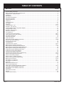
TABLE OF CONTENTS
Important Safety Information......................................................................................................................................................... 3
Safety Information For Users Of Propane Gas ............................................................................................................................. 4
Requirements For Massachusetts ................................................................................................................................................ 5
Introduction ................................................................................................................................................................................... 6
Specications ................................................................................................................................................................................ 7
Vent System Identication............................................................................................................................................................. 8
Special Vent Systems ................................................................................................................................................................... 9
Fireplace Dimensions ................................................................................................................................................................... 9
Clearances .................................................................................................................................................................................. 10
Locating Fireplace........................................................................................................................................................................11
Gas Supply ................................................................................................................................................................................. 12
Installation .............................................................................................................................................................................. 13-16
Venting Fireplace - Top .......................................................................................................................................................... 17-19
Examples - Top Vent Run ........................................................................................................................................................... 20
Venting Examples When Using DVA47 Adaptor ......................................................................................................................... 21
Venting Fireplace - Rear ............................................................................................................................................................. 22
Examples - Rear Vent Run ......................................................................................................................................................... 23
Rear Vent Conversion ................................................................................................................................................................. 24
Vent Clearances.......................................................................................................................................................................... 25
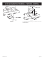
8” Venting Framing And Finishing .......................................................................................................................................... 26-27
6-5/8" Venting Framing And Finishing .................................................................................................................................... 28-29
Termination Clearances .............................................................................................................................................................. 30
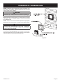
Horizontal Termination ................................................................................................................................................................ 31
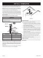
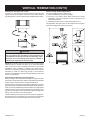
Vertical Termination ................................................................................................................................................................ 32-33
DVVK-4RE Vent Kit Installation Instructions .......................................................................................................................... 34-36
DVVK-5F Flex Vent Instructions ................................................................................................................................................. 37
Propane Gas Conversion............................................................................................................................................................ 38
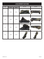
Log Identication ......................................................................................................................................................................... 39
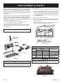
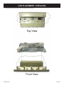
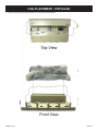
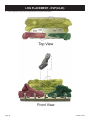
Log Placement (4 Log Set) .................................................................................................................................................... 40-45
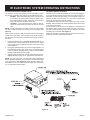
Millivolt System Operating Instructions .................................................................................................................................. 46-47
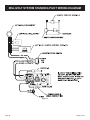
Millivolt System Standing Pilot Wiring Diagram .......................................................................................................................... 48
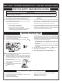
Millivolt System Standing Pilot Lighting Instructions ................................................................................................................... 49
Millivolt System Standing Pilot Troubleshooting ......................................................................................................................... 50
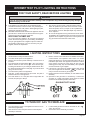
IPI Electronic System Operating Instructions.............................................................................................................................. 51
IPI Electronic System Wiring Diagram ........................................................................................................................................ 52
Intermittent Pilot Lighting Instructions ......................................................................................................................................... 53
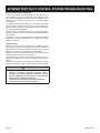
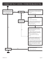
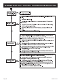
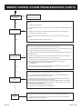
Intermittent Pilot Control System Troubleshooting ................................................................................................................. 54-56
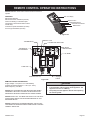
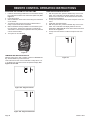
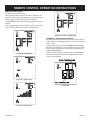
Remote Control Operation Instructions.................................................................................................................................. 57-62
Remote Control Wiring Diagram ................................................................................................................................................. 63
Remote Control - Lighting Instructions........................................................................................................................................ 64
Remote Control System Troubleshooting .............................................................................................................................. 65-66
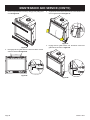
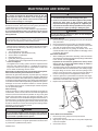
Maintenance And Service ...................................................................................................................................................... 67-69
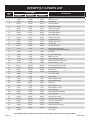
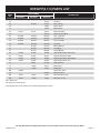
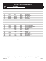
DVP42FP(3,5,7,9) Parts List.................................................................................................................................................. 70-71
DVP48FP(3,5,7,9) Parts List.................................................................................................................................................. 72-73
Parts View ................................................................................................................................................................................... 74
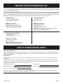
Master Parts Distributor List........................................................................................................................................................ 75
How To Order Repair Parts ......................................................................................................................................................... 75
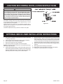
FBB4 Optional Variable Speed Blower Installation ................................................................................................................ 76-77
Junction Box Wiring Installation Instructions............................................................................................................................... 78
Optional Brick Liner Installation Instructions ............................................................................................................................... 78
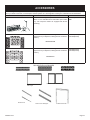
Accessories................................................................................................................................................................................. 79
Quick Reference Guide.......................................................................................................................................................... 80-81
Warranty ..................................................................................................................................................................................... 82
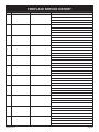
Fireplace Service History ............................................................................................................................................................ 83
SECTION PAGE

39359-0-1018 Page 3
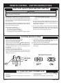
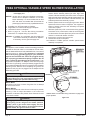
DO NOT OPERATE THIS APPLIANCE WITHOUT GLASS FRONT PANEL INSTALLED
Before enclosing the vent pipe assembly, operate the appliance to ensure it is venting properly.
• If this appliance is installed directly on carpeting, tile or
other combustible material other than wood ooring the
appliance shall be installed on a metal or wood panel
extending the full width and depth of the appliance.
The base referred to above does not mean the reproof
base as used on wood stoves. The protection is for rugs
that are extremely thick and light colored tile.
• Children and adults should be alerted to the hazards of
high surface temperatures and should stay away to avoid
burns or clothing ignition.
• Young children should be carefully supervised when they
are in the same room as the appliance.
• Clothing or other ammable material should not be placed
on or near the appliance.
• Adequate accessibility clearances for servicing and proper
operation.
• This appliance must not share or be connected to a ue
serving a separate solid-fuel burning appliance.
• Keep the area around your appliance clear of combustible
materials, gasoline and other ammable vapor and liquids.
• Under no circumstances should any solid fuels (wood,
coal, paper or cardboard etc.) be used in this appliance.
• The ow of combustion and ventilation air must not be
obstructed in any way.
• Young children should be carefully supervised when
they are in the same room as the appliance. Toddlers,
young children, and others may be susceptible to ac-
cidental contact burns. A physical barrier is recom-
mended if there are at-risk individuals in the house. To
restrict access to a replace or stove, install an adjust-
able safety gate to keep toddlers young children, and
other at-risk individuals out of the room and away from
hot surfaces.
• A barrier designed to reduce the risk of burns from the
hot viewing glass is provided with this appliance and
shall be installed for the protection of children and other
at-risk individuals. Barrier required, may be sold sepa-
rately.
• If the barrier becomes damaged, the barrier shall be
replaced with the manufacturer’s barrier for this appli-
ance.
• Any safety screen, guard, or barrier removed for servic-
ing an appliance must be replaced prior to operating the
appliance.
• Due to high temperatures the appliance should be located
out of trafc and away from furniture and draperies.
• The glass front or any part removed for servicing the
appliance must be replaced prior to operating the
appliance. Work should be done by a qualied service
person.
• Keep burner and control compartment clean.
• Vent cap is hot while replace is in operation.
• Installation and repair should be done by a qualied
service person. The appliance should be inspected
before use and at least annually by a qualied service
person. More frequent cleaning may be required due
to excessive lint from carpeting, bedding materials, etc.
It is imperative that control compartments, burners and
circulating air passageways of the appliance be kept
clean.
• Do not put anything around the replace that will obstruct
the ow of ventilation air.
• Clearance in accordance with local installation codes
and the requirements of the gas supplier.
• Do keep the appliance area clear and free from
combustible material, gasoline and other ammable
vapors and liquids.
• Do examine venting system periodically and replace
damaged parts.
• Do make a periodic visual check of pilot and burners.
Clean and replace damaged parts.
• CAUTION: The glass used in your replace is
tempered glass. If the glass is cracked or damaged in
any way, it should be replaced only with a complete
glass frame assembly from Empire. See parts list on
Pages 69 to 73 for ordering.
• Do not use this replace if any part has been under
water. Immediately call a qualied service technician to
inspect the heater and to replace any part of the control
system and any gas control which has been under water.
• Any safety screen or guard removed for servicing
an appliance must be replaced prior to operating the
appliance.
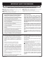
IMPORTANT SAFETY INFORMATION
DANGER: Indicates a hazardous situation which, if not avoid-
ed, will result in death or serious injury.
WARNING: Indicates a hazardous situation which, if not
avoided, could result in death or serious injury.
CAUTION: Indicates a hazardous situation which, if not avoid-
ed, could result in minor or moderate injury.
NOTICE: Addresses practices not related to personal injury.

39359-0-1018Page 4
Some people cannot smell well. Some people cannot smell the
odor of the chemical put into the gas. You must nd out if you
can smell the odorant in propane. Smoking can decrease your
ability to smell. Being around an odor for a time can affect your
sensitivity or ability to detect that odor. Sometimes other odors in
the area mask the gas odor. People may not smell the gas odor
or their minds are on something else. Thinking about smelling a
gas odor can make it easier to smell.
The odorant in Propane Gas is colorless, and it can fade under
some circumstances. For example, if there is an underground
leak, the movement of the gas through soil can lter the odorant.
Odorants in Propane Gas also are subject to oxidation. This fading
can occur if there is rust inside the storage tank or in iron gas pipes.
The odorant in escaped gas can adsorb or absorb onto or into
walls, masonry and other materials and fabrics in a room. That will
take some of the odorant out of the gas, reducing its odor intensity.
Propane Gas may stratify in a closed area, and the odor intensity
could vary at different levels. Since it is heavier than air, there may
be more odor at lower levels. Always be sensitive to the slightest
gas odor. If you detect any odor, treat it as a serious leak. Imme-
diately go into action as instructed earlier.
Propane is a ammable gas which can cause res and explo-
sions. In its natural state, propane is odorless and colorless.
You may not know all the following safety precautions which
can protect both you and your family from an accident. Read
them carefully now, then review them point by point with the
members of your household. Someday when there may not
be a minute to lose, everyone’s safety will depend on knowing
exactly what to do. If, after reading the following information,
you feel you still need more information, please contact your
gas supplier.
• Learn to recognize the odor of Propane Gas. Your local Propane
Gas Dealer can give you a “Scratch and Sniff” pamphlet. Use
it to nd out what the propane odor smells like. If you suspect
that your Propane Gas has a weak or abnormal odor, call your
Propane Gas Dealer.
• If you are not qualied, do not light pilot lights, perform service,
or make adjustments to appliances on the Propane Gas system.
If you are qualied, consciously think about the odor of Propane
Gas prior to and while lighting pilot lights or performing service
or making adjustments.
• Sometimes a basement or a closed-up house has a musty
smell that can cover up the Propane Gas odor. Do not try to
light pilot lights, perform service, or make adjustments in an
area where the conditions are such that you may not detect
the odor if there has been a leak of Propane Gas.
• Odor fade, due to oxidation by rust or adsorption on walls of
new cylinders and tanks, is possible. Therefore, people should
be particularly alert and careful when new tanks or cylinders
are placed in service. Odor fade can occur in new tanks, or
reinstalled old tanks, if they are lled and allowed to set too
long before relling. Cylinders and tanks which have been out
of service for a time may develop internal rust which will cause
odor fade. If such conditions are suspected to exist, a periodic
sniff test of the gas is advisable. If you have any question
about the gas odor, call your Propane Gas Dealer. A peri-
odic sniff test of the Propane Gas is a good safety measure
under any condition.
• If, at any time, you do not smell the Propane Gas odorant and
you think you should, assume you have a leak. Then take the
same immediate action recommended above for the occasion
when you do detect the odorized Propane Gas.
• If you experience a complete “gas out,” (the container is under
no vapor pressure), turn the tank valve off immediately. If the
container valve is left on, the container may draw in some air
through openings such as pilot light orices. If this occurs, some
new internal rusting could occur. If the valve is left open, then
treat the container as a new tank. Always be sure your con-
tainer is under vapor pressure by turning it off at the container
before it goes completely empty or having it relled before it is
completely empty.
• Do not operate electric switches, light matches, use your phone.
Do not do anything that could ignite the gas.
• Get everyone out of the building, vehicle, trailer, or area. Do
that IMMEDIATELY.
• Close all gas tank or cylinder supply valves.
• Propane Gas is heavier than air and may settle in low areas
such as basements. When you have reason to suspect a gas
leak, keep out of basements and other low areas. Stay out until
reghters declare them to be safe.
• Use your neighbor’s phone and call a trained Propane Gas
service person and the re department. Even though you may
not continue to smell gas, do not turn on the gas again. Do not
re-enter the building, vehicle, trailer, or area.
• Finally, let the service man and reghters check for escaped
gas. Have them air out the area before you return. Properly
trained Propane Gas service people should repair the leak,
then check and relight the gas appliance for you.
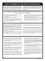
SOME POINTS TO REMEMBER
NO ODOR DETECTED - ODOR FADE
PROPANE GAS WARNING ODOR
If a gas leak happens, you should be able to smell the gas because of the odorant put in the Propane Gas.
That’s your signal to go into immediate action!
SAFETY INFORMATION FOR USERS OF PROPANE GAS

39359-0-1018 Page 5
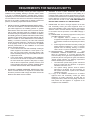
REQUIREMENTS FOR MASSACHUSETTS
For all side wall horizontally vented gas fueled equipment
installed in every dwelling, building or structure used in whole
or in part for residential purposes, including those owned or
operated by the Commonwealth and where the side wall exhaust
vent termination is less than seven feet above nished grade in
the area of the venting, including but not limited to decks and
porches, the following requirements shall be satised:
1. INSTALLATION OF CARBON MONOXIDE DETECTORS.
At the time of installation of the side wall horizontal vented
gas fueled equipment, the installing plumber or gastter
shall observe that a hard wired carbon monoxide detector
with an alarm and battery back-up is installed on the oor
level where the gas equipment is to be installed. In addition,
the installing plumber or gastter shall observe that a battery
operated or hard wired carbon monoxide detector with an
alarm is installed on each additional level of the dwelling,
building or structure served by the side wall horizontal
vented gas fueled equipment. It shall be the responsibility
of the property owner to secure the services of qualied
licensed professionals for the installation of hard wired
carbon monoxide detectors
a. In the event that the side wall horizontally vented gas
fueled equipment is installed in a crawl space or an
attic, the hard wired carbon monoxide detector with
alarm and battery back-up may be installed on the next
adjacent oor level.
b. In the event that the requirements of this subdivision
can not be met at the time of completion of installation,
the owner shall have a period of thirty days to comply
with the above requirements; provided, however, that
during said thirty day period, a battery operated carbon
monoxide detector with an alarm shall be installed.
2. APPROVED CARBON MONOXIDE DETECTORS. Each
carbon monoxide detector as required in accordance with
the above provisions shall comply with NFPA 720 and be
ANSI/UL 2034 listed and IAS certied.
3. SIGNAGE. A metal or plastic identication plate shall be
permanently mounted to the exterior of the building at a
minimum height of eight feet above grade directly in line with
the exhaust vent terminal for the horizontally vented gas fueled
heating appliance or equipment. The sign shall read, in print
size no less than 1/2 inch in size, “GAS VENT DIRECTLY
BELOW. KEEP CLEAR OF ALL OBSTRUCTIONS”.
4. INSPECTION. The state or local gas inspector of the side
wall horizontally vented gas fueled equipment shall not
approve the installation unless, upon inspection, the inspector
observes carbon monoxide detectors and signage installed
in accordance with the provisions of 248 CMR 5.08(2)(a) 1
through 4.
(b) EXEMPTIONS: The following equipment is exempt from
248 CMR 5.08(2)(a)1 through 4:
1. The equipment listed in Chapter 10 entitled
“Equipment Not Required To Be Vented” in the most
current edition of NFPA 54 as adopted by the Board;
and
2. Product Approved side wall horizontally vented gas
fueled equipment installed in a room or structure
separate from the dwelling, building or structure
used in whole or in part for residential purposes.
(d) MANUFACTURER REQUIREMENTS - GAS
EQUIPMENT VENTING SYSTEM NOT PROVIDED.
When the manufacturer of a Product Approved side
wall horizontally vented gas fueled equipment does not
provide the parts for venting the ue gases, but identies
“special venting systems”, the following requirements
shall be satised by the manufacturer:
1. The referenced “special venting system” instructions
shall be included with the appliance or equipment
installation instructions; and
2. The “special venting systems” shall be Product
Approved by the Board, and the instructions for
that system shall include a parts list and detailed
installation instruction.
(e) A copy of all installation instructions for all Product
Approved side wall horizontally vented gas fueled
equipment, all venting instructions, all parts lists for
venting instructions, and/or all venting design instructions
shall remain with the appliance or equipment at the
completion of the installation.

39359-0-1018Page 6
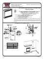
Instructions to Installer
1. Installer must leave instruction manual with owner after
installation.
2. Installer must have owner ll out and mail warranty card supplied
with the replace.
3. Installer should show owner how to start and operate the replace.
This direct vent gas replace heater is designed to operate with
all combustion air being siphoned from the outside of the building
and all exhaust gases expelled to the outside of the building. The
information contained in this manual pertains to all models and gas
control systems unless otherwise noted.
WARNING
This unit is not for use with solid fuels.
Appliance Certication
This replace is design certied in accordance with American
National Standard/CSA Standard ANSI Z21.88/CSA 2.33 and by
Underwriters Laboratories as a Direct Vent Gas Fireplace Heater
and shall be installed according to these instructions.
Consult your local building code agency, prior to installation, to ensure
compliance with local codes-including permits and inspections.
The replace, when installed, must be electrically grounded in
accordance with local codes or, in absence of local codes, with the
National Electric Code ANSI/NFPA 70 or Canadian Electric code,
CSA C22.1, if an external electrical source is utilized.
These models may be installed in a bedroom or bed-sitting room
in the U.S.A. and Canada.
Qualied Installing Agency
Installation and replacement of gas piping, gas utilization equipment
or accessories and repair and servicing of equipment shall be
performed only by a qualied agency. The term “qualied agency”
means any individual, rm, corporation or company which either in
person or through a representative is engaged in and is responsible for
(a) the installation or replacement of gas piping or (b) the connection,
installation, repair or servicing of equipment, who is experienced in
such work, familiar with all precautions required and has complied
with all the requirements of the authority having jurisdiction.
Commonwealth of Massachusetts: The installation must be
made by a licensed plumber or gas tter in the Commonwealth
of Massachusetts.
The installation must conform with local codes or, in the absence of
local codes, with the National Fuel Gas Code ANSI Z223.1/NFPA
54* Natural Gas and Propane Installation Code, or CSA B149.1 in
Canada. *Available from the American National Standards Institute,
Inc. 11 West 42nd St., New York, N.Y. 10036.
WARNING
ANY CHANGE TO THIS FIREPLACE OR ITS CONTROLS
CAN BE DANGEROUS.
Improper installation or use of the replace can cause
serious injury or death from re, burns, explosions, or
carbon monoxide poisoning.
Any alteration of the original design, installed other than as
shown in these instructions or use with a type of gas not
shown on the rating plate is the responsibility of the person
and company making the change.
Important
All correspondence should refer to complete Model Number, Serial
Number and type of gas.
High Altitude
When installing this unit at an elevation above 2000 feet (in the
United States) it may be necessary to decrease the input rating by
changing the existing burner orice to a smaller size. Generally,
input should be reduced 4 percent for each 1000 feet above sea
level. However, if the heating value of the gas has been reduced,
this general rule may not apply. Check with local gas utility for proper
orice size identication.
Canadian High Altitude
Altitude: 0-4500 feet (0-1370 m)
When installing this unit at an elevation above 4500 feet (in Canada),
check with local authorities.
Consult your local gas utility for assistance in determining the proper
orice for location.
Preparation
This direct vent gas replace and its components are tested and
safe when installed in accordance with this Installation Manual.
Report to your dealer any parts damaged in shipment, specically
check glass condition. Do not install unit with damaged, incomplete,
or substitute parts. Read all instructions before starting installation
and follow these instructions carefully during installation to insure
maximum benet and safety. Failure to follow them will void your
warranty and may present a re hazard.
The warranty will be voided by, and the warranter disclaims any
responsibility for the following actions:
• Installation of any damaged replace or vent system component.
• Modication of the replace or direct vent system.
• Installation other than as instructed by Empire Comfort Systems,
Inc.
• Improper positioning of the logs, glass door or decorative rock.
• Installation and/or use of any component part not manufactured
or approved by manufacturer.
INTRODUCTION

39359-0-1018 Page 7
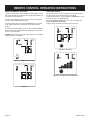
Remote Control Options And Accessories Description
FRBC Millivolt/IP Battery Remote ON/OFF
FRBTC Millivolt/IP Battery Remote T-Stat
TMW Millivolt/IP WIRELESS Wall Thermostat
TRW Millivolt/IP REED SWITCH Wall Thermostat
FWS-1 Millivolt/IP Wall Switch
FREC Electric Remote
FBB4 Blower Assembly
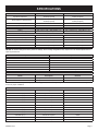
DVP42 DVP48
Input Btu/hr Maximum
28,000 (Natural)
28,000 (Propane)
30,000 (Natural)
30,000 (Propane)
Btu/hr Minimum (millivolt only)
19,000 (Natural)
22,000 (Propane)
20,500 (Natural)
24,000 (Propane)
KWH (Maximum) 8.2 8.8
(Minimum) 5.5 6.0
NATURAL
Orice #38 (.1015) P-203 - (DVP42FP(3,7,9)) #37 (.1040) P-213 - (DVP48FP(3,7,9))
Air Shutter Opening 1/8"(3.2mm) 1/8"(3.2mm)
PROPANE
Orice #52 (.0635") P-185 1.65MM P-250
Air Shutter Opening FULL OPEN FULL OPEN
Height without standoff 34 3/4"(883mm) 34 3/4"(883mm)
Width 43"(1092mm) 49"(1245mm)
Depth 19 7/8"(505mm) 19 7/8"(505mm)
Gas Inlet Shutoff Valve (Pipe) 1/2 NPT 1/2 NPT
NOTICE: Air shutter settings are factory minimum settings. Some venting congurations may require minor air shutter adjustments for
optimum performance.
SPECIFICATIONS
FIREPLACE BARRIER SCREENS
Model Description Used On
DVFB42TBL Fireplace Barrier Screen, Matte Black DVP42FP
DVFB48TBL Fireplace Barrier Screen, Matte Black DVP48FP
NOTICE: A rescreen is required for operation of the appliance, but are sold separately. Follow the instructions that come with your re-
screen for proper installation.
CONVERSION KITS
Models Description Part Numbers
DVP42FP3(0,1) Propane to Natural 18824
DVP42FP3(0,1) Natural to Propane 18821
DVP42FP7(0,1) Propane to Natural 32016
DVP42FP7(0,1) Natural to Propane 32021
DVP42FP91 Propane to Natural 35462
DVP42FP91 Natural to Propane 35463
DVP48FP3(0,1) Propane to Natural 18825
DVP48FP3(0,1) Natural to Propane 18822
DVP48FP7(0,1) Propane to Natural 32017
DVP48FP7(0,1) Natural to Propane 32022
DVP48FP91 Propane to Natural 35464
DVP48FP91 Natural to Propane 35445

39359-0-1018Page 8
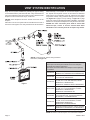
VENT SYSTEM IDENTIFICATION
Figure 1
Begin the vent system installation by selecting the type of venting
to be installed and the path that it will take. Verify that clearances
are met throughout the path of the venting system. Determine if the
replace is to be vented out the top or out the rear.
NOTICE: Some replaces cannot be vented out the rear of the
replace.
Determine how the vent system will be terminated out the side of
the house or through the roof. Verify clearances for the termination.
When selecting a vent system for use with the replace, refer to
the “Special Vent Systems” section in this manual to determine
what systems are acceptable. Check all clearances and venting
components. Identify if any problems existing in the vent system.
Use Figure 22 on page 17 for top venting, or Figure 35 on page
22 for rear venting to eliminate issues after installation. Check pipe
diameter on vent system and replace to verify the size is the same.
NOTICE: All outer connection joints must be sealed with
aluminum tape, screws or silicone sealant rated above
300°F/149°C. The inner ue joints do not require any sealant.
SPECIAL VENTING COMPONENTS (SIMPSON DURAVENT)
See Empire Comfort Systems Retail Price List for Simpson
Duravent part numbers and pricing.
Special DV Vent Kits Available from Empire Comfort Systems,
Inc. dealers.
DVVK-4VP
Direct-Vent Fireplace Vent Kit - Vertical, Includes
SD46DVA-VCH, SD46DVA-F6 and SD46DVA-SC
DVVK-4RE
Direct-Vent Fireplace Vent Kit, Thru-the-wall, for
5 to 13-3/4 inch wall thickness
DVVK-4TP
Direct-Vent Fireplace Vent Kit for Top Vent, Thru-
the-wall, 8 to 11 inch wall thickness, Includes
SD46DVA-HC, SD46DVA-E90,
SD46DVA-09, SD46DVA-08A and SD46DVAWT
DVVK-4TSP
Direct-Vent Fireplace Vent Kit for Top Vent, Thru-
the-wall, 5 to 7 inch wall thickness, Includes
SD46DVA-HC, SD46DVA-E90,
SD46DVA-06 and SD46DVA-WT
DVVK-5RP
Direct-Vent Fireplace Vent Kit for Rear Vent, 6 to
12 inch wall thickness, Includes SD-58DVA06,
SD-58DVAHC, and SD58DVAWTEC
DVVK-5TP
Direct-Vent Fireplace Vent Kit for Top Vent, Thru-
the-wall, 4 to 6 inch wall thickness, Includes
SD58DVAE90, SD58DVAHC,
SD58DVA06, and SD58DVAWTEC
DVVK-5VP
Direct Vent Fireplace Vent Kit - Vertical, Includes
SD58DVAVCH, SD58DVASC, and SD58DVAF6
DVVK-5F Horizontal Flex Vent Kit (4’ Flex) (1.22m)
NOTE: All DVVK-4 Vent Kits require use of the DVA47 adaptor.
*NOTE: If using three 90° elbows during horizontal
termination, see Figure 30.

39359-0-1018 Page 9
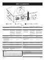
The following vent systems are acceptable for use with the
DVP (42,48) series replaces:
• Simpson Duravent® GS 5" - 8"
• American Metal Products 5" - 8"
• Selkirk Direct-Temp® 5" - 8"
• Security Secure Vent® 5" - 8"
• Excel DV Venting 5” - 8”
• BDM 5” - 8”
• MetalFab SureSeal® 5” - 8”
• Empire Flexvent Kit DVVK-5F
The following vent systems are acceptable for use with the
DVA-47 adaptor vertically off top of replace only:
• Simpson Duravent
®
GS 4" - 6⅝"
• American Metal Products 4" - 6⅝"
• Selkirk Direct-Temp® 4" - 6⅝"
• Security Secure Vent® 4" - 6⅝"
• Excel DV Venting 4” - 6⅝”
• BDM 4” - 6 5/8”
• MetalFab SureSeal® 4” - 6⅝”
• Empire Horizontal Round Termination Kits DVVK-4RE, DVVK-4REVS
NOTE: DVA-47 Not for use with Flex Vent Kits.
Figure 2
FIREPLACE DIMENSIONS
A B C D E F G H I J K
DVP42 43”
(1092mm)
40”
(1016mm)
25 1/16”
(636 mm)
37 5/8”
(956 mm)
34 3/4”
(883 mm)
19 7/8”
(505 mm)
26”
(660 mm)
7 1/8”
(181 mm)
26 1/2”
(826 mm)
13 1/4”
(337 mm)
12 3/4”
(324 mm)
DVP48 49”
(1245mm)
46”
(1168mm)
25 1/16”
(636 mm)
37 5/8”
(956 mm)
34 3/4”
(883 mm)
19 7/8”
(505 mm)
26”
(660 mm)
7 1/8”
(181 mm)
32 1/2”
(826 mm)
16 1/4”
(413 mm)
12 3/4”
(324 mm)
SPECIAL VENT SYSTEMS

39359-0-1018Page 10
CLEARANCES
Clearance to Combustibles
Back 0" (0 mm)
Side 0" (0 mm)
Floor 0" (0 mm)
Top Stand-off 0" (0 mm)
Top Framing Edge 3" (76 mm)
Note A: See Figure 5 for maximum mantel depth.
Note B: See Figure 5 for minimum height above unit.
Figure 3
Combustible Material
No greeting cards, stockings or ornamentation of any type should
be placed on or attached to the replace. The ow of heat can
ignite combustibles.
Figure 4
Mantel Chart
Figure 5
Clearances
Clearance from top front edge of replace to ceiling is 36”
Clearance from side of replace to adjacent sidewall is 6”.
See Figure 6.
(914mm)
Figure 6

39359-0-1018 Page 11
Figure 7
NOTICE: Island and Room Divider installation is possible as long
as the horizontal portion of the vent system does not exceed 20 feet
with a minimum vertical run of 8 feet. See details in Venting Section.
When you install your Direct Vent Fireplace in Room divider or Flat
on wall corner positions, a minimum of 6 inches clearance must
be maintained from the perpendicular wall and the front edge of
the appliance.
CABINET
INSTALLATION
FLUSH WALL
INSTALLATION
ROOM DIVIDER
INSTALLATION
CORNER
INSTALLATION
ANGLED CORNER
INSTALLATION
ISLAND
INSTALLATION
LOCATING FIREPLACE

39359-0-1018Page 12
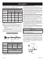
GAS SUPPLY
The gas pipeline can be brought in through the right or left side of
the appliance. Consult the current National Fuel Gas Code, ANSI
Z223.1 CAN/CGA-B149 (.1 or .2) installation code.
Recommended Gas Pipe Diameter
Pipe
Length
Schedule 40 Pipe
Inside Diameter
Tubing, Type L
Outside Diameter
Natural Propane Natural Propane
0-10ft
0-3m
1/2"
12.7mm
3/8"
9.5mm
1/2"
12.7mm
3/8"
9.5mm
11-40ft
4-12m
1/2"
12.7mm
1/2"
12.7mm
5/8"
15.9mm
1/2"
12.7mm
41-100ft
13-30m
1/2"
12.7mm
1/2"
12.7mm
3/4"
19mm
1/2"
12.7mm
101-150ft
31-46m
3/4"
19mm
1/2"
12.7mm
7/8"
22.2mm
3/4"
1.9 mm
NOTICE: Never use plastic pipe. Check to conrm whether your
local codes allow copper tubing or galvanized.
NOTICE: Since some municipalities have additional local codes, it
is always best to consult your local authority and installation code.
The use of the following gas connectors is recommended:
— ANS Z21.24 Appliance Connectors of Corrugated Metal Tubing
and Fittings.
— ANS Z21.45 Assembled Flexible Appliance Connectors of Other
Than All-Metal Construction
The above connectors may be used if acceptable by the authority
having jurisdiction. The Commonwealth of Massachusetts requires
that a exible appliance connector cannot exceed three feet in length.
FLEXIBLE GAS LINE CONNECTION
GAS SUPPLY
TEE HANDLE
FLEX TUBING
FLARE FITTING FLARE SHUT
OFF VALVE
Figure 8
Gas Supply Pressure (inches w.c.)
Minimum Normal Maximum
Natural Gas 4.5" 7.0" *14.0"
Propane Gas 10.8" 11.0" *14.0"
Manifold Pressure (inches w.c.)
Normal (HI)
Natural Gas 3.5"
Propane Gas 10.0"
*NOTE: Remote “RF” Models - 10.5” w.c. maximum
Installing a New Main Gas Shut-Off
Each appliance should have its own manual gas shut-off.
A manual main gas shut-off should be located in the vicinity of the
unit. Where none exists, or where its size or location is not adequate,
contact your local authorized installer for installation or relocation.
Compounds used on threaded joints of gas piping shall be resistant
to the action of liqueed petroleum gases. The gas lines must be
checked for leaks by the installer. This should be done with a soap
solution watching for bubbles on all exposed connections, and if
unexposed, a pressure test should be made.
Never use an exposed ame to check for leaks. Appliance must
be disconnected from piping at inlet of control valve and pipe
capped or plugged for pressure test. Never pressure test with
appliance connected; control valve will sustain damage!
NOTICE: The millivolt gas controls are equipped with a captured
screw type pressure test point, therefore it is not necessary to
provide a 1/8” test point up stream of the control.
On direct ignition valves, hex plugs may be replaced with hose ttings
for pressure checks, then reinstalled before operating replace.
When using copper or ex connector use only approved ttings.
The appliance and it’s individual shut off valve must be disconnected
from supply piping system during any pressure testing of that system
at test pressures in excess of 1/2 psig (3.5kPa).
The appliance must be isolated from the gas supply piping system
by closing its individual manual shut off valve during any pressure
testing of the gas supply piping system at test pressures equal to
or less than 1/2 psig (3.5kPa).
CAUTION
If one of the procedures results in pressures in excess of
1/2 psig (14” w.c.) (3.5 kPa) on the replace gas valve, it will
result in a hazardous condition.
Checking Manifold Pressures
Both Propane and Natural Gas valves have a built-in pressure
regulator in the gas valve. Natural Gas models will have a manifold
pressure of approximately 3.5” w.c. (.871kPa) at the valve outlet
with the inlet pressure to the valve from a minimum of 4.5” w.c.
(1.120kPa) for the purpose of input adjustment to a maximum of
14.0” w.c. (3.484kPa). Propane Gas models will have a manifold
pressure approximately 10.0” w.c. (2.49kPa) at the valve outlet
with the inlet pressure to the valve from a minimum of 10.8” w.c.
(2.68kPa) for the purpose of input adjustment to a maximum of
14.0” w.c. (3.484kPa).
GAS LINE HOLE
(BOTH SIDES)
2”
10”
FROM FRONT OF
APPLIANCE TO
GAS LINE HOLE
Figure 9

39359-0-1018 Page 13
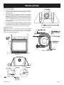
INSTALLATION
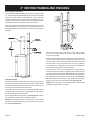
Framing and Finishing
1. Choose unit location.
2. Frame in replace with a header across the top. It is important
to allow for nished face when setting the depth of the frame.
See Figure 10B.
3. Attach replace to frame using nailing ange. Preset depth to
suit facing material (adjustable to 1/2”, 5/8” or 3/4” depths).
NOTICE: Fireplace must mount ush to facing material. If facing
material requires more depth than 3/4”, mark and drill two 1/8”
holes into replace side at appropriate depth. Bend standoff
tabs as needed to move replace ush with facing material.
See Figure 10A.
4. Use eight 1/2” hex-head screws supplied in hardware package,
to screw through slotted holes in nailing ange and then screw
into pre-drilled holes on replace side. Measure from face of
replace to face of nailing ange to determine nal depth.
Vent Pipe Clearance
NOTE: Maintain one inch of clearance around top vent pipe. See
Figure 11. For rear vent, maintain a minimum 1” clearance to the
bottom and sides of the vent, and 3” clearance to combustibles
above the vent pipe. See Figure 12.
Figure 10A
Figure 10B
Figure 11 - Top Vent
Figure 12 - Rear Vent

39359-0-1018Page 14
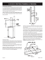
INSTALLATION (CONT'D)
Flush Mount Mantel Installation
The replace must extend 3/4” beyond nished wall surface when
using a ush mount mantel. Refer to Figure 13 to locate nailing
anges on replace sides. Mark and drill two 1/8” holes into replace
side to mount each nailing ange. Use eight 1/2” hex-head screws
supplied in hardware package to attach nailing anges to replace
sides.
Figure 13
Attention: When replace is installed in optional full cabinet mantel
or corner mantel the four nailing anges shown in Figure 10A will
not be installed on the side of outer casing. The replace will be
attached to the full cabinet mantel or corner mantel with the two
nailing anges located on the top of the outer casing assembly.
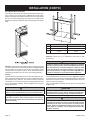
Framing
Fireplace framing can be built before or after the replace is set in
place. Framing should be positioned to accommodate wall covering
and replace facing material. The replace framing should be
constructed of 2 x 4 lumber or heavier. The framing headers may
rest on the replace standoffs. Refer to Figure 14 for minimum
framing dimensions.
CAUTION
Measure replace dimensions and verify framing methods,
and wall covering details before framing construction begins.
Framing dimension "A" includes a three inch clearance for
standoffs on rebox. After installing rebox into framing,
the nished wall surface must cover the three inch opening
above the rebox.
DVP42 DVP48
"A" 37 3/4" 37 3/4"
"B" 43 3/8" 49 3/8"
"C" 19 7/8" 19 7/8"
Figure 14
Attention: Add 3-3/4” to “A” dimensions when using a ush
mantel base.
WARNING
If a base or mantel is not used and the appliance is installed
directly on carpeting, tile or other combustible material other
than wood ooring, it shall be installed on a metal or wood
panel extending the full width and depth of the appliance.
The vertical dimension in Figure 14 must be adjusted when
a metal or wood panel is placed beneath the appliance.
Finishing
Finish the walls with the material of your choice. Figure 5 on page 10
shows the minimum vertical and corresponding maximum horizontal
dimensions of mantels or other combustible projections above the
top front edge of the replace.
Only non-combustible materials may be used to cover the black
replace front.
WARNING
When nishing the replace never obstruct or modify the air
inlet/outlet louvers in any manner. Provide adequate clear-
ances around air openings into the combustion chamber.
CAUTION
If the joints between the nished wall and the replace sur-
round (top and sides) are sealed, a 300°F minimum sealant
material must be used. These joints are not required to be
sealed. Only non-combustible material (using 300°F mini-
mum adhesive if needed), can be applied as facing to the
replace surround.

39359-0-1018 Page 15
INSTALLATION (CONT'D)
Flush Wall Installation
Figure 15
Combustible Surround Installation
Figure 16
NOTICE: For mantelshelf requirements, see Figure 5 on page
Attention: Cold climate installation recommendation:
When installing this unit against a non-insulated exterior
wall, it is recommended that the outer walls be insulated to
conform to applicable insulation codes.
Vent Runs
In planning the installation for the replace, it is necessary to install
certain components before the appliance is completely positioned
and installed. These include the direct vent system, gas piping for
the appliance and the electrical wiring. (If the fan option is used.)
The appliance can be mounted on any of the following surfaces:
1. A at, hard combustible (burnable) surface.
2. A raised wooden platform.
3. Four corner supports. (Example: Four concrete masonry blocks.)
These supports must be positioned so they contact all four
perimeter edges on the bottom of the unit (if allowed by local
codes).
NOTICE: Discard insulation and retainer when venting from the
top of the replace.
TOP, 90° ELBOW WITH HORIZONTAL TERMINATION
Figure 17

39359-0-1018Page 16
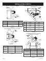
INSTALLATION (CONT'D)
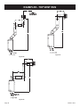
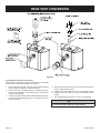
REAR ONLY, STRAIGHT OUT THE BACK
"A" "B" MODEL
6"(152mm) 5 1/8"(130mm) to 6 /2"(165mm) DVP 42,48
9"(229mm) 8 1/8"(206mm) to 91/2"(241mm) DVP 42
12"(305mm)
11 1/8"(283mm) to 12 1/2"
(317mm)
DVP 42
Figure 18
TOP, 90° ELBOW TO HORIZONTAL OUT THE WALL
"A" "B" "C"
6"(152mm)
11 1/4"(286mm) to
12 3/4"(324mm)
4 3/4"(121mm) to
6 1/4"(159mm)
9"(229mm)
14 1/4"(362mm) to
15 3/4"(400mm)
7 3/4"(197mm) to
9 1/4"(235MM)
12"(305mm)
17 1/4"(438mm) to
18 3/4"(476mm)
10 3/4"(273mm) to
12 1/4"(311mm)
Figure 19
CORNER INSTALLATION TOP, 90° ELBOW TO HORIZONTAL
OUT THE WALL
Dim. DVP42 DVP48
A
45 3/8"
1152mm
49 5/8"
1260mm
B
32 1/8"
816mm
35 1/8"
892mm
C
13 3/8"
34 mm
15 1/2"
39 mm
D
64 1/8"
1628mm
70 1/8"
1781mm
Figure 20
CORNER INSTALLATION REAR, 45° ELBOW
TO HORIZONTAL OUT THE WALL
DVP42 DVP48
"A" "B" "B"
6"(152mm)
4"(102mm) to
5 1/2"(140mm)
4"(102mm) to
5"(127mm)
9"(229mm)
6"(152mm) to
7 /2"(191mm)
6"(152mm) to
7 1/2"(191mm)
12"(305mm)
9"(229mm) to
10 1/2"(267mm)
9"(229mm) to
10 1/2"(267mm)
Figure 21

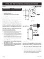
39359-0-1018 Page 17
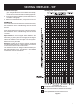
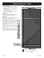
To Use the Vent Graph
1. Determine the height of the center of the horizontal vent
pipe. Using this dimension on the Sidewall Vent Graph,
locate the point it intersects with the slanted graph line.
2. From the point of this intersection, draw a vertical line to
the bottom of the graph.
3. Select the indicated dimension, and position the unit in
accordance with same.
EXAMPLE A:
If the vertical dimension from the oor of the unit is 35 feet,
the horizontal run to the outer wall ange must not exceed
6.5 feet.
EXAMPLE B:
If the vertical dimension from the oor of the unit is 6.5 feet,
the horizontal run to the outer wall ange must not exceed
14.5 feet.
Special Note: For each 45 degree elbow installed in the
horizontal run, the length of the horizontal run MUST be
reduced by 18" (45cm). This does not apply if the 45 degree
elbows are installed on the vertical part of the vent system.
Reduce 3' for every 90° elbow.
Example: According to the chart the maximum horizontal
vent length is 20' and if two 45 degree elbows are required
in the horizontal vent it must be reduced to 17'.
The maximum number of 45 degree elbows permitted per
side wall installation is two. These elbows can be installed
in either the vertical or horizontal run.
NOTE: On vertical venting the rst elbow does not get counted.
Acceptable vertical and horizontal vent run.
(40' maximum vertical and 20' maximum horizontal)
Unacceptable vertical and horizontal vent run.
Figure 22
Venting Graph (Dimensions in Feet)
VENTING FIREPLACE - TOP

39359-0-1018Page 18
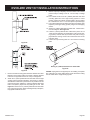
VENTING FIREPLACE - TOP (CONT'D)
Below Grade Installation
When it is not possible to meet the required vent terminal clearances
of 12” (305mm) above grade level, a snorkel kit is recommended.
It allows installation depth down to 7” (178mm) below grade level.
The 7” (178mm) is measured from the center of the horizontal vent
pipe as it penetrates through the wall.
Ensure the sidewall venting clearances are observed. If venting
system is installed below ground, we recommend a window
well with adequate and proper drainage to be installed around
the termination area.
TYPICAL BASEMENT INSTALLATION
Figure 23
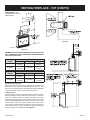
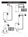
Examples of possible venting systems using one 90° elbow. Eight
feet is listed as minimum vertical vent run with 20 feet of maximum
horizontal vent run. Vertical dimensions are based on centerline to
centerline of pipe. Horizontal dimensions are based on centerline
of pipe to end of termination.
Figure 24
Examples of possible venting systems using two 90° elbows.
V is listed as minimum vertical dim ensions and H1 + H2 is
listed as total of maximum horizontal dimensions. The maximum
vertical and horizontal distances for two 90° elbows as shown in
Figure 25 is 20 feet.
Attention: Refer to Figure 22 for additional venting requirements.
Figure 25

39359-0-1018 Page 19
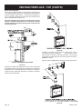
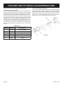
Figure 26
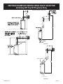
MINIMUM HOLE LOCATION DIMENSIONS FOR THROUGH THE
WALL HORIZONTAL INSTALLATIONS WITH 90 DEGREE ELBOW
OFF TOP OF FIREPLACE
FIREPLACE
SERIES
HARD ELBOW DIMENSIONS
"A" "B" "C"
DVP42FP
43-1/2"
(1105mm)
5" (127mm)
7"
(178mm)
DVP48FP
43-1/2"
(1105mm)
5" (127mm)
7"
(178mm)
FIREPLACE
SERIES
FLEX PIPE 90 DEGREE BEND
"A" "B" "C"
DVP42FP
46"
(1143mm)
5" (127mm) 7" (178mm)
DVP48FP
46"
(1143mm)
5" (127mm)
7"
(178mm)
Positioning the Fireplace
Determine the exact position of the appliance so the direct vent
termination will be centered (if possible) between two studs. This
will avoid any extra framing. All vent kit pipes should be assembled
on the unit after the unit is moved into the nal position.
Cutting the Hole
After the replace has been positioned in its permanent location,
the hole through the exterior wall of the house can be cut. This hole
must be 12” (305mm) high x 10” (254mm) wide with its center line
determined by the amount of vertical rise and horizontal run of the
termination. See Figure 26. When locating the hole it must be noted
that the bottom of the cap must be 12” (305mm) above the ground
level, and top of the cap must be no less than 18” (457mm) below a
combustible projection, and no closer than 9” (229mm) to any wall
running parallel to vent termination. See Figure 27.
Figure 27
Figure 28
SEE FIGURE 22 FOR
PERMISSIBLE “H” AND “V”
DIMENISONS.
VENTING FIREPLACE - TOP (CONT'D)

39359-0-1018Page 20
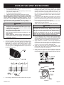
Figure 30
Figure 31
EXAMPLES - TOP VENT RUN
Figure 29
Page is loading ...
Page is loading ...
Page is loading ...
Page is loading ...
Page is loading ...
Page is loading ...
Page is loading ...
Page is loading ...
Page is loading ...
Page is loading ...
Page is loading ...
Page is loading ...
Page is loading ...
Page is loading ...
Page is loading ...
Page is loading ...
Page is loading ...
Page is loading ...
Page is loading ...
Page is loading ...
Page is loading ...
Page is loading ...
Page is loading ...
Page is loading ...
Page is loading ...
Page is loading ...
Page is loading ...
Page is loading ...
Page is loading ...
Page is loading ...
Page is loading ...
Page is loading ...
Page is loading ...
Page is loading ...
Page is loading ...
Page is loading ...
Page is loading ...
Page is loading ...
Page is loading ...
Page is loading ...
Page is loading ...
Page is loading ...
Page is loading ...
Page is loading ...
Page is loading ...
Page is loading ...
Page is loading ...
Page is loading ...
Page is loading ...
Page is loading ...
Page is loading ...
Page is loading ...
Page is loading ...
Page is loading ...
Page is loading ...
Page is loading ...
Page is loading ...
Page is loading ...
Page is loading ...
Page is loading ...
Page is loading ...
Page is loading ...
Page is loading ...
Page is loading ...
-
 1
1
-
 2
2
-
 3
3
-
 4
4
-
 5
5
-
 6
6
-
 7
7
-
 8
8
-
 9
9
-
 10
10
-
 11
11
-
 12
12
-
 13
13
-
 14
14
-
 15
15
-
 16
16
-
 17
17
-
 18
18
-
 19
19
-
 20
20
-
 21
21
-
 22
22
-
 23
23
-
 24
24
-
 25
25
-
 26
26
-
 27
27
-
 28
28
-
 29
29
-
 30
30
-
 31
31
-
 32
32
-
 33
33
-
 34
34
-
 35
35
-
 36
36
-
 37
37
-
 38
38
-
 39
39
-
 40
40
-
 41
41
-
 42
42
-
 43
43
-
 44
44
-
 45
45
-
 46
46
-
 47
47
-
 48
48
-
 49
49
-
 50
50
-
 51
51
-
 52
52
-
 53
53
-
 54
54
-
 55
55
-
 56
56
-
 57
57
-
 58
58
-
 59
59
-
 60
60
-
 61
61
-
 62
62
-
 63
63
-
 64
64
-
 65
65
-
 66
66
-
 67
67
-
 68
68
-
 69
69
-
 70
70
-
 71
71
-
 72
72
-
 73
73
-
 74
74
-
 75
75
-
 76
76
-
 77
77
-
 78
78
-
 79
79
-
 80
80
-
 81
81
-
 82
82
-
 83
83
-
 84
84


American Hearth Madison Premium Fireplace (DVP42FP & DVP48FP) Owner's manual
- Category
- Fireplaces
- Type
- Owner's manual
- This manual is also suitable for
Ask a question and I''ll find the answer in the document
Finding information in a document is now easier with AI
Related papers
-
White Mountain Hearth Tahoe Premium Fireplace (DVP42FP & DVP48FP) Owner's manual
-
-
-
-
-
-
-
-
-
Other documents
-
Monessen Hearth MDV600 User manual
-
 Lennox Hearth Products LSM40MN-2 User manual
-
Montigo RFKFID User manual
-
Fanimation Fitzgerald Owner's manual
-
Empire Heating Systems DV-35-2SG Owner's manual
-
Lennox MPE-36R User manual
-
-
FMI CD36RC-1WS Operating instructions
-
Builders Edge 130120002013 Installation guide
-
FMI MPE-33R User manual
