Page is loading ...

COPYRIGHT © FEBRUARY, 2015 BY GRIZZLY INDUSTRIAL, INC. REVISED JANUARY, 2018 (AB)
WARNING: NO PORTION OF THIS MANUAL MAY BE REPRODUCED IN ANY SHAPE
OR FORM WITHOUT THE WRITTEN APPROVAL OF GRIZZLY INDUSTRIAL, INC.
(FOR MODELS MANUFACTURED SINCE 01/15) #BB17235 PRINTED IN TAIWAN
The Model G0441HEP is the same machine as the Model G0441 except for the dual-filtration HEPA filter
system and the included stand. Except for the differences noted in this insert, all other content in the Model
G0440/G0441 owner's manual applies to this machine.
: To reduce the risk of serious injury, you MUST read and understand this insert—and
the entire Model G0440/G0441 manual—BEFORE assembling, installing, or operating this machine!
If you have any further questions about this manual insert or the differences between the Model G0441HEP
and the Model G0441, contact our Technical Support at (570) 546-9663 or email [email protected].
MODEL G0441HEP
3 HP DUAL-FILTRATION HEPA
CYCLONE DUST COLLECTOR
MANUAL INSERT
(For owner's manual revised October, 2013)
V1.01.18

-2-
Model G0442HEP/G0601HEP (Mfd. Since 01/15)Model G0441HEP (Mfd. Since 01/15)
The information contained herein is deemed accurate as of 2/5/2018 and represents our most recent product specifications.
Due to our ongoing improvement efforts, this information may not accurately describe items previously purchased.
PAGE 1 OF 3
Model G0441HEP
MACHINE DATA
SHEET
Customer Service #: (570) 546-9663 · To Order Call: (800) 523-4777 · Fax #: (800) 438-5901
MODEL G0441HEP 3 HP DUAL‐FILTRATION HEPA
CYCLONE DUST COLLECTOR
Product Dimensions:
Weight.............................................................................................................................................................. 514 lbs.
Width (side-to-side) x Depth (front-to-back) x Height............................................................. 60-3/4 x 33 x 107-1/2 in.
Footprint (Length x Width)..................................................................................................................... 60-3/4 x 33 in.
Shipping Dimensions:
Carton #1
Type.............................................................................................................................. Cardbord Box on Pallet
Content................................................................................................................................................. Machine
Weight.................................................................................................................................................... 353 lbs.
Length x Width x Height............................................................................................................. 53 x 28 x 35 in.
Carton #2
Type........................................................................................................................................... Cardboard Box
Content............................................................................................................................ HEPA Filter Cartridge
Weight.................................................................................................................................................... 117 lbs.
Length x Width x Height............................................................................................................. 45 x 27 x 35 in.
Carton #3
Type........................................................................................................................................... Cardboard Box
Content............................................................................................................................... HEPA Filter Adapter
Weight...................................................................................................................................................... 22 lbs.
Length x Width x Height............................................................................................................. 33 x 15 x 11 in.
Carton #4
Type........................................................................................................................................... Cardboard Box
Content...................................................................................................................................................... Stand
Weight...................................................................................................................................................... 86 lbs.
Length x Width x Height............................................................................................................... 40 x 14 x 7 in.
Electrical:
Power Requirement........................................................................................................... 220V, Single-Phase, 60 Hz
Full-Load Current Rating........................................................................................................................................ 22A
Minimum Circuit Size.............................................................................................................................................. 40A
Connection Type........................................................................................... Permanent (Hardwire to Shutoff Switch)
Switch Type......................................................................... Remote Control Magnetic Switch w/Overload Protection
Motors:
Main
Horsepower................................................................................................................................................ 3 HP
Phase............................................................................................................................................ Single-Phase
Amps............................................................................................................................................................ 22A
Speed................................................................................................................................................ 3450 RPM
Type.................................................................................................. TEFC Capacitor-Start Induction (Class F)
Power Transfer ............................................................................................................................... Direct Drive
Bearings..................................................................................................... Shielded & Permanently Lubricated

Model G0441HEP (Mfd. Since 01/15)
-3-
The information contained herein is deemed accurate as of 2/5/2018 and represents our most recent product specifications.
Due to our ongoing improvement efforts, this information may not accurately describe items previously purchased.
PAGE 2 OF 3
Model G0441HEP
Main Specifications:
Operation
Dust Collector Type.......................................................................................................... Two-Stage (Cyclone)
Approved Dust Types................................................................................................................................ Wood
Filter Type.......................................................................................................................... Cartridge and HEPA
Airflow Performance..................................................................................................... 1654 CFM @ 2.0 in. SP
Max Static Pressure (at 0 CFM)............................................................................................................. 14.2 in.
Main Inlet Size............................................................................................................................................. 8 in.
Inlet Adapter Included.................................................................................................................................... No
Machine Collection Capacity At One Time....................................................................................................... 3
Maximum Material Collection Capacity................................................................................................ 7.4 cu. ft.
Filtration Rating................................................................................................................ 99.97% @ 0.3 Micron
Filter Surface Area.............................................................................................................................. 113 sq. ft.
Bag Information
Number of Lower Bags..................................................................................................................................... 1
Lower Bag Diameter............................................................................................................................ 19-3/4 in.
Canister Information
Number of Canister Filters................................................................................................................................ 1
Canister Filter Diameter................................................................................................................... 19-11/16 in.
Canister Filter Length.......................................................................................................................... 46-1/4 in.
Collection Drum Size......................................................................................................................... 55 Gallons
Impeller Information
Impeller Type...................................................................................................................................... Radial Fin
Impeller Size........................................................................................................................................ 15-1/2 in.
Construction
Lower Bag...................................................................................................................................... Clear Plastic
Canister............................................................................................................................ Spun Bond Polyester
Frame....................................................................................................................... Steel Sheet Metal (14 ga.)
Impeller....................................................................................................................................................... Steel
Paint Type/Finish....................................................................................................................... Powder Coated
Blower Housing......................................................................................................................... 11-Gauge Steel
Body.......................................................................................................................................... 14-Gauge Steel
Collection Drum.......................................................................................................................................... Steel
Other Specifications:
Country of Origin .............................................................................................................................................. Taiwan
Warranty ........................................................................................................................................................... 1 Year
Approximate Assembly & Setup Time ............................................................................................................. 4 Hours
Serial Number Location .................................................................................................................................. ID Label
Sound Rating ............................................................................................................................................. 79 – 80 dB
ISO 9001 Factory .................................................................................................................................................. Yes
Certified by a Nationally Recognized Testing Laboratory (NRTL) ......................................................................... Yes

-4-
Model G0441HEP (Mfd. Since 01/15)
Inventory
The following is a description of the main compo-
nents shipped with your machine. Lay the compo-
nents out to inventory them.
Inventory (Figure 1) Qty
A. Intake Cylinder ........................................... 1
B. Cyclone Funnel .......................................... 1
C. Intake Barrel ............................................... 1
D. Drum Collection Bags ................................ 1
E. Motor/Blower Housing Assembly ............... 1
F. Upper Collection Drum ............................... 1
G. Lower Collection Drum ............................... 1
H. Clear Flexible Hose 9" x 13"....................... 1
I. Hose Clamps 9" ......................................... 2
J. Collection Drum Lid .................................... 1
K. Collection Drum Seal ................................. 1
L. Foam Tape Roll 3 x 6mm .......................... 1
M. Barrel Gaskets ............................................ 2
N. Outlet Gasket ............................................. 1
O. Hose Clamps 1
1
⁄4" ...................................... 2
P. Vacuum Hose 1
1
⁄4" x 98" ............................ 1
Q. Collection Drum Vacuum Ring ................... 1
R. Cyclone Vacuum Tube ............................... 1
S. Vacuum Hose Clips .................................... 2
Figure 1. Model G0441 inventory.
F
C
B
A
D
E
L
J
I
G
H
N
Q
P
R
S
K
M
O

Model G0441HEP (Mfd. Since 01/15)
-5-
Figure 2. Contents of filter boxes.
T
U
V
X
W
T. Canister/HEPA Filter Assembly ................. 1
U. Filter Adapter .............................................. 1
V. Adapter Gasket ........................................... 1
W. Collection Bag ............................................ 1
X. Canister Brackets ....................................... 4
Hardware (not shown) Qty
Y. Hardware Box
—Phillips Head Screws #10-24 x
3
⁄8" ........ 12
—Hex Nuts #10-24 ................................... 12
—Drum Latches ......................................... 3
—Roll of Foam Tape 5 x 50mm ................. 1
—Hex Bolts
3
⁄8"-16 x 1" ............................... 8
—Hex Nuts
3
⁄8"-16 ....................................... 4
—Flat Washers
3
⁄8" .................................... 24
—Lock Washers
3
⁄8" .................................... 4
—Lock Nuts
3
⁄8" .......................................... 8
—Hex Bolts
5
⁄16"-18 x 1" ............................ 20
—Hex Bolts
5
⁄16"-18 x
3
⁄4" ........................... 20
—Flat Washers
5
⁄16" ................................... 52
—Hex Nuts
5
⁄16"-18 .................................... 20
—Casters ................................................... 4
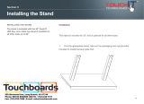
Stand Box Contents (Figure 3) Qty
AA. Lower Stand Legs ..................................... 4
AB. Upper Stand Legs ..................................... 4
AC. Upper Stand Braces .................................. 4
AD. Lower Stand Braces .................................. 4
AE. Collector Mounting Brackets ..................... 4
AF. Hardware Bag
—Hex Bolts
3
⁄8"-16 x
3
⁄4" ............................ 67
—Lock Nuts
3
⁄8"-16 .................................... 64
—Flat Washers
3
⁄8" .................................. 134
—Hex Nuts
3
⁄8"-16 ....................................... 3
—Hex Bolts
5
⁄16"-18 x 1" .............................. 8
—Lock Nuts
5
⁄16"-16 ..................................... 8
—Flat Washers
5
⁄16" ................................... 16
— Vacuum Hose Clips ................................ 2
Figure 3. Contents of stand box.
AA
AB
AC
AD
AE
AF

-6-
Model G0442HEP/G0601HEP (Mfd. Since 01/15)Model G0441HEP (Mfd. Since 01/15)
The HEPA cyclones are assembled largely the
same way as the regular cyclones but with the
HEPA filter components being installed in place of
the regular canister filter assembly. To assemble
your HEPA cyclone, open the Assembly section
in the Owner's Manual and follow those steps only
when specified below.
There are two options to consider when assem-
bling your HEPA cyclone. You can assemble it
with the included stand, or if shop space is limited,
you can mount it to the wall by purchasing the
optional T27326 Wall-Mount Adapter Kit.
Assembly
To ensure the integrity of the HEPA filtration
system and prevent fine dust from leaking
out before it reaches the filters, we strongly
recommend using a general-purpose sili-
cone sealant on all mating surfaces dur-
ing the assembly process. For those com-
ponents assembled with a rubber gasket
between them, apply the sealant evenly on
both sides of the gasket before assembly.
Tools Needed: Qty
Wrenches or Sockets
9
⁄16" .................................. 2
Wrenches or Sockets
1
⁄2" ................................... 2
90° Square ........................................................ 1
Assistants for Lifting ...................................2 or 3
To assemble dust collector:
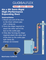
1. Connect upper stand legs with lower braces
using (16)
3
⁄8"-16 x
3
⁄4" hex bolts, (32)
3
⁄8"
flat washers, and (16)
3
⁄8"-16 lock nuts (see
Figure 4)—only finger-tighten for now.
Figure 4. Initial assembly of upper stand legs
connected to lower stand braces.
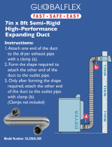
2. Attach upper stand braces to the assem-
blyusing (16)
3
⁄8"-16 x
3
⁄4" hex bolts, (32)
3
⁄8"
flat washers, and (16)
3
⁄8"-16 lock nuts (see
Figure 5). Note: Attach braces to the lower
mounting position to fit under an 8' ceiling.
Assembling with Stand
x 16
Upper
Stand
Leg
Lower
Brace
Figure 5. Upper braces attached to stand
assembly.
3. Flip stand assembly upside down and install
lower legs using (24)
3
⁄8"-16 x
3
⁄4" hex bolts,
(48)
3
⁄8" flat washers, and (24)
3
⁄8"-16 lock nuts
(see Figure 6).
Figure 6. Lower legs attached to stand
assembly.
x 16
Lower
Legs
Higher
Mounting
Position
Lower
Mounting
Position
Upper
Brace
x 24

Model G0441HEP (Mfd. Since 01/15)
-7-
4. Square up the stand, as shown in Figure 7,
and tighten all nuts and bolts.
Figure 7. Squaring stand assembly before
tightening stand hardware.
5. Apply foam seal tape on intake barrel, intake
cylinder, cyclone barrel, and outlet port, as
shown in Figure 8.
Figure 8. Foam seal tape applied to necessary
components.
6. Place motor/blower housing on a large piece
of cardboard to prevent scratches.
7. Attach intake cylinder to bottom of housing,
as shown in Figure 9, using (4)
5
⁄16"-18 x
3
⁄4"
hex bolts, (4)
5
⁄16" flat washers, and (4)
5
⁄16"-18
lock nuts.
Note: Because this part of the dust collector
is not accessible after assembly, consider
using Medium Strength Blue Thread Locker
on the bolts that secure the intake cylinder
to the motor/blower housing assembly to
ensure that the fasteners won't come loose
with vibration.
8. Attach intake barrel to blower housing, as
shown in Figure 10, with (12)
5
⁄16"-18 x
3
⁄4"
hex bolts, (12)
5
⁄16" flat washers, and (12)
5
⁄16"-
18 lock nuts.
Figure 10. Securing blower on intake barrel.
90° Square
Foam Tape
Figure 9. Intake cylinder attached to the bottom
of motor housing.
Motor/Blower
Housing
Intake
Cylinder
x 4
Intake
Barrel
x 12

-8-
Model G0442HEP/G0601HEP (Mfd. Since 01/15)Model G0441HEP (Mfd. Since 01/15)
Figure 11. Cyclone funnel attached to intake
barrel.
10. Attach (4) collector mounting brackets to
intake assembly, as shown in Figure 12,
using (8)
5
⁄16"-18 x 1" hex bolts, (16) flat wash-
ers, and (8) lock nuts.
11. Lay stand assembly on its side, on a large
piece of cardboard to prevent scratches,
and slide the collector assembly into stand
assembly.
12. Fasten the collector assembly to the stand
with (8)
3
⁄8"-16 x 1" hex bolts, (16)
3
⁄8" flat
washers, and (8)
3
⁄8"-16 lock nuts, as shown
in Figure 13.
Figure 13. Collector assembly fastened to the
stand.
Figure 14. Lifting the assembly upright.
13. Pivot the dust collector upright by having two
or three strong helpers lift motor end while
one person keeps the stand end from sliding
or rocking.
Cyclone
Funnel
9. Attach cyclone funnel to intake barrel, as
shown in Figure 11, with (12)
5
⁄16"-18 x 1" hex
bolts, (24)
5
⁄16" flat washers, and (12)
5
⁄16"-18
lock nuts.
Note: At the places where you see three
holes in a row, only use the center hole for
this step. The two outside holes will be used
in the next step.
x 8
Figure 12. Collector mounting brackets attached
to intake assembly.
Collector
Mounting
Bracket
x 8
x 12

Model G0441HEP (Mfd. Since 01/15)
-9-
18. Attach rubber gasket to blower housing (see
Figure 18), then secure HEPA filter assem-
bly using (8)
3
⁄8"-16 x 1" hex bolts, (8)
3
⁄8" hex
nuts and (16)
3
⁄8" flat washers.
16. Follow assembly instruction Steps 10 in own-
ers manual.
17. Attach rubber gasket to top of HEPA filter
housing (see Figure 17), then secure filter
adapter to housing using (8)
5
⁄16"-18 x 1" hex
bolts and (8)
5
⁄16" flat washers.
Figure 17. Attaching filter adapter to filter
housing.
Rubber
Gasket
Filter Adapter
Filter
Housing
x 8
Figure 18. Attaching HEPA filter assembly to
blower housing.
HEPA Filter
Assembly
x 8
Rubber Gasket
19. Follow assembly Steps 14–21 in Owner's
Manual to assemble collection drum.
14. Pull off front cover of the switch box, remove
remote control and spare grommets, and
push front cover back on.
15. Mount switch bracket on the stand, as shown
in Figure 15, with (2)
3
⁄8"-16 x
3
⁄4" hex bolts,
(4)
3
⁄8" flat washers, and (2)
3
⁄8"-16 lock nuts.
Figure 16. Securing vacuum hose to stand legs.
U-Shaped
Clips
16. Secure vacuum hose inside upper and lower
stand legs with (2) U-shaped clips (see
Figure 16).
Figure 15. Switch bracket mounted to stand.
x 2

-10-
Model G0442HEP/G0601HEP (Mfd. Since 01/15)Model G0441HEP (Mfd. Since 01/15)
1. Follow Steps 1–5 in Assembly section,
beginning on Page 19 of Owner's Manual.
In Step 5, replace original intake barrel
brace with the extended brace provided with
T27326 Wall-Mount Adapter Kit for HEPA
Upgrade (see Figure 21).
Assembling with Wall-Mount Option
Figure 21. Extended brace included with T27326
wall-mount kit.
2. Follow assembly Steps 6–10 in Owner's
Manual.
3. Attach adapter gasket and wall-mount adapt-
er using (8)
3
⁄8"-16 x 1" hex bolts, (8)
3
⁄8" hex
nuts, and (16)
3
⁄8" flat washers (see Figure 22).
Figure 22. Attaching wall-mount adapter.
Wall-Mount
Adapter
x 8
Adapter
Gasket
21. Double-check that all nuts and bolts are
tightened. Congratulations, the assembly is
complete.
Figure 20. G0441HEP filter system completely
installed.
Figure 19. Installing collection bag under HEPA
filter.
20. Slip plastic collection bag around opening
under canister filter, and secure with metal
bag clamp (see Figure 19).

Model G0441HEP (Mfd. Since 01/15)
-11-
8. Double-check that all nuts and bolts are
tightened. Congratulations, the assembly is
complete.
Figure 26. G0441HEP wall-mount filter system
completely installed.
5. Attach rubber gasket to wall-mount adapter
(see Figure 24), then secure HEPA filter
assembly using (8)
3
⁄8"-16 x 1" hex bolts, (8)
3
⁄8" hex nuts and (16)
3
⁄8" flat washers.
Figure 24. Attaching HEPA filter assembly to
wall-mount adapter.
Rubber
Gasket
HEPA Filter
Assembly
7. Slip plastic collection bag around opening
under canister filter, and secure with metal
bag clamp (see Figure 25).
Figure 25. Installing collection bag under HEPA
filter assembly.
Bag Clamp
Plastic
Collection
Bag
x 8
6. Follow assembly Steps 14–21 in Owner's
Manual to assemble collection drum.
Figure 23. Attaching filter adapter to filter
housing (wall-mount).
4. Attach rubber gasket to top of HEPA filter
housing (see Figure 23), then secure filter
adapter to housing using (8)
5
⁄16"-18 x 1" hex
bolts and (8)
5
⁄16" flat washers.
Rubber
Gasket
Filter Adapter
Filter
Housing
x 8

-12-
Model G0442HEP/G0601HEP (Mfd. Since 01/15)Model G0441HEP (Mfd. Since 01/15)
Main
1
1-1
1-2
1-3
1-4
1-5
1-6
2
3
4
5
6
7
8
9
10
11
12
13
14
15
16
17
18
19
20
23
230-4
34
35
37
38
40
41
42
43
44
45
46
47
49
66
94
95
19
19
124
6
115
6
118
121
122
120
123
119
6
6
117
117
117
117
6
6
124
124
124
124
116
39
36
84
86
101
102
103
104
105
67
96
24
226
232A
231
221
225
230-1
230-5
227
6
8
48
48
3-1
3-2
3-3
3-4
1-9
1-7
1-10
1-8
120
8
6
6
6
21
21
221
229
228
228-1
223
224
221
230
230-2
230-3
50
51
52
53
54
55
56
57
58
59
60
61
62
63
64
65
106
107
108
109
110
111
112
113
114
64
53A
BUY PARTS ONLINE AT GRIZZLY.COM !
Scan QR code to visit our Parts Store.

Model G0441HEP (Mfd. Since 01/15)
-13-
Main Parts List
REF PART # DESCRIPTION REF PART # DESCRIPTION
1 P0441HEP001 MOTOR 3HP 220V 1-PH 55 P0441HEP055 HEX BOLT 5/16-18 X 3
1-1 P0441HEP001-1 MOTOR FAN COVER 56 P0441HEP056 HEX NUT 5/16-18
1-2 P0441HEP001-2 MOTOR FAN 57 P0441HEP057 DRUM LID LATCH ASSEMBLY
1-3 P0441HEP001-3 CAPACITOR COVER 58 P0441HEP058 PHLP HD SCR 10-24 X 3/8
1-4 P0441HEP001-4 S CAPACITOR 600M 125V 1-3/4 X 3-3/4 59 P0441HEP059 HEX NUT 10-24
1-5 P0441HEP001-5 R CAPACITOR 60M 300V 1-5/8 X 3-1/2 60 P0441HEP060 PHLP HD SCR 10-24 X 3/8
1-6 P0441HEP001-6 JUNCTION BOX 61 P0441HEP061 HEX NUT 10-24
1-7 P0441HEP001-7 BALL BEARING 6205ZZ 62 P0441HEP062 CASTER 2"
1-8 P0441HEP001-8 BALL BEARING 6203ZZ 63 P0441HEP063 HEX NUT 3/8-16
1-9 P0441HEP001-9 CONTACT PLATE 64 P0441HEP064 LOCK WASHER 3/8
1-10 P0441HEP001-10 CENTRIFUGAL SWITCH 3450 65 P0441HEP065 FLAT WASHER 3/8
2 P0441HEP002 MOTOR CORD 12G 3C 66 P0441HEP066 HEX BOLT 5/16-18 X 1
3 P0441HEP003 REMOTE MAG SWITCH 220V 67 P0441HEP067 FLAT WASHER 5/16
3-1 P0441HEP003-1 CONTACTOR NHD C-18D 220V 84 P0441HEP084 EXT TOOTH WASHER 3/8
3-2 P0441HEP003-2 OL RELAY NHD NTH-25 21–25A 86 P0441HEP086 MOTOR MOUNT GASKET
3-3 P0441HEP003-3 CIRCUIT BOARD 220V W/TRANSFORMER 94 P0441HEP094 JUNCTION BOX
3-4 P0441HEP003-4 ON/OFF SWITCH 110/220V 95 P0441HEP095 JUNCTION BOX CORD 12G 3C 12"
4 P0441HEP004 REMOTE CONTROLLER 96 P0441HEP096 GROUNDING WIRE 12G 6" (GREEN)
5 P0441HEP005 HEX BOLT 3/8-16 X 1-1/2 101 P0441HEP101 CYCLONE VACUUM TUBE
6 P0441HEP006 FLAT WASHER 3/8 102 P0441HEP102 FLAT WASHER 5/16
7 P0441HEP007 LOCK WASHER 3/8 103 P0441HEP103 HEX BOLT 5/16-18 X 3/4
8 P0441HEP008 HEX NUT 3/8-16 104 P0441HEP104 TUBE PLUG 1-1/4"
9 P0441HEP009 BLOWER COVER 105 P0441HEP105 FOAM TAPE 3 X 6 X 300MM
10 P0441HEP010 HEX BOLT 3/8-16 X 1-1/2 106 P0441HEP106 VACUUM HOSE 1-1/4" X 98"
11 P0441HEP011 FLAT WASHER 3/8 107 P0441HEP107 COLLECTION DRUM VACUUM TUBE
12 P0441HEP012 LOCK WASHER 3/8 108 P0441HEP108 FLAT WASHER 5/16
13 P0441HEP013 HEX NUT 3/8-16 109 P0441HEP109 HEX BOLT 5/16-18 X 3/4
14 P0441HEP014 IMPELLER 15-1/2" 110 P0441HEP110 HOSE CLAMP 1-1/4"
15 P0441HEP015 IMPELLER FENDER WASHER 3/8 111 P0441HEP111 TUBE PLUG 1-1/4"
16 P0441HEP016 HEX BOLT 3/8-16 X 1 LH 112 P0441HEP112 FOAM TAPE 3 X 6 X 300MM
17 P0441HEP017 FOAM TAPE 3 X 6 X 1600MM 113 P0441HEP113 COLLECTION DRUM VACUUM RING
18 P0441HEP018 BLOWER HOUSING 114 P0441HEP114 DRUM COLLECTION BAG 640 X 1200MM
19 P0441HEP019 FLAT WASHER 5/16 115 P0441HEP115 MOUNTING BRACKET
20 P0441HEP020 HEX BOLT 5/16-18 X 3/4 116 P0441HEP116 LOCK NUT 5/16-18
21 P0441HEP021 OUTLET GASKET 326 X 226MM 117 P0441HEP117 LOCK NUT 3/8-16
23 P0441HEP023 HEX BOLT 5/16-18 X 1 118 P0441HEP118 UPPER STAND BRACE
24 P0441HEP024 FLAT WASHER 5/16 119 P0441HEP119 UPPER STAND LEG
34 P0441HEP034 PLASTIC BAG 570 X 600MM 120 P0441HEP120 LOWER STAND BRACE
35 P0441HEP035 FOAM TAPE 3 X 6 X 1600MM 121 P0441HEP121 LOWER STAND LEG
36 P0441HEP036 INTAKE CYCLINDER 10" 122 P0441HEP122 STAND SWITCH BRACKET
37 P0441HEP037 HEX BOLT 5/16-18 X 3/4 123 P0441HEP123 VACUUM HOSE CLIP 2-1/2"
38 P0441HEP038 FLAT WASHER 5/16 124 P0441HEP124 HEX BOLT 3/8-16 X 3/4
39 P0441HEP039 BARREL GASKET 584MM DIA. 221 P0441HEP221 FLAT WASHER 1/4
40 P0441HEP040 INTAKE BARREL 20" 223 P0441HEP223 TAP SCREW M4 X 12
41 P0441HEP041 HEX BOLT 5/16-18 X 3/4 224 P0441HEP224 PHLP HD SCR 1/4-20 X 3/4
42 P0441HEP042 FLAT WASHER 5/16 225 P0441HEP225 HEX NUT 1/4-20
43 P0441HEP043 BARREL GASKET 584MM DIA. 226 P0441HEP226 FILTER ADAPTER
44 P0441HEP044 CYCLONE FUNNEL 20" 227 P0441HEP227 HEX BOLT 3/8-16 X 1
45 P0441HEP045 HEX BOLT 5/16-18 X 1 228 P0441HEP228 PULL WIRE RAIL COVER
46 P0441HEP046 FLAT WASHER 5/16 228-1 P0441HEP228-1 PULL WIRE
47 P0441HEP047 HEX NUT 5/16-18 229 P0441HEP229 HEX BOLT 1/4-20 X 3/4
48 P0441HEP048 HOSE CLAMP 9" 230 P0441HEP230 HEPA FILTER HOUSING
49 P0441HEP049 CLEAR FLEX PIPE 9" X 340MM 230-1 P0441HEP230-1 HEPA OUTER FILTER
50 P0441HEP050 COLLECTION DRUM LID 230-2 P0441HEP230-2 HEPA FILTER 595 X 595 X 292MM
51 P0441HEP051 DRUM SEAL TYPE-R 2M 230-3 P0441HEP230-3 HEPA FILTER CAGE 595 X 595, GREEN
52 P0441HEP052 UPPER DRUM 20GAL 230-4 P0441HEP230-4 BAG CLAMP 445MM
53A P0441HEP053A COLLECTION DRUM ASSY 55GAL 230-5 P0441HEP230-5 HEPA FILTER BOTTOM PLATE
53 P0441HEP053 COLLECTION DRUM 35GAL 231 P0441HEP231 DRUM LID PVC RUBBER SEAL 2M
54 P0441HEP054 DRUM CLAMP 232A P0441HEP232A HEPA FILTER KIT
BUY PARTS ONLINE AT GRIZZLY.COM !
Scan QR code to visit our Parts Store.

-14-
Model G0442HEP/G0601HEP (Mfd. Since 01/15)Model G0441HEP (Mfd. Since 01/15)
G0441HEP Labels & Cosmetics
307
308
309
311
313
310
301
302
303
304
305
312
315
314
306
REF PART # DESCRIPTION REF PART # DESCRIPTION
301 P0441HEP301 REMOTE CONTROL LABEL 309 P0441HEP309 ELECTRICITY LABEL 1.4W X 1.2H
302 P0441HEP302 CONTROL PANEL LABEL 310 P0441HEP310 EAR PROTECTION LABEL 1.5W X 2.5H
303 P0441HEP303 MODEL NUMBER LABEL 311 P0441HEP311 MACHINE ID LABEL CSA
304 P0441HEP304 HANDS/DUST COLLECTOR OUTLET LABEL 312 P0441HEP312 GRIZZLY GREEN TOUCH-UP PAINT
305 P0441HEP305 READ MANUAL LABEL 2W X 3.3H 313 P0441HEP313 RETURN RED HANDLE LABEL
306 P0441HEP306 GLASSES/RESPIRATOR DC LABEL 314 P0441HEP314 GRIZZLY PUTTY TOUCH-UP PAINT
307 P0441HEP307 MOTOR WARNING LABEL 315 P0441HEP315 GRIZZLY.COM LABEL
308 P0441HEP308 MOTOR SPEC LABEL
Safety labels help reduce the
risk of serious injury caused
by machine hazards. If any
label comes off or becomes
unreadable, the owner of this
machine MUST replace it in the
original location before resuming
operations. For replacements,
contact (800) 523-4777 or www.
grizzly.com.

Model G0441HEP (Mfd. Since 01/15)
-15-
T27326 Wall-Mount Adapter Kit Parts List
2
3
2
1
7
6
4
5
6
REF PART # DESCRIPTION REF PART # DESCRIPTION
1 PT27326001
WALL MOUNT ADAPTER
5 PT23726005 HEX BOLT 3/8-16 X 1
2 PT27326002
SWITCH MOUNTING BRACKET
6 PT23726006 FLAT WASHER 3/8
3 PT27326003
INTAKE BARREL BRACE, EXTENDED
7 PT23726007 HEX NUT 3/8-16
4 PT27326004
OUTLET GASKET 326 X 226MM


MODEL G0440/G0441
2 HP & 3 HP
CYCLONE DUST COLLECTORS
OWNER'S MANUAL
(For models manufactured since 03/12)
COPYRIGHT © APRIL, 2005 BY GRIZZLY INDUSTRIAL, INC. REVISED OCTOBER, 2013 (TS)
WARNING: NO PORTION OF THIS MANUAL MAY BE REPRODUCED IN ANY SHAPE
OR FORM WITHOUT THE WRITTEN APPROVAL OF GRIZZLY INDUSTRIAL, INC.
#TR7027 PRINTED IN TAIWAN
Model G0441 Shown
With Optional Stand
V6.10.13

This manual provides critical safety instructions on the proper setup,
operation, maintenance, and service of this machine/tool. Save this
document, refer to it often, and use it to instruct other operators.
Failure to read, understand and follow the instructions in this manual
may result in fire or serious personal injury—including amputation,
electrocution, or death.
The owner of this machine/tool is solely responsible for its safe use.
This responsibility includes but is not limited to proper installation in
a safe environment, personnel training and usage authorization,
proper inspection and maintenance, manual availability and compre-
hension, application of safety devices, cutting/sanding/grinding tool
integrity, and the usage of personal protective equipment.
The manufacturer will not be held liable for injury or property damage
from negligence, improper training, machine modifications or misuse.
Some dust created by power sanding, sawing, grinding, drilling, and
other construction activities contains chemicals known to the State
of California to cause cancer, birth defects or other reproductive
harm. Some examples of these chemicals are:
• Lead from lead-based paints.
• Crystalline silica from bricks, cement and other masonry products.
• Arsenic and chromium from chemically-treated lumber.
Your risk from these exposures varies, depending on how often you
do this type of work. To reduce your exposure to these chemicals:
Work in a well ventilated area, and work with approved safety equip-
ment, such as those dust masks that are specially designed to filter
out microscopic particles.

Table of Contents
INTRODUCTION ............................................... 2
Machine Description ...................................... 2
Contact Info.................................................... 2
Manual Accuracy ........................................... 2
Identification ................................................... 3
G0440 Machine Data Sheet .......................... 4
G0441 Machine Data Sheet .......................... 6
SECTION 1: SAFETY ....................................... 8
Safety Instructions for Machinery .................. 8
Additional Safety for Dust Collectors ........... 10
SECTION 2: POWER SUPPLY ...................... 11
Availability .................................................. 11
Full-Load Current Rating ........................... 11
Circuit Requirements ................................. 11
G0440 Circuit Requirements ..................... 11
G0441 Circuit Requirements ..................... 11
Connection Type ....................................... 12
Grounding Instructions .............................. 12
Extension Cords ........................................ 12
SECTION 3: SETUP ....................................... 13
Unpacking .................................................... 13
Needed for Setup ......................................... 13
G0440 Inventory .......................................... 14
G0441 Inventory .......................................... 15
Site Considerations ...................................... 16
Wall Mounting .............................................. 17
Materials Needed for Standard Wood
Framed Walls ............................................ 17
Materials Needed for Concrete/Masonry
Wall ............................................................ 18
Assembly ..................................................... 19
Test Run ...................................................... 25
SECTION 4: DESIGNING THE SYSTEM ....... 26
General ........................................................ 26
Duct Material ................................................ 26
Metal Duct ................................................. 27
Flexible Duct .............................................. 27
System Design ............................................. 28
Step 1. Decide Who Will Design ............... 28
Step 2. Sketch Your Shop Layout ............. 28
Step 3. Sketch a Basic Duct Layout .......... 28
Step 4. Determine Required CFMs ........... 29
Determining Main Line Duct Size .............. 30
Determining Branch Line Duct Size .......... 30
Planning Drop Downs ................................ 30
Multiple Dust Ports .................................... 31
Two Machines on Same Branch Line ....... 31
Calculating Duct Resistance ..................... 31
Example Materials List .............................. 33
System Grounding ....................................... 34
SECTION 5: OPERATIONS ........................... 35
Remote Control ............................................ 35
General ........................................................ 35
SECTION 6: ACCESSORIES ......................... 36
SECTION 7: MAINTENANCE ......................... 38
Emptying Drum ............................................ 38
Cleaning Filter .............................................. 38
Rinsing Filter ................................................ 38
Removing/Replacing Filter ........................... 39
SECTION 8: SERVICE ................................... 41
Troubleshooting ........................................... 41
SECTION 9: WIRING ...................................... 42
Wiring Safety Instructions ............................ 42
G0440 Wiring Diagram ................................ 43
G0441 Wiring Diagram ................................ 44
G0440/G0441 Electrical Components ......... 45
SECTION 10: PARTS ..................................... 46
G0440 Main ................................................. 46
G0441 Main ................................................. 48
WARRANTY AND RETURNS ........................ 53

-2-
Model G0440/G0441 (Mfg. Since 03/12)
The Model G0440/G0441 is a 2-stage cyclone
wood dust collector capable of collecting dust
from multiple machines running simultaneously.
Cyclonic action separates the heavy dust and
chips from the fine particles and drops them into
the steel collection drum. Any remaining fine dust
travels past the impeller and is trapped by the
pleated cartridge filter. With the use of the cable
and pulley system on the outside of the filter
assembly, the caked dust is brushed down into
the collection bag.
The machine is controlled by the remote magnetic
switch mounted to it or by the IR remote control-
ler—each control includes timer options.
INTRODUCTION
Machine Description
We are proud to provide a high-quality owner’s
manual with your new machine!
We
made every effort to be exact with the
instruc-
tions, specifications, drawings, and photographs
contained inside. Sometimes we make mistakes,
but
our policy of continuous improvement
also
means that
sometimes the machine
you receive
will be slightly different than what is shown in
the manual
.
If you find this to be the case, and the difference
between the manual and machine leaves you
confused about a procedure
, check our website
for an updated version. W
e post current
manuals
and
manual updates for free on our website at
www.grizzly.com
.
Alternatively, you can call our Technical Support
for help. Before calling, please write down the
Manufacture Date
and Serial Number
stamped
into the machine ID label (see below). This infor-
mation helps us determine if updated documenta-
tion is available for your machine.
Manufacture Date
Serial Number
Manual Accuracy
We stand behind our machines. If you have
any questions or need help, use the information
below to contact us. Before contacting, please get
the serial number and manufacture date of your
machine. This will help us help you faster.
Grizzly Technical Support
1203 Lycoming Mall Circle
Muncy, PA 17756
Phone: (570) 546-9663
Email: [email protected]
We want your feedback on this manual. What did
you like about it? Where could it be improved?
Please take a few minutes to give us feedback.
Grizzly Documentation Manager
P.O. Box 2069
Bellingham, WA 98227-2069
Email: [email protected]
Contact Info
/