Page is loading ...

SHOP ONLINE @ WWW.AGSPRAY.COM Page 1
General Information
Thank You and Congratulations on purchasing your
new sprayer. The purpose of this manual is to assist
you in operating and maintaining your sprayer.
Please read it carefully, as it furnishes information
which will help you achieve years of trouble-free
operation. All units can be custom equipped to
meet all your spraying needs.
Any Questions, Comments or Problems: Call your nearest AG SPRAY Location
and speak with one of our Friendly Technical Support Staff.
SERIES
SPRAYER
6000
1050 Gallon Tank w/60' or 72' Boom
[5195078 (09/18)]
OWNER’S MANUAL
507-388-6295
800-394-7662
800-634-2026
877-974-7166
MANKATO, MN
NEWTON, KS
PASCO, WA
TEMPE, AZ
877-724-2236
800-274-1025
800-227-4098
701-280-2862
800-637-7172
BAKERSFIELD, CA
COLUMBUS, NE
DOTHAN, AL
FARGO, ND
HOPKINSVILLE, KY
VISIT US ONLINE @
WWW.AGSPRAY.COM

Page 2 6000 SERIES SPRAYERS OPERATION & MAINTENANCE MANUAL
Table of Contents
3 Introduction
3-4 Pre-Operation Checklist
6-7 Sprayer Operation
8 Folding/Unfolding Procedure
9 Sprayer Start-Up Procedure
9-10 Plumbing Operation
10-11 Tank Rinse Operation
11 Spray Controller Operation
12 Sprayer Start-Up Procedure/Initial Start-Up
13 Trouble Shooting
16 Service & Maintenance
17 Break-In/Foam Marker
18 Greasing
19 Spray Control Valve Wiring/Filter Cleaning
20 Winterizing/Storage
21-36 Parts Breakdowns
36 Hypro Warranty Info
37 Limited Warranty

SHOP ONLINE @ WWW.AGSPRAY.COM Page 3
INTRODUCTION
1. Read and understand the Operators Manual and
all safety signs before using.
2. Place all controls in neutral, stop tractor engine,
turn monitor off, set park brake, remove ignition
key, wait for nozzles to stop spraying before
servicing, adjusting, or repairing.
3. Before spraying a field, be familiar with all potential
hazards: trees, rocks, ditches, gullies, etc. Plan
the spraying route to avoid hazards. Remember
you are driving a wide machine. USE CAUTION
WHEN CORNERING.
4. Keep hands, feet, hair and clothing away from all
moving and/or rotating parts.
5. Do not allow riders on the sprayer or tractor during
operation or transporting.
6. Clear the area of all bystanders, especially
children, before starting or filling with water or
chemical.
7. Stay away from wing pinch points when folding or
extending wings. Keep others away.
8. Stay away from power lines when extending or
folding wings. Electrocution can occur without
direct contact.
9. Read chemical manufacturers warnings, instruc-
tions and procedures before starting and follow
them exactly.
10. Do not breathe, touch or ingest chemicals. Always
wear protective clothing and follow safe handling
procedures.
11. Spray only when potential for chemical drift is at a
minimum. Even small amounts can affect
neighboring crops or sensitive plants and people.
12. Dispose of chemical containers by triple rinsing
them into the sprayer tank or thoroughly rinsing,
crushing and delivering to regional disposal site.
13. In case of poisoning, get immediate medical
attention.
14. Only rinse sprayer while still in the field. Spray the
rinse thinly over the field already sprayed. Never
contaminate the farmyard or drainage systems with
sprayer rinse.
15. Do not eat in the field when spraying.
16. Before applying pressure to the hydraulic system,
make sure all components are tight and that steel
lines, hose and couplings are in good condition.
17. Before applying pressure to chemical system make
sure that all connections are tight and that all hoses
and fittings are in good condition.
18. Review safety instructions annually.
Before operating the Sprayer and each time thereafter,
the following areas should be checked off:
1. Lubricate the machine per the schedule outlined in
the “Maintenance Section”.
2. Use only a tractor of adequate power and weight to
operate the Sprayer.
3. Ensure that the machine is properly attached to the
tractor. Be sure that a mechanical retainer is
installed through the drawbar pin and the safety
chain is attached to the drawbar cage. Jack is
properly stowed on bottom side of the tongue.
4. Check the hydraulic system. Ensure that the
hydraulic reservoir in the tractor is filled to the
required specifications.
5. Inspect all hydraulic lines, hoses, fittings and
couplers for tightness. Use a clean cloth to wipe
PRE-OPERATION CHECKLIST
any accumulated dirt from the couplers before
connecting to the hydraulic system of the tractor.
6. Check the tires and ensure that they are inflated
to the specified pressure.
7. Calibrate the sprayer if it is the start of the season
or a new chemical is being used. Calibrate as
specified in rate control manual.
8. Check the condition and routing of all chemical
hoses and lines. Replace any that are damaged.
Re-route those that are rubbing pinched or
crimped.
9. Check the spray pattern of each nozzle. Remove
and clean or replace any that have an unusual
pattern.
10. Remove the steel mesh line filters and wash with
clean water. Reinstall. (See Page 19, Filter Clean-
ing).

Page 4 6000 SERIES SPRAYERS OPERATION & MAINTENANCE MANUAL
11. Check that all connections in the electrical system are
connected and tight.
12. Before unfolding boom, raise center section off the
safety height cylinder stops. Go to the rear of the ma-
chine and remove (Figure 1) cylinder stops. Reinstall
stops at the end of the day and before disconnecting
from tractor.
13. Remove delivery bolt (Figure 2) on breakaway clamp
and ensure wing breaks away freely and returns to
locked position. (Delivery bolt should not be reinstalled,
for delivery safety only).
14. Consult tractor manufacturers manual for hydraulic op-
eration system. (open or closed center system) For
closed center systems, leave hydraulic boom operation
block located on the center of boom as factory installed
(Figure 4). For open center hydraulic systems, the by-
pass (dump) valve needs to be put back in the place of
the by-pass (dump) plug (Figure 3).
CONVERTING CLOSED CENTER TO
OPEN CENTER HYDRAULIC SYSTEM
Standing behind the center of the sprayer looking
toward the tractor locate the boom folding hydraulic
block .
Locate the by-pass (dump) valve (Figure 4) on the
right hand side and the by-pass (dump) plug on left
hand side.
Remove both plug and valve.
Reinstall by-pass valve on left hand side and plug on
right hand side.
Plug in by-pass valve into 2 pin connector.
15. Inspect boom alignment.
The boom is equipped with set bolt adjustments to
provide a means to adjust alignment.
With the boom in field spraying position look down
the sprayer boom from end to end and adjust align-
ment bolts as needed at each hinge.
6 points should be inspected annually.
Left and right inner boom (Figure 5)
Left and right outer boom (Figure 6)
Left and right break away (Figure 7)
To adjust, loosen jam nut, turn position bolt to the required
position and retighten jam nut.
Figure 1
Figure 2
Hypro Cast Iron Pump w/Integrated PWM Valve

SHOP ONLINE @ WWW.AGSPRAY.COM Page 5
OPEN CENTER SYSTEM
CLOSED CENTER SYSTEM
Figure 3
Figure 4
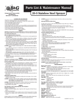
No. Part # Qty. Part Description
1 212-025 1 BOLT 5/16-18 x .75
2 214-002 18 CABLE TIE BLACK 7"
3 259-018 1 LOOM CLAMP .75" od
4 302-749 1
MANI ASSY 0807 SDA 2SA CLSD INTG DTR 12V WP6400-4PT6801-8ORFD
5 319-639 1
HRN ASSY 15CON 18GA OTR 12P(12) DTR 3P(3)-14DTP 2P(2) 30'
PARTS LIST
No. Part # Qty. Part Description
1 210-017 2 FTG 6801-8-8/E-MJ-MO
2 210-038 2 FTG 6408-HHP-8/HOLL HEX PLUG MO
3 210-113 4 FTG 6400-4-6/S-MJ-MO
4 210-127 2 FTG 6408-HHP-6/HOLL HEX PLUG MO
5 210-181 8 FTG 6400-4-6 R.031S-MJ-MO
6 232-050 2 DECL S/N (SILVER)
7 232-058 1 DECAL FASSE BLK/GOLD 1" X .75" RND CRNR
8 253-046 12 COIL HYDAC 0312600 DL DSTCH RECPT.
9 253-593 2 COIL H/F 4304112E-10 INTG DEUT DTR 12V ZENER DIODE
10 270-011 1 BLOCK M14259-1 7 CIR
11 273-008 1 CART SV10-40-0-N-00
12 273-012 1 CART CP10-20
13 273-017 1 CART SV10-21-0-N-00
14 273-058 1 CART H/F RV10-22A-0-N-NC-35-30
15 273-077 12 CART HYDAC WS 08W-01-C-N-0
PARTS LIST

Page 6 6000 SERIES SPRAYERS OPERATION & MAINTENANCE MANUAL
SPRAYER OPERATION
Figure 5
Figure 6
Figure 7
**CAUTION**
DO NOT PULL AT ROAD SPEEDS WITH
PRODUCT IN MAIN TANK
Electrocution hazard. Keep away from power lines. To
prevent serious injury or death from electrocution:
1. Stay well away from power lines when folding or
extending wings. Electrocution can occur without
direct contact.
2. Lower wings completely before moving or trans-
porting.
BOOM OPERATION
* Mount 7-function control box in a convenient place for
easy operator access. Attach to a 12 volt power
source (supplied with convenience tractor power plug).
Route control cable through tractor cab and plug con-
nectors together and route wiring harness across hitch.
*Be sure there are no power lines next to the machine
and the sprayer is located in an open area enough to
allow the booms to swing out and fold over without hit-
ting any obstructions. The hydraulic circuit control lev-
er to the boom function circuit must be placed in posi-
tive flow position prior to operating. The boom circuit
only requires 3 gpm of hydraulic flow. Set hydraulic
flow accordingly, increasing hydraulic flow will not
speed up boom function. Only reduce sprayer pump
and tractor performance.
1. LEFT BOOM TILT POSITION:
This spring-loaded-to-neutral-center toggle switch con-
trols the left boom tilt function. Move the switch up and
hold to raise the tip of the left boom and down to lower.
Release the switch, the left boom will stop moving and
it will remain in position. Use this function to raise the
tip of the boom to clear obstructions.
2. BOOM UP/DOWN:
This spring-loaded-to-neutral-center toddle switch con-
trols the boom height cylinders. Move the switch up
and hold to raise the entire boom assembly. Move the
switch down and hold to move down. Release the
switch, the boom will stop and remain at that position.
To ensure optimal boom performance never run boom
in fully down position. Doing so eliminates boom ride
accumulator.
Note: Once tower cylinder bottoms out raise 1” for low-
est recommended sprayer height.

SHOP ONLINE @ WWW.AGSPRAY.COM Page 7
SPRAYER OPERATION CONTINUED
3. RIGHT BOOM TILT POSITION:
This spring-loaded-to-neutral-center toggle switch con-
trols the right boom tilt function. Move the switch up
and hold to raise the tip of the right boom and down to
lower. Release the switch, the right boom will stop
moving and it will remain in position. Use this function
to raise the tip of the boom to clear obstructions.
4. LEFT BOOM FOLD/EXTEND:
This spring-loaded-to-neutral-center toggle switch con-
trols the left boom position. Move the switch up and
hold to fold the left boom and down to extend. Release
the switch, the left boom will stop moving and it will re-
main at that position.
**IMPORTANT**
Extend the cylinder completely when extending the out-
er boom to eliminate outer wing vibration. To insure
the wing is locked down hold the toggle switch down for
5 seconds after the boom is fully extended.
5. LEFT OUTER BOOM SWING:
This spring-loaded-to-neutral center toddle switch con-
trols the left outer boom pivot function. Move the
switch up and hold to pivot the left outer boom in and
down to pivot out. Release the switch, the left outer
boom will stop and remain at that position.
6. RIGHT OUTER BOOM SWING:
This spring-loaded-to-neutral-center toggle switch con-
trols the right outer boom function. Move the switch up
and hold to pivot the right outer boom in and down to
extend. Release the switch, the right outer boom will
stop moving and it will remain at that position.
7. RIGHT BOOM EXTEND/FOLD:
This spring -loaded-to-neutral-center switch controls
the right boom position. Move the switch up and hold
to fold the right boom and down to extend. Release
the switch, the right boom will stop moving and it will
remain in that position.
**IMPORTANT**
Extend the cylinder completely when extending the
outer boom to eliminate outer wing vibration. To insure
the wing is locked down hold the toggle switch down
for 5 seconds after the boom is fully extended.
Figure 8
Figure 9

Page 8 6000 SERIES SPRAYERS OPERATION & MAINTENANCE MANUAL
Folding/Unfolding Procedure
UNFOLDING BOOM FOR FIELD USE
**CAUTION**
Electrocution hazard. Keep away from power lines. To
prevent serious injury or death from electrocution:
1. Stay well away from power lines when folding or
extending wings. Electrocution can occur without
direct contact.
2. Lower wings completely before moving or trans-
porting.
Note: Tractor should come to a full stop before
folding or unfolding sprayer. Make sure clear of
any obstacles overhead or around sprayer that
could come in contact with boom.
1. Before unfolding boom, remove transport using
lock pins and tower cylinder transport stop (Figure
1). Reinstall lock pins and tower stop before trans-
porting sprayer.
2. Raise tilt cylinders by pushing up on “tilt” toggle
switch to raise boom out of transport saddle.
3. Hold down on outer fold switches to fold-over outer
wings to spray position. Note: Extend the cylinder
completely when extending the outer boom to elimi-
nate outer wing vibration. To ensure the wing is
locked down hold the toggle switch down for 5 sec-
onds after the boom is fully extended. (Figure 9)
4. Hold down on “main lift” boom switch to lower
boom to desired spray height. To ensure optimal
boom performance never run boom in fully down
position. Doing so eliminates boom ride accumula-
tor.
5. Reverse the above procedure when converting
from field to transport configuration.
IMPORTANT: Once tower cylinder bottoms out
raise 1”.
WARNING: Outer fold Booms are a vertical fold
and once wing goes past 90° if Air is present in
hydraulic system the wing could gravity free fall
causing possible personal or boom damage.
The sprayers are hydraulically charged at the factory,
but the following procedure should be followed on an
annual basis to prevent possible boom drop, from
transport position, raise “tilt” wings out of transport
saddle, swing the “inner” fold booms 45° out from
sprayer frame. Raise “outer” fold wings 80° from inner
wing, lower “outer” fold wings to saddle transport posi-
tion. Repeat 3 times. This cycles the hydraulic lines to
prevent air pockets in the hydraulic system to prevent
“boom drop”.
Figure 10

SHOP ONLINE @ WWW.AGSPRAY.COM Page 9
PLUMBING OPERATION
1. 1. Connect supply hose to quick fill valve (valve
3) (If top filling, open lid and insert supply hose.)
“WARNING!” Be careful if crawling on sprayer.
Steel surfaces can become slick when wet. Also
watch head while climbing onto sprayer if in
transport position. Operator must go under boom
to access platform.
2. Make sure main tank valve (valve 1) is open.
NOTE: Make sure rinse tank valve (valve 10) is
closed before filling. Rinse tank could over run and
become chemically contaminated otherwise.
3. Open supply valves and quick fill valve (valve 3)
and start filling sprayer.
4. Start sprayer pump and begin circulating solution.
(NOTE: make sure sprayer booms are off) Make
sure Agitation/Rinse valve is turned with Arrow
pointing downward for agitation and agitation
valves (valve 11 and valve 12) are open.
5. Make sure manual pressure gauge located on
sprayer hand rail has a minimum of 40 PSI and
not to exceed maximum of 85 PSI while filling.
6. With a minimum of 1/2 tank of solution begin to
add chemical.
OPTIONAL INDUCTOR:
Pull transport pin, release Safety latch and gently low-
er to bottom position. Open Inductor activation valve
(valve 8) to start venturi vacuum. Add pre-determined
chemical amount to inductor tank and then open in-
ductor tank valve (valve 9) to allow chemical to be
pulled into sprayer. (for dry or heavy viscosity products
once premeasured, add some solution by opening
inductor rinse valve (valve 7) 1/8 turn or as needed to
make into a slurry for more efficient induction.) Once
chemical has been drawn out open inductor rinse
valve (valve 7) 1/4 turn or as needed to rinse chemical
residue down for 1 minute or as needed. Close induc-
tor rinse valve (valve 7) once tank is empty close in-
ductor tank valve (valve 9). Repeat above until all
chemical is added. When done adding all chemical for
spray solution close inductor activation valve (valve 8)
and raise inductor tank to transport position, activate
safety latch, insert transport pin.
Components:
1. Main Tank Valve
2. Drain Valve
3. Quick Fill Valve
4. Agitation/Rinse Valve
5. Gate Valve
6. Inductor Rinse Valve
7. Inductor Activation Valve
8. Inductor Tank Valve
9. Rinse Tank Valve
10. Front Agitation Valve
11. Rear Agitation Valve
12. Safety Wash Valve
13. Rinse Filter
14. Main Filter
Figure 11

Page 10 6000 SERIES SPRAYERS OPERATION & MAINTENANCE MANUAL
PLUMBING OPERATION CONTINUED
NOTE: For inducting dry flowable products, adjust
PWM valve (Pulse width modulation) to 60 P.S.I.
minimum.
NOTE: Graduation marking on inductor tank are
not calibrated. Do Not Use for measuring chemical.
Only to be used as a reference point.
NOTE: Make sure inductor rinse tank valve (valve
7) is closed at all times other than when adding
chemical.
7. All chemical needs to be added before solution
level reaches 3/4 of desired capacity.
NOTE: Follow all chemical manufacture label in-
structions.
8. When solution reaches desired tank level, close
quick fill valve (valve 3) and/or stop solution from
being added to sprayer. Disconnect supply hoses,
secure all sprayer covers.
9. Continue to run sprayer pump to circulate sprayer
solution.
10. Fill auxiliary tanks as needed.
- Rinse
- Safety wash
- Foam Marker
11. Allow solution to circulate for several minutes be-
fore applying.
Figure 12
Sprayer Controls (Figure 12)
a. Sprayer Controls Rinse
b. Sprayer Controls Agitation
c. Sprayer Controls Rinse Tank
d. Sprayer Controls Main Tank
e. Clean Water Hand Rinse Tank
f. Main Tank Fill Valve (2” Quick Fill)
g. Rinse Tank Fill Valve (2” Quick Fill)
h. Main Tank Shut Off Safety Valve (Under Tank. Not Pictured)
G F E
D C
B A

SHOP ONLINE @ WWW.AGSPRAY.COM Page 11
TANK RINSE OPERATION
Fresh water rinse tank located behind the main tank is
designed to allow the operator to rinse the sprayer
without having to leave the field.
1. Make sure sprayer pump is off.
2. Turn spray control valve from Spray Tank to Rinse
Tank. (valve 1)
3. Turn spray control valve from Agitation to Rinse
Tank (valve 10)
4. Turn pump on make sure boom valves are off.
Manual pressure gauge on front of the sprayer
needs to read between 50 and 75 PSI (see sprayer
controls for adjustment procedure)
5. After allowing sufficient time for agitation lines to
rinse then turn agitation/rinse valve (valve 4) 1/2
turn so arrow points upward to activate rinse balls.
6. Run pump until rinse tank is empty.
7. Shut pump off.
8. Turn spray control valve from Rinse Tank to Spray
Tank (valve 10)
9. Turn spray control valve from Rinse Tank to Agita-
tion (valve 1)
10. Turn agitation/rinse valve (valve 4) 1/4 turn so
arrow points horizontal and both lines are off.
11. Lightly spray rinse solution over pre-sprayed area.
12. Shut off pump and booms when tank is empty.
13. Repeat as needed when changing chemicals.
NOTE: Recommendation that a chemical neutral-
izer be run threw the rinse system between differ-
ent chemical usages. Follow procedures stated
above. Rinse with water following chemical neu-
tralizer before adding chemical.
OPTIONAL: Rinse Boom plumbing while chemical still
in tank.
1a. Close agitation/rinse valve (valve 4) to horizontal
position (shutting off both lines).
2a. Start sprayer pump, open boom valves and
dispense lightly over pre-sprayed area.
3a. Run until adequately rinsed.
SPRAY CONTROLLER OPERATION
1. See spray controller manufactures manual for
proper installation and setup.
2. Once controller is installed according to manufac-
tures recommendations test the system with
water.
3. Add a couple hundred gallons of water unfold
boom in a safe area according to folding/unfolding
procedures.
4. Engage pump per pump operation.
5. Turn master boom switch to the on position.
6. Turn individual boom switches on one at a time
cycling on and off to make sure each is operating
properly.
7. With master switch on and all individual boom
switches on, cycle pressure up and down (in
manual mode if using an automatic rate controller)
to determine spraying pressure range.
8. Repeat #7 with master switch on and individual
booms off. This may be required to be done to
attain recommended PSI for proper operation of
optional inductor tank and rinse system.

Page 12 6000 SERIES SPRAYERS OPERATION & MAINTENANCE MANUAL
SPRAYER START-UP PROCEDURE
1. Start with water (fill tank).
2. Make sure hydraulic lines are in correct port.
3. PWM valve has a cap on top. Remove cap and
screw set screw all the way down to put pump in
manual mode.
4. Make sure pump is primed. Pump is primed by
opening different strainer bowls and let water flow
out. Reassemble strainer bowl.
5. Make sure the proper valves are open on control
panel. The large handle pointed in spray position
and the small valve says “rise tank and agitation” is
pointed to agitation.
6. Go to monitor, with controller in manual, booms off
and master switch on. Press and hold the increase
for 10 seconds or pressure starts to rise.
NOTE: If pressure does not rise, the pump is prob-
ably not primed correctly. Recheck the valves are
open.
7. Once the system is spraying correctly in manual
mode, shut system down.
8. Go to PWM valve on pump, remove cap and turn
set screw all the way to up position and replace
cap.
9. Return to monitor and set to Rate 1 or auto, with
booms on and master off (if using a Raven 440 or
450). Enter a self test speed by hitting self test,
enter, the speed you wish to travel and enter again.
10. Start pump.
11. Turn master on. You should be hitting your desired
rate. If not, redo steps 6 - 11.
12. You should be ready to spray.
NOTE: Remember the Raven 440 and 450 have a
feature called “zero speed shutoff” which means if
tractor is not moving in rate 1 or 2 and the master
switch gets turned on, you will lock the monitor up.
If this happens, reenter self-test speed and test
again. Make sure you are moving before master
switch is turned on, in automatic mode.
Initial Start-Up
1. Follow label instructions for proper mixing of foam
concentrate. Fill tank with desired amount of water
and then add foam according to label. It is better to
have more foam concentrate added to the water
than less, because liquid flow amount can be
regulated by Wet/Dry knob.
NOTE: Start with control knob at center position.
2. To start foamer: turn main power switch to on
position then switch the toggle switch to the left or
right position. Foam will travel from the control
valve (144f-1-3) toward the right or left side of the
boom. Reverse the L/R toggle switch and foam will
travel the opposite direction. (Figure 13)
NOTE: If liquid pump does not prime on start up,
run Wet/Dry control at full wet until prime.

SHOP ONLINE @ WWW.AGSPRAY.COM Page 13
TROUBLE SHOOTING
Figure 13
1. If foam is soupy, set more to dry on foamer control
or more foam concentrate needs to be added to the
water (concentrates for pressurized tank systems
are not recommended for use with SI foam
markers)
2. Water conditions (soft or hard) will also vary
foaming action Your local coop will probably be
able to advise which foam concentrate works best
with local water conditions.
3. If a change of drop rate is desired: adjust knob
more toward wet until desired rate is achieved.
4. Drops are too far apart or you are doing post
emerge work and can not see drops do to plant
height: Remove rubber boot from end of drop hose
to get a nearly straight stream of foam at end of
boom.
NOTE: If you are having trouble seeing foam try
either Tracer Pink (hot pink) or Tracer Blue
colorants from Ag Spray Equipment.

Page 14 6000 SERIES SPRAYERS OPERATION & MAINTENANCE MANUAL
440/450 RAVEN CONTROLLER WITH PWM SETUP
1. Install Raven 440 or 450 control console and hook up to sprayer (see instructions inside controller box).
2. Turn on control console.
When making selections/entering numbers, always be sure to press enter to save your settings.
3. Make the following selections when prompted:
- Units US (Enter)
- Speed sensor 2 “SP2” (Enter)
- Valve type C-P “Closed PWM” (Enter)
4. Select Boom Cal “Raven 440, 1-3”, “Raven 450, 1-5”
- Enter number of inches covered for each section (not full width of boom).
To find the number of inches covered, multiply the number of nozzles per section and the number of inches between
nozzles. (Ex. Section one; 12 nozzles x 20 inch between nozzles =240 inches)
5. Select Speed Cal
- Enter 783 (This is the cal number for a Garmin GPS Sensor).
6. Select Meter Cal-Enter the meter cal number which is printed on the tag for on your Flow Meter. (ex. 720)
7. Select Valve Cal
- Enter 43 (This is only for use with the PWM controlled hydraulic pump).
8. Select Rate 1
- Enter the number of gallons/acre you want to spray in Rate 1. (ex. 10.0)
9. Select Rate 2-Enter the number of gallons/acre you want to spray in Rate 2. (ex. 20.0)
10. Select DATA MENU
- Scroll to PWM Frequency and enter 110.
11. Hold SELF TEST
- This will scroll through all settings to make sure everything is entered.
- If all cal numbers are entered, it will stop scrolling after a few seconds. (move to step 12.)
- If any cal numbers have not yet been entered, it will keep scrolling. (If so, you will need to go
back through your cal numbers and make sure they are all entered correctly.)
12. Turn the Flow Control to MAN for manual control, turn the Booms all to the off position and turn the master on.
13. Hold INC to build pressure. This will allow you to check any leaks and use your inductor tank (if applicable) while
sitting. BE AWARE NOT TO OVER PRESSURIZE SYSTEM
14. TO SPRAY
- Turn the Flow Control to Rate 1 or Rate 2 (preference).
- The speed you need to travel is dependent on the rate at which you are spraying.

SHOP ONLINE @ WWW.AGSPRAY.COM Page 15
2630 JD RATE CONTROLLER WITH PWM SETUP
1. After hooking up all wiring between tractor and sprayer, turn the system on.
2. Make sure all nozzles are open with desired tips installed.
3. From the Menu, select Rate Controller
4. Setup your Implement type
- Select Pull Behind Sprayer, enter a name and tank size.
5. Select the Setup Tab (right)
6. Select the Implement Tab (top)
- Enter your boom width
- Adjust the width of each section
- Be sure to enter any Fence Row(s) if applicable
7. Select the System Tab (top)
- Section Valve type – 3 wire
- Constant Flow – no
- Control Valve Type – PWM
8. Select PWM Setup
- Control Valve Calibration – 2743
- Coil Frequency – 110
- High Limit – 100
- Low Limit – 1
9. Select Calibrate PWM
- Turn Master ON and press Start
- Decrease if necessary to make sure Low limit is at or around 1 gal/min. Set Low Limit
- Increase if necessary to make sure High limit is at or just below max pump rotation or 80 psi.
Set High Limit and turn off Master.
- If you return to PWM Setup it may show new numbers in the High Limit and Low Limit.
10. Setup your Flowmeter
- Flowmeter Calibration – Enter the Flowmeter cal. number located on your flow meter.
- Flowmeter Units – 10 Gal.
11. Select the Rates Tab (top)
- Set your rates at gal/acre.
12. Select the Diagnostics Tab (right)
- From the dropdown menu under the Tests tab, select Nozzle Flow Check
- Enter your desired speed into the Test Speed
- Enter your desired Gal/Acre into the Rate
- Turn the Master on and press Start to test
(At this point you can see the system will adjust its self to run at the desired speed while you are
not driving.)

Page 16 6000 SERIES SPRAYERS OPERATION & MAINTENANCE MANUAL
OPTIONAL SPRAY
CONTROLLER SPEED SENSOR
Figure 14
If equipped with an automatic rate controller, a speed
sensor is sent along in the controller kit. The sensor
needs to be mounted to the cap or sprayer with a clear
line of sight to the sky. The red wire will need to be
hooked up to 12 volt power. See rate controller opera-
tion manual for specific calibration numbers (Figure
14).
Raise the ladder into the vertical position and push
over and down to secure in the locked position. The
lock is part of the ladder anchor bracket. Position the
ladder in the up and locked position whenever the
sprayer will be moved (Figure 15).
Figure 15
LADDERS
SERVICE & MAINTENANCE
1 Review the Operator’s Manual and all safety items
before working with, maintaining or operating the
sprayer.
2. Place all controls in neutral, stop the tractor engine,
turn monitor off, set park brake, remove ignition
key, wait for nozzles to stop spraying before
servicing, adjusting, repairing or unplugging.
3. Follow good shop practices:
- Keep service area clean and dry
- Be sure electrical outlets and tools are properly
grounded
- Use adequate light for the job at hand.
4. Before applying pressure to a hydraulic system,
make sure all components are tight and that steel
lines, hoses and coupling are in good condition.
5. Before applying pressure to chemical system,
make sure that all connection are tight and that all
hoses and fittings are in good condition.
6. Relieve pressure from hydraulic circuit before
servicing or disconnecting from tractor.
7. Keep hands, feet, clothing and hair away from all
moving and/or rotating parts.
8. Clear the area of bystanders, especially children,
when carrying out any maintenance and repairs or
making any adjustments or filling.
9. Place stands or blocks under the frame before
working beneath the machine.
10. Wear safety goggles, neoprene gloves and
protective clothing when working on the sprayer
filled with active chemical.
11. Wash machine to remove all chemical residue
before working on unit. Wear appropriate
protective gear at all times.
12. Protect yourself from chemical contamination.

SHOP ONLINE @ WWW.AGSPRAY.COM Page 17
BREAK-IN
Although there are no operational restrictions on the
sprayer when used for the first time, it is recommended
that the following mechanical items be checked:
A. After operating for 1/2 hour
1. Re-torque all the wheel bolts.
2. Re-torque all other fasteners and hardware.
3. Check that all electrical connections are tight.
4. Check that no chemical or hydraulic lines are
being pinched or crimped. Re-align as required.
5. Check that all nozzles are working properly.
Clean or replace as required.
6. Lubricate all grease fittings. (Figure 17 & 18)
B. After 5 hours and 10 hours of operation
1. Re-torque all wheel bolts, fasteners and
hardware.
2. Check chemical and hydraulic line routing.
3. Check that all nozzles are working properly.
4. Then go to the normal servicing and
maintenance schedule as defined in the
Maintenance Section.
1. When unit is stored during freezing temperatures,
drain unused foam solution from tank (disconnect
air pump and run liquid pump until unit is near
empty), fill tank with enough foam marker anti-
freeze to cover bottom of suction hose. Then run
unit until antifreeze is going into pvc mixing
chambers.
1. Route the 20’ split harness and control box to the
operator’s desired location. **Make sure the cable
does not contact any hot, sharp or moving objects
to avoid shorts and breaks**
2 Connect the red and white wires directly to the
battery. DO NOT CONNECT the power wires
through any fuse or switch boxes on the tractor,
this will cut down on amps to the marker
(Figure 16).
* On units with 12 volt batteries, contact the red lead
to the positive post and the white lead to the
negative post.
** On units with two 6 volt batteries, connect the red
lead to the positive post that feeds the starter and
the white lead to opposite battery ground.
FOAM MARKER
WINTER STORAGE
OPTIONAL FOAM
MARKER OPERATION
Figure 16

Page 18 6000 SERIES SPRAYERS OPERATION & MAINTENANCE MANUAL
GREASING
Figure 17
Figure 18
Figure 19
1. Wipe grease fitting with a clean cloth before greasing
to prevent injecting dirt and frit into joint.
2. Replace and repair broken fittings immediately.
3. If a fitting will not take grease, remove and clean
thoroughly. Also clean lubricant passageway.
Replace fitting if necessary.
*Note: Grease 18 points 8 hours or daily.
Apply adequate grease to the following:
1. L/R Breakaway Hinge
2. L/R Outer Boom Hinge
3. L/R Inner Boom Hinge
L/R GREASE LOCATIONS
4. L/R Center Section Bushing (Lower)
5. L/R Center Section Bushing (Upper)
6. Parallel Hinge Bushings (Total of 8) (4 Top Pins & 4 Bottom Pins)
Controller
Wiring
Diagram
12 V+ Ground Section 5 Section 4 Section 3 Section 2 Section 1
Red Black Gray Yellow Green Brown White TeeJet 844 & 854
Red Black - - Orange Yellow Green TeeJet 734 & 744
Red White - - Blue Brown Black Raven 330 & 440
Red White Wht/Brwn Black/Wht Blue Brown Black Raven 440 & 450
5 5
5
5

SHOP ONLINE @ WWW.AGSPRAY.COM Page 19
SPRAY CONTROL VALVE WIRING
1. The motorized ball valves equipped on the sprayer
require 12V
+
constant power and ground to make
actuate. When 12V
+
is sent from the controller thru
the signal wire per each section the valve will open as
long 12V
+
is present to the section wire. Once power
is removed by turning off the individual or master
switch, the valves will close.
The fluid in the sprayer is continually being filtered
through a screen filter. The sprayer must have clean
water to prevent clogging of the screens and check
valves when in use. These screens must be cleaned
daily or more often as required. To clean, follow this
procedure:
1. At the start of each day before the water and
chemicals are added, the screens should be
checked and cleaned.
2. If there is water or solution in the sprayer, close
valve 1 and valve 4 (Figure 21) to isolate the
screens.
3. Loosen the filter bodies by hand. Do not use a
wrench as this could damage the filter body.
4. Remove the screens and inspect them for foreign
material.
5. Clean them using clean water.
FILTER CLEANING
Figure 20
2. Each motorized ball red wire connects to the 12V
+
terminal. Each motorized ball valve black wire will
connect to ground terminal, and each motorized
ball valve white wire will connect to the
corresponding section terminal.
6. Inspect for holes or tears. If there is damage,
replace.
7. Install the screens and body to the filter heads and
tighten by hand. Do not use a wrench as this
might damage the body. Do not overtighten and
crack the head.
8. Open valves 1 & 4 to allow the solution to circulate.
9. Drain all screens before storage to avoid freezing.
Figure 21

Page 20 6000 SERIES SPRAYERS OPERATION & MAINTENANCE MANUAL
SUGGESTED WINTERIZING PROCEDURE
1. Drain all fluids from sprayer strainers, nozzles, etc.
2. Pour approximately 15 gallons of RV antifreeze in
rinse tank
Note: Do not forget to pour 1 gallon into main
tank and inductor.
3. Repeat steps 3-7 on start up procedure with the
exception of pulling antifreeze from rinse tank in-
stead of main tank.
4. Make sure to turn on valve that is coming off of flow
back ball valves. This valve should be in the On po-
sition when winterizing to clean out on/off valves.
5. Once you have sprayed RV antifreeze through all
nozzles, drain all water and antifreeze out.
6. It is always a good idea to take apart manifold
clamps to drain water and antifreeze out.
WINTERIZING CHECK LIST
Flowback Valves Inductor
Pump Rinse Tank
Rinse Balls Feed Lines & Nozzles
Hand Wash Tank
REMOVING FROM STORAGE
When removing from storage and preparing to use,
follow this procedure.
1. Clear the area of bystanders, especially small
children, and remove foreign objects from the
machine and the working area.
2. Check
a. Tank for cracks
b. Tank hold down hardware
c. All hardware. Tighten as required.
d. Tire pressure.
e. All sprayer and hydraulic lines, fittings and
connections. Tighten as required.
3. Lubricate all grease fittings.
4. Replace any defective parts.
5. Fill the tank with 20 gallons (75 liters) of clean
water and run for 5 minutes in the wash cycle.
Open and close all valves several times. Flush
water through the booms.
6. Repeat step 5.
7. Calibrate the pump, nozzles and sprayer before
using.
8. Go through the pre-field checklist before using.
/