Page is loading ...

Owner's Manual
I;RRFTSMRN°
1.5 HP (Max. Developed)
1/2" and 1/4" Router Collet
112" Removable Shaper Spindle
BENCH TOP
SHAPER/ROUTER
Model No.
137.217100
CAUTION:
Before using this shaper/router,
read this manual and follow
all its Safety Rules and
Operating Instructions.
• Safety Instructions
• Installation
• Operation
• Maintenance
• Parts List
• Espa_ol
Customer Help Line
1-800-843-1682
Sears, Roebuck and Co., Hoffman Estates, IL 60179 USA
Part No. 137217100001

SECTION
Warranty ........................................
Product Specifications ...........................
Safety Instructions ..........
Accessories and Attachments.
Carton Contents ............
Know Your Shaper / Router .o
Assembly and Adjustments.
Operation ...............
Maintenance .............
Troubleshooting guide .....
Parts ...................
Espa_ol .................
PAGE
'MOTOR ................... 120 V, 60 HZ, 9 AMP AC
DOUBLE INSULATED ....... Yes
HORSEPOWER ............ 1.5 HP (Max. Developed)
SPINDLE
SPEED ............... 10,000 R.RM. (No Load)
DIAMETER ............ 1/2'
HEIGHT ADJUSTMENT .. 7/8'
ROTATION ............. Reversible
CUTTER CAPACITY ......... 2"
ROUTER COLLET .......... 1/2", 1/4"
TABLE SIZE ............... 18' X 15-7/16"
TABLE INSERT ............. Reversible
FENCE ................... Yes
MITER GAUGE ............. Yes
DUST CHUTE .............. Yes
WEIGHT .................. 35.5 Ib
To avoid electrical hazards, fire hazards, or damage to
the tool, use proper circuit protection. Use a separate
electrical circuit for your tools.
Your shaper/router is wired at the factory for 120V
operation, Connect to a 120V, 15 AMP branch circuit and
use a 15 AMP time delay fuse or circuit breaker. To avoid
shock or fire, replace power cord immediately if it is worn.
cut or damaged in any way.
Some dust created by power sanding, sawing, grinding, drilling, and other construction activities
contains chemicals known [to the State of California] to cause cancer, birth defects or other
reproductive harm. Some examples of these chemicals are:
Lead from lead-based paints.
• Crystalline silica from bricks,cement and other masonry products.
• Arsenic and chromium from chemically-treated lumber.
Your risk from these exposures varies, depending on how often you do this type of work. To reduce
your exposure to these chemicals:work in a well ventilated area, and work with approved safety
equipment, such as those dust masks that are specially designed to filter out micros-copic particles.

GENERAL SAFETY INSTRUCTIONS
BEFORE USINGTHE SHAPER/ROUTER
Safety is a combination of common sense, staying alert
and knowing how to use your shaper/router.
To avoid mistakes that could cause serious injury, do not
plug the shaper/router in until you have read and
understood the following:
1. READ and become familiar with this entire instruction
manual. LEARN the tools applications, limitations, and
possible hazards.
2. KEEP GUARDS IN PLACE and in working order.
3.. REMOVE ADJUSTING KEYS AND WRENCHES.
Form the habit of checking to see that keys and
adjusting wrenches are removed from the tool before
turning ON.
4 KEEP WORK AREA CLEAN. Cluttered areas and
benches invite accidents.
5.
6°
DON'T USE IN A DANGEROUS ENVIRONMENT.
Don't use power tools in damp or wet locations or
expose them to rain. Keep work area well lighted.
KEEP CHILDREN AWAY. All visitors should be kept at
a safe distance from the work area.
7. MAKE WORKSHOP KID PROOF with padlocks, master
switches, or by removing starter keys.
8. DON'T FORCE THE TOOL. It will do the job better
and safer at the rate for which it was designed.
9 USE THE RIGHT TOOL. Don't force tool or the
attachment to do a job for which it was not designed.
10. USE PROPER EXTENSION CORD. Make sure your
extension cord is in good condition. When using an
extension cord, be sure to use one heavy enough to
carry the current your product will draw. An undersized
cord will result in a drop in line voltage and loss of
power which will cause the tool to overheat. The table
on page 5 shows the correct size to use depending on
cord length and nameplate ampere rating. If in doubt,
use the next heavier gauge. The smaller the gauge
number, the heavier the cord.
11 WEAR PROPER APPAREL. DO NOT wear loose
clothing, gloves, neckties, rings, bracelets, or other
jewelry which may get caught in moving parts.
Nonslip footwear is recommended. Wear protective
hair covering to contain long hair.
12,
13.
14.
15.
16.
17.
18.
IF WEAR YOUR _ ALWAYSWEAR EYE
/-_ _ _l_.!_i', PROTECTION.
'_OGGLE,/jr Any shaper/router can throw
_'__,_, -..._j_- foreign objects into the eyes
i_ ', _"-"_L._ _- which could cause permanent
VL,LL _,<,:_ ,M,'_-g_3;£7 eye damage. ALWAYS wear
Safety Goggles (not glasses)
that comply with ANSI safety standard Z87.1.
Everyday eyeglasses have only impact-resistant
lenses. They ARE NOT safety glasses. Safety Goggles
are available at Sears. NOTE: Glasses or goggles not
in compliance with ANSI Z87.1 could seriously hud
you when they break.
WEAR A FACE MASK OR DUST MASK.
Shaping operation produces dust.
SECURE WORK. Use clamps or a vise to hold work
when practical. It's safer than using your hand and it
frees both hands to operate too!.
DISCONNECTTOOLS before servicing and when
changing accessories, such as blades, bits, cutters,
and the like.
REDUCETHE RISK OF UNINTENTIONAL STARTING.
Make sure the switch is in OFF position before
plugging in.
USE RECOMMENDED ACCESSORIES. Consult the
owner's manual for the recommended accessories.
The use of improper accessories may cause risk of
injury to persons.
NEVER STAND ON TOOL. Serious injury could occur
if the tool is tipped or if the cutting tool is unintentionally
contacted.
19. CHECK FOR DAMAGED PARTS. Before further use of
the tool. a guard or other part that is damaged should
be carefully checked to determine that it will operate
properly and perform its intended function. Check for
alignment of moving parts, binding of moving parts.
breakage of parts, mounting, and any other conditions
that may affect its operation. A guard or other part that
is damaged should be properly repaired or replaced.
20° NEVER LEAVETOOL RUNNING UNATTENDED.
TURN THE POWER OFF. Don't leave the tool until
it comes to a complete stop.
21.
22.
23.
DON'T OVERREACH. Keep proper footing and
balance at all times.
MAINTAIN TOOLS WITH CARE. Keep tools sharp
and clean for best and safest performance. Follow
instructions for lubricating and changing accessories.
DIRECTION OF FEED. Feed work into a blade or cutter
against the direction of the rotation of the blade or
cutter only.
SAVE THESE INSTRUCTIONS

24. DO NOT operate the tool if you are under the influence
of any drugs, alcohol or medication that could affect
your ability to use the tool properly.
25.
Dust generated from certain materials can be
hazardous to your health. Always operate the
shaper/router in a well-ventilated area and
provide for proper dust removal. Use dust collection
systems whenever possible.
SPECIFIC SAFETY INSTRUCTIONS
FOR THE SHAPER/ROUTER
[1_11,5,/"_t,t_11_[_€
Do not operate your shaper / router until it is completely
assembled and installed according to the instructions.
1. IF YOU ARE NOT thoroughly familiar with the operation
of shaper/reuters, obtain advice from your supervisor,
instructor, or other qualified person.
2. MAKE SURE wiring codes and recommended
electrical connections are followed and that the
machine is properly grounded.
3. NEVER turn the shaper/router ON until all tools,
scraps of wood, and other debris are removed from
the table.
4. DO NOT shape or rout materials less than 12" in
length or 4" in width without special supporting fixtures.
Use a holding jig or fixture to guide it past the cutter.
5. ALWAYS use a miter gauge when edge-shaping a
workpiece less than 6" wide. Keep your hands at least
6" away from the cutting tool.
6. AVOID awkward hand positions. A sudden slip could
allow your hand to contact the cutter.
7. USE A PUSH STICK or a scrap piece of work material
to push the workpiece, to keep your hands safely away
from the cutter.
8.
10.
11.
12.
13.
t4.
15.
NEVER run the workpiece between the cutter and
the fence backstop.
USE AUXILIARY GUIDES clamped to the fence or
table, if necessary, to keep your hands safely away
from the cutter.
DO NOT feed material that is warped, contains knots,
or is embedded with foreign objects, such as nails or
staples.
NEVER start the shaper / router with the workpiece
in contact with the cutter,
ALWAYS use the cutter safety guard provided with
the machine.
NEVER perform layouL assembly, or set-up work on
the table while the shaper is operating.
KEEP the cutting tools sharp and free from rust and
pitch.
16. ALWAYS ADJUST the fence as close as possible to
the cutter, keeping the cutterbetween thefence boards.
17. ALWAYS lock the fence hardware securely after
making fence adjustments.
18. MAKE CERTAIN the cutting tools are propedy installed
and secured before starting the machine.
19. MAKE SURE the shaper/router is mounted to a
secure surface. Check carefully for any tipping or
"walking", and secure the workbench or supporting
surface before using the tool.
20.
21.
22.
23.
24.
MAKE SURE THE KEYED WASHER is installed directly
under the SPINDLE JAM NUT and the nut is tight.
Serious injury may result if the nut loosens.
ALWAYS LOCK the cutter depth lock handle after
adjusting it.
ALWAYS use a collar or bearing guide if cutting with
the fence assembly removed.
DO NOT perform any operation freehand. ALWAYS:
• USE THE FENCE for straight shaping.
• USE THE MITER GAUGE for end shaping.
• USETHE STARTING PIN AND COLLARS for
curve shaping.
ALWAYS feed the workpiece AGAINST the cutter
rotation.
25, WHEN SHAPING with collars and the starting pin:
• THE COLLAR MUST have sufficient bearing surface
for contacting the workpiece.
• THE WORKPIECE MUST be fairly wide in proportion
to the cut being made. NEVER shape short
workpieces of narrow material.
• THE CU-I-rER SHOULD be positioned below the
collar whenever possible.
26. MAKE all adjustments with the power OFF.
27. WEAR EAR PROTECTION when operating this tool.
28. AVOID deep cuts. Excessive depth of cut can cause
kick-back.
ELECTRICAL REQUIREMENTS
POWER SUPPLY AND MOTOR
SPECIFICATIONS
The AC motor used in this saw is a universal, nonreversible
type. See "MOTOR" in the PRODUCT SPECIFICATIONS
section on page 2.
To avoid electrical hazards, fire hazards, or damage to the
tool, use proper circuit protection. Your saw is wired at the
factory for 120V operation. Connect to a 120V. 15 Amp
circuit and use a 15 Amp time delay fuse or circuit breaker.
To avoid shock or fire, if power cord is worn or cut, or
damaged in any way, have it replaced immediately.
SAVE THESE INSTRUCTIONS

DOUBLE INSULATED
The shaper / router is double insulated to provide a double
thickness of insulation between you and the tool's electrical
system. All exposed metal parts are isolated from the
internal metal motor components with protecting insulation.
Replacement parts - When servicing use only identical
replacement parts.
Polarized piugs- This shaper/router has a plug that
[ooks like the one shown below:
To reduce the risk of electrical shock, this shaper/router
has a polarized plug (one blade is wider than the other).
This plug will ffi in a polarized receptacle only one way. If
the plug does not fit fully in the receptacle, reverse the plug.
If it still does net f"rt,contact a qualified electrician to install
the proper receptacle. Do not change the plug in any way.
Double insulation does not take the place of normal safety
precautions when operating this tool.
To avoid electrocution:
1. Use only identical replacement parts when servicing
a Iool with double insulation. Servicing should be
performed by a qualified lechnician.
2. Do not use power tools in wet or damp areas or
expose them to rain. This tool is intended for indoor
use only.
MOTOR SAFETY PROTECTION
IMPORTANT: To avoid motor damage, this motor
should be blown out or vacuumed frequently to keep
sawdust from interfering with normal motor ventilation.
1. Connect this tool to a 120V, 15 Amp branch circuit
with a 15 Amp time delay fuse or circuit breaker.
Using the wrong size fuse can damage the motor.
,
3.
4.
If the motor won't start, turn the switch OFF
immediately. UNPLUG THE TOOL. Check the spindle
shaft to make sure it turns freely. If the spindle is free,
try to start the motor again. If the motor still does not
start, contact the Sears Service Center.
If the motor suddenly stalls while shaping wood.
turn the switch OFF, unplug the tool. and free
the cutter from the wood. The shaper may now be
restarted and the cut finished.
Fuses may "blow" or circuit breakers may trip
frequently if:
5.
a. Motor is overloaded. Overloading can occur if
you feed too rapidly or make too many start /
stops in a short time.
b. Line voltage is more than 10% above or
below the nameplate voltage. For heavy loads,
however, the voltage at motor terminals must
equal the voltage specified on the nameplate.
c. I nproper or dull cutters are used.
Most motor troubles may be traced to loose or
incorrect connections, overload, low voltage (such as
small size wire in the supply circuit) or to overly long
supply circuit wire. Always check the connections, the
load and the supply circuit if the motor doesn't work
well. Check wire sizes and length with the Extension
Cord Chart below.
GUIDELINES FOR EXTENSION CORDS
USE PROPER EXTENSION CORD. Make sure your
extension cord is in good condition. When using an
extension cord, be sure to use one heavy enough to carry
the current your product will draw. An undersized cord will
result in a drop in line voltage, and loss of power which
will cause the tool to overheat. The table below shows the
correct size to use depending on cord length and nameplate
ampere rating. If in doubt, use the next heavier gauge.
The smaller the gauge number, the heavier the cord.
Be sure your extension cord fs properly wired and in
good condition.Always replace a damaged extension cord
or have it repaired by a qualified person before using it.
Protect your extension cords from sharp objects,
excessive heat and damp or wet areas.
Use a separate electrical circuit for your tools. This
circuit must not be less than #12 wire and should be
protected with a 15 Amp time lag fuse. Before connecting
the motor to the power line, make sure the switch is in
the OFF position and the electric current is rated the
same as the current stamped on the motor nameplate
Running at a lower voltage will damage the motor.
(when using 120 volts only)
Ampere Rating Total length of cord in feet
merethan notmor_tha_., 25' 50' 100' 150'
0 6 18 16 16 14
6 10 18 16 14 12
10 12 t6 16 14 12
12 16 14 12 Not recommended
To avoid injury, make certain the receptacle is properly
grounded. If you are not sure have a certified electrician
check the receptacle.
This shaper / router is for indoor use only. Do not expose
to rain or use in damp locations.
SAVE THESE INSTRUCTIONS

PROHIBITED ACCESSORIES
Use only accessories recommended for this shaper/router.
Follow instructions that accompany accessories. Use of
improper accessories may cause hazards.
Do not attempt to modify this tool or create accessories
not recommended for use with this tool. Any such alteration
or modification is misuse and could result in a hazardous
condition leading to possible serious injury.
UNPACKING AND CHECKING CONTENTS
Toavoid injury from unexpected starting or electrical shock.
do not plug the power cord into a power source receptacle
during unpacking and assembly. This cord must remain
unplugged whenever you are working on the shaper/router
1. Carefully unpack the shaper/router and all its parts.
and compare against the illustration on page 7.
2. Place the tool on a secure surface and inspect
carefully.
RECOMMENDED ACCESSORIES
Visit your Sears Hardware Department or see the
Craftsman Power and Hand Tools Catalog to purchase
recommended accessories for this power tool.
To avoid the risk of personal injury, do not modify this
power tool or use accessories not recommended by Sears
If any part is missing or damaged, do not plug the
shaper/router in until the missing or damaged part is
replaced, and assembly is complete. To avoid electrical
shock, use only identical replacement parts when
servicing double insulated tools.
TABLE OF LOOSE PARTS
ITEM DESCRIPTION QUANTITY
A. Shaper/Router 1
B Miter gauge 1
C Fence backstop t
D. Wooden boards 2
E. S'iding fence bracket t
F. Guard assembly 1
G Lock knobs (2 short - 2 long) 4
H. Washers (large opening, flat) 5
t. Washers (small, flat) 2
J Hex. nuts 4
K. Screws (flat head phillips) 4
L. Dust chute 1
M. Table insert 1
N. Shaper spindle 1
O Collars 5
P Keyed washer 1
Q Hex nut 1
R Router nut (targe& small hole) 1
S Starting pin 1
T. 1/2" Collet 1
U. 1/4" Collet 1
V. Shaper nut (large & large hole) 1
W Wrenches (open end) 2

UNPACKING YOUR SHAPER / ROUTER
r" "i
@ @!'_@ @
D
G
j K
L M
N P O R S
®
T
®
u v w

Shapernut
Woodfenceboard
insert
Guardlockknob
Guardbracket
Cutterguard
Shaperspindle
Startingpin
Miter gauge
Table
Cutter depth lock handle
Spindle depth adjustment
Wrench stora(
Forward/Reverse
switch
ON/OFF switcl
Collar/cutter storage
Router nut Collars
• Warning label
Miter gauge storage
Base
Mounting hole
Fence backstop
Sliding fence bracket
Fence backstop knob
Guard height
adjustment knob
-- Dust chute
Exl_aust port
Scale
Sliding fence knob
Mounting hole
Power cord bracket Power cord
Wrenches

ASSEMBLY INSTRUCTIONS
TOOLS NEEDED
Open end wrenches(provided)
I ,I,l.l,i,l,l,l.l,t,_ll I
Combinationsquare Phillips screwdriver
For your safety, never connect the plug to the power source
receptacle until all assembly and adjustment steps are
completed, and you have read and understood the safety
and operating instructions.
INSTALLING THE FENCE ASSEMBLY (FIG. A, B, C)
The Backstop (FIG. A)
1. Place the fence backstop (1) on the table, aligned
with the two holes (2) at the rear of the table.
2. Insert a long knob (3) through a washer (4), and thread
through a slot (5) of the backstop into the table hole.
3. Repeat for the other backstop slot, and tighten the
two knobs.
Fig. A
Fig. B
The Wood Fence (FIG. C)
1. Install the two wood fence boards (9) to the fence
brackets. Place them with the beveled edge toward
the center, facing the cutter shaft, as shown.
2. Insert four phillips flat head screws (10) through the
front of the boards.
3. Place the flat washers (11) and hex nuts (12) on the
screws from the fence backstop side.
4. Loosen the fence lock knobs, adjust the fence
brackets to their most forward position. Tighten the
lock knobs.
5. Using a straightedge or combination square, align the
two wooden boards so they are even with each other.
Tighten the screws and nuts.
Fig. C
10
\
The Sliding Bracket (FIG. B)
1. Place the sliding bracket (6) on the grooved track at
the side of the backstop.
2. Thread a short knob (7), with a washer (4), through
the bracket slot (8) into the threaded hole of the
backstop. Tighten the knob.
12
9 ' ....

INSTALLING THE DUST CHUTE (FIG. E)
Place the dust chute (1) firmly into the fence backstop
port (2). A wet / dry shop vacuum hose can be attached to
the chute to help keep the work area free of wood chips.
CAUTION: Never leave a wet/dry vacuum hose connected
unless the vacuum is turned on during operation, or the
machine will clog with chips.
Fig. E
"2
TABLE INSERT (FIG. F)
The table insert must be in position when shaping a
workpiece, to provide support and to keep dust and chips
out of the spindle area.
1. When the cutter or router bit is positioned above the
table surface, install the table insert with the smaller
hole (1) up, to provide a surface flush with the table.
2. When the cutter or router bit is positioned partially
below the table surface, the insert must be installed
with the larger opening facing (2) up, to provide a
recessed surface.
CAUTION: Make sure the cutter will not hit the table
insert before turning the tool ON.
Fig. F
®
®
®
®
STARTING PIN (FIG. G)
The starting pin (1) is used to support the workpiece when
using the shaper/router without the fence and sliding
bracket. Thread the starting pin into the table hole (2)
located approximately 4" from the spindle shaft (3).
Fig. G
lo

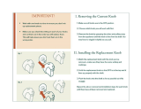
INSTALLING SHAPER CUTTERS (FIG. H, I, J, K) Fig. I
To avoid injury from an accidental start, make sure the
switch is in the OFF position and the plug is not
connected to the power source receptacle before
changing any cutters.
To use 1/2" bore shaper cutters, instali the i/2" shaper
spindle:
1. BE SURE THE MACHINE IS NOT CONNECTED TO
THE POWER SOURCE.
2. Turn the cutter depth lock handle (1) 1/4 turn
counterclockwise to unlock.
3. Raise the tool spindle (2) to its highest point by moving
the cutter depth lock handle to the right.
4. Lock the height of the tool spindle by turning the lock
handle clockwise until tight. (FIG. H)
Fig. H
5. Remove the table insert.
6. Locate the shaper spindle (3) and the shaper spindle
nut (4). The shaper spindle nut is the large nut with a
large opening at both ends, and two different types of
threads.
7 Thread the shaper spindle into the small diameter
threads in the shaper spindle nut.
8 The shoulder (5) of the threaded portion of the shaper
spindle should protrude at least 1/16" above the face
of the nut (4).
9 Maintain this 1/16" spindle position as you thread the
tapered end of the shaper spindle and nut assembly
onto the tool spindle (2) and hand tighten. (FIG. I)
10. Tighten and lock the nut (4) and shaper spindle (3)
onto the tool spindle (2) by inserting one open-end
wrench into the slot (6) under the table to hold the
flats of the tool spindle, and placing the other open-end
wrench on the shaper spindle nut (4) above the table
Tighten clockwise. (FIG. J)
Fig. J
2 3 4
I[ ]]
e
11

11. Replace the table insert.
12. Place a 1/2" bore cutter (7) (not supplied) on the
shaper spindle (3). (See "OPERATION" section for
proper arrangement of cutters and collars.)
If the cutter has a hole larger than 1/2" use bushings
to reduce the size to 1/2".
NOTE: If the cutting edge of the shaper does not
rotate in the in-feed direction and toward the backstop,
reverse the cutter or the spindle rotation, (See
"OPERATION" section).
13. Place the keyed washer (8) on the shaper spindle.
fitting the washer tab into the spindle groove (9).
14. Place the large hex nut (10) on the shaper spindle
and tighten clockwise. Use the large wrench to hold
the shaper spindle nut (4), and the smaller wrench to
tighten and lock the hex nut. (Fig. K)
Fig. K
10 m._
8
When installing shaper cutters, the keyed washer MUST
be directly under the hex jam nut. Otherwise the nut may
loosen and cause serious injury.
15. To use router bits for shaping, remove the shaper
cutter and the shaper spindle assembly by reversing
the procedure above. Be sure to unplug the tool from
the power source, before performing any assembly or
disassembly procedures.
INSTALLING ROUTER BITS (FIG. H. L)
To avoid injury from an accidental start, make sure the
switch is in the OFF position and the plug is not connected
to the power source receptacle before changing any cutters.
Install 1/2" or 1/4" router bits:
1. BE SURE THE MACHINE IS NOT CONNECTED TO
THE POWER SOURCE.
2. Remove the table insert.
-3. Turn the cutter depth lockhandle (1) 1/4 turn
counterclockwise to unlock.
4. Raise the tool spindle (2) to its highest point by moving
the cutter depth lock handle to the right.
5. Lock the height of the tool spindle by turning the lock
handle clockwise until tight. (FIG. H)
6. Locate a size collet (3) to match the size of your
router bit shank (4). Locate the router nut (5) that has
a thread in one end and a smooth type taper in the
other end.
7. Place the collet into the tapered bore of the tool
spindle (2). Place the tapered end of the router nut
over the collet and hand turn onto the spindle.
CAUTION: DO NOT TIGHTEN this or any collet without
a bit in place or the collet will crack.
8. Place the shank (4) of the router bit all the way into
the collet. Pull it back out approximately 1/16", and
tighten the router nut.
9. Insert one open-end wrench into the slot (6) under the
table to hold the flats of the tool spindle, and place the
other open-end wrench on the router; nut (5) above the
table. Tighten router nut clockwise. (FIG. L)
10.
CAUTION: Make sure that the shaper/router direction
switch is set to cut the workpiece from right to left.
Router bits cannot be inverted to cut from the opposite
direction.
To use shaper cutters for shaping, remove the router
assembly by reversing the procedure above. Be sure
to unplug the tool from the power source, before
performing any assembly or disassembly procedures.
Fig. L __?
.
12

MOUNTING THE SHAPER / ROUTER (FIG. M)
1. To mount your shaper/router in a permanent location
such as a sturdy workbench, bolt the shaper base to a
solid workbench top. The shaper base (1) has 4
mounting holes.
2. Place the shaper/router on the work surface (5), mark
the holes on the work surface and drill 3/8" holes. Use
bolts, washers, nuts to secure.
3. if the workbench moves or shakes during operation,
it must be fastened to the floor.
4. Your shaper/router is designed to be used on horizontal
surfaces only. Motor damage may result when mounted
on a non-horizontal surface.
Fig. M
t. Shaper/router
2. Hex head bolt
3. Rubber washer
4. Flatwasher
5. Workbench
6. Flatwasher
7. Lockwasher
8. Hex nut
9. Jamb nut
2
3
4
t "
1 -- !
I
5 u
I
ADJUSTMENT INSTRUCTIONS
To avoid injury from an accidental start, always make sure
the switch is OFF and the plug is removed from the power
source before making any adjustments.
ADJUSTING THE HEIGHT AND DEPTH OF CUT
(FIG. N, O)
The cutting depth can be adjusted three ways: adjusting
the spindle height, moving the fence, and by using of
spacing collars above and below the shaper cutter or
router bit. The cutting depth and alignment of both fence
sides can be individually and accurately controlled with
the help of the scales on the table.
Adjusting the spindle (FIG. N)
An adiustment is provided for convenience of installing
and removing bits and cutters, and to adjust the cutter
height for various shaping applications.
1. Unlock the cutter depth lock handle (1) on the front of
the shaper/router by turning the handle 1/4 turn
counterclockwise.
2. Move the handle to the right to raise the spindle (2),
and to the left to lower the spindle.
3. Lock the spindle in the desired position by turning the
handle clockwise until tight.
Fig. N
® ®
\ r
Adjusting the fence (FIG. O)
1. To move the entire fence position, loosen the two
knobs (1) behind the backstop (2). Slide the fence
backstop forward or backwards. The fence mounting
slots allow up to 1-1/4" adjustment.
2. Position the fence so the bit or cutter is located
directly between the fence boards (3). Tighten the
knobs securely.
3. To move the fence boards, loosen the mounting
screws (4) and nuts. The board slots allow up to
1" sideways adjustment.
4. Slide the boards toward the center until they are as
{-lose as possible to the guard (5) without touching it.
Tighten the screws and nuts securely, Use a
straightedge and the scales on the table to check
their alignment.
5. The sliding fence bracket (6) allows an individual side
adjustment of up to 1-3/4".To move the sliding bracket,
loosen the bracket knob (7).
6. Slide the bracket backwards or forwards in its grooved
track to the desired position: tighten the knob securely.
7. Proper fence settings for various cutting applications
are shown in the OPERATION section.
Fig. O
5
4 7 / 2 3
6 /
Adjusting height with spacer collars
The cutting height of shapers or router bits can be adjusted
further by placing collars below or between the cutters.
Certain requirements MUST be followed when using this
method, explained in the OPERATION section.
13

ADJUSTING THE GUARD (FIG. P)
1. The clear cutter guard (1) should always be used with
the fence, and can be rotated out of the way when
making adjustments or changing cutters.
2. Adjust the fence to the position appropriate to the
cutting job.
3. Loosen the top guard knob (2) and slide the guard to
center it over the cutter. Tighten the knob.
4. Loosen the back guard knob (3) and slide the guard
up or down to a position as low as possible between
the wooden boards, without touching the cutter, and
approximately 1/4" above the workpiece. Tighten the
knob.
Fig. P
2
]
For your own safety, do not plug the tool into the power
source receptacle or insert the switch key, until the parts
are correctly installed and adjustments have been made
To avoid possible injury, keep the guard in place and in
working order when operating the tool.
For your safety, use only shaper cutters and router bits
sized and recommended for this shaper/router. Follow
instructions that accompany the cutters.
ON / OFF SWITCH (FIG. Q)
The keyed switch is intended to prevent unauthorized
use of the shaper/router.
1. To turn the shaper/router ON insert the yellow key (1}
into the key slot (2) in the center of the switch.
2. Push the key firmly into the slot, then push switch
to the ON position to start the shaper/router.
3. To turn the shaper/router OFF push the switch to the
left position.
4. Remove the yellow switch key, when the shaper/router
has come to a complete stop, by gently pulling
it outward.
Remove the switch key whenever the shaper/router is not
in use. Place it in e safe place and out of reach of children.
Fig. Q
®
[ ]
®
FORWARD / REVERSE SWITCH (FIG. Q)
A i'orward / reverse switch (3) is located above the power
switch on the front of the shaper/router. This switch
reverses the direction of the cutters to work from left to
right or Pom right to left, increasing the wood shaping
versatility,
1 To reverse the cutter direction from counterclockwise
(right to left) to clockwise (left to right), or vice versa.
turn the tool OFF and lower the plastic switch door (4)
to expose the switch (3).
2. Depress the left side of the switch for a counterclockwise
rotation. Depress the right side for a clockwise rotation
3 BE SURE TO TURN THE CU-I-r'ER OVER to cut in
the opposite direction when changing the rotation
direction. The workpiece must always be fed against
the direction of cutter rotation.
4. Close the switch cover before turning the tool ON.
NOTE: Only shapers that can be inverted can be used
for left to right cutting. Router bits cannot be inverted
and must cut from right to left,
To avoid sudden reversal and possible injury, be sure to
close the direction switch cover before using the tool
14

To avoid injury:
!. BE SURE your cutter (1) is mounted so that the cutting
face rotates toward the in-feed fence (2). If mounted
upside down, the cutter can kick the wood back and
injure the operator. (FIG. R)
2. BE SURE the keyed washer is installed directly under
the jam nut.
3. TIGHTEN the jam nut before turning on the
shaper / router.
4. BE SURE the table insert is installed and not in contact
with the cutter.
5. DRESS PROPERLY. Do not wear glo_es, jewelry, necktie,
long sleeves, or loose clothing.
6. WEAR SAFETY goggles that comply with ANSI Z87.1,
and wear a face mask if operation is dusty.
7. EXAMINE the mounting surface to be sure the tool is
stable, with no movement.
8. BE SURE the guard is in place and locked 1/4" above
the workpiece.
Fig. R
LARGE WORKPIECES
For very long, wide, or irregularly shaped workpieces:
1. Add an extension to the sides and front of the table.
2. Use only smooth flat wood, and be sure the extension
is on the same level as the shaper/router table.
3. Replace the fence boards with longer or higher fence
extensions to provide more support.
STRAIGHT EDGE SHAPING OR ROUTING (FIG. S, T, U)
The fence should always be used if the type of shaping
work allows.
1. Draw an outline of the desired cut profile on the end of
the workpiece (1).
2. Align the fence faces with each other in a straight line
and lock them in place.
3. Rotate the cutter (2) until one of the cutting faces is
perpendicular to the fences.
4. Place the workpiece against the in-feed fence (3) and
slide it against the face of the cutter to see the cutting
profile. (FIG. S)
2 3
1
g profile
PREPARING THE WORKPIECE
Cut the workpiece as close to the final size as possible
before shaping. The shaper/router should not be used to
reduce the size of the workpiece. The spindle speed (RPM)
may be reduced if the cutter is required to make a heavy
cut. resulting in a rough or splintered cut. Always make a
test cut on a piece of scrap before shaping the final
workpiece.
Excessive depth of cut can cause kickback and possible
injury.
WOOD GRAIN
With most woods, cutting with or against the direction of
grain makes little difference, since the shaper/router runs
at a very high RPM. Shaping very open grained woods,
such as fir or redwood, may result in a rough, splintered
surface. It is advisable to make a series of light cuts. The
final cuts should remove 1/16" or less.
ACROSS THE GRAIN
Cross-grain cuts will result in splintering the back edge.
There are two ways to reduce this problem:
1. Cut the workpiece 1/4" oversize and trim after shaping.
2. Clamp a piece of scrap to the trailing edge of the
workpiece.
5. Adjust the spindle height and fence location to give the
desired cut profile.
6. Try out the setting on a piece of scrap, and make final
adjustments.
7. When about 2" of the test piece is adjacent to the
out-feed (4) side of the fence, stop the shaper and turn
the switch OFF. (FIG.T)
Fig.T
4 2 3 1
No support K-_
15

8. Clamp the test piece to the table so it will not move.
9. Loosen the three fence lock knobs holding the fence
and fence sliding bracket.
10. Slide the fence faces until they support the work
completely on both sides. (FIG. U)
11. Lock all knobs securely before turning the tool ON and
resuming the test cut.
Fig. U
4 2 3 1
Feed
NOTE: When the cutter rotation is reversed, the feed
direction will also be reversed. Therefore the in-feed (3)
and out-feed (4) fence identification will also reverse.
12. Avoid heavy cuts. Begin by positioning the cutter and
fence to remove only a small portion of the final cut
form. Increase cutter exposure with each successive
pass by moving the fence or the cutter height, until
the desired form is cut. Taking too large a cut or feeding
the workpiece too fast can cause damage to the
workpiece and loss of control with possible injury.
13. When starting the shaping operation, apply pressure
to the area supported by the in-feed fence (3), keeping
your hands away from the cutter. When m_re than half
of the workpiece has passed the cutter, transfer
pressure to the area now supported by the out-feed
fence (4).
vl 4
Never apply pressure to the workpiece in the area
between the fences. This will cause the workpiece to kick
in toward the cutter when the trailing edge leaves the
infeed fence, causing loss of control and possible injury.
CURVED EDGE SHAPING (FIG.V through AA)
To shape an edge that is not straight, remove the sliding
fence brackets and boards, and replace them with the
starting pin and a collar. A collar or bearing guide MUST
be used when cutting without a fence.
1. The collars (1) must be smooth and free of gum, pitch
or other substances. Any irregularity on the collar will
be reflected in the shaped surface.
2. The edge of the work to be shaped must be smooth.
Any irregularity in the surface that rides against the
collar will be reflected in the shaped surface.
3. The collars can be solid or ball bearing, and are
mounted above or below the cutter on the spindle
shaft to set the depth of cut.
4. A portion of the edge of the workpiece (3) MUST
remain untouched by the cutters (2) to give the
collar (1) sufficient bearing surface. (FIG. V)
5. The workpiece MUST be wide in proportion to the
cut being made. Short workpieces of narrow material
should NEVER be shaped against the collars. (FIG. W)
Fig. V
CORRECT
Sufficient bearing surface
1
INCORRECT
Insufficient bearing surface
Fig. W
CORRECT WIDTH INCORRECT WIDTH
Too Narrow
16

To position the collars (FIG. X,Y, Z)
The collars may be used above, below, or between two
cutters, according to the depth and pattern requirements.
1. When the collar (1) is placed below the cutter (2), the
progress of the cut can be seen at all times.
Accidental lifting of the workpiece (3) will gouge and
ruin it. (FIG. X)
2. When the collar is used above the cutter, the cut
cannot be seen, and the cut will not be affected by
slight variations in the wood thickness. (FIG. Y)
3. When the collar is placed between two cutters, the
cut has the benefits of both the above and below
positions. This setup is frequently used when both
edges of the work are shaped at the same time.
(FIG. Z)
Fig. X _ 3
Fig. Y
3
%
Fig. Z
4
! I
3
To feed the workpiece (FIG. AA)
The starting pin should be used as a support when
starting the cut. Always feed against the rotation of the
cutter.
1. Rest the workpiece against the starting pin (1) (first
position). Feed straight into thecutter (2) until the
finished edge is against the collar (3).
2. The workpiece is now supported by the collar and
the starting pin (second position).
3. After the cut is started, the work is swung free of the
starting pin and is supported only by the collar (third
position).
4. Keep the edge being shaped at 90°, perpendicular.
to the collar. Hold the workpiece firmly against the
collar, and slowly feed around the shape until the
cutting is complete.
Always use the starting pin. It the work advances to the
cutter without the support of the starting pin, it will be
kicked back and cause possible injury. Always feed against
the rotation of the cutter.
Fig. AA
3 2
I
2nd position
1st position
I
_ ,._ 2nd position
3rd posd_on
Using a pattern when feeding
To make several pieces of the same shape:
1. Make a pattern or template from 1/4" scrap wood.
2. Allow for the diameter of the collar, the contour
shape, and depth of cut when cutting the pattern.
3. Fasten the pattern to the workpiece using clamps,
screws, brads, or rubber cement.
4. Feed the workpieee into the cutter until the collar
contacts the pattern.
5. Slowly feed the workpiece around the pattern holding
the pattern fight against the collar. Do any cross-grain
cutting first, to prevent splintering on the finished
workpiece.
17

To avoid fire or toxic reaction, never use gasoline,
naphtha, acetone, lacquer thinner, or similar highly
volatile solvents to clean the shaper/router.
For your safety, this shaper/router is double-insulated.
To avoid electrical shock, fire. or injury, use only parts
identical to those identified in the parts list. Reassemble
exactly as the original assembly to avoid electrical shock.
Frequently blow out using an air compressor or dust
vacuum, any dust that accumulates inside the motor.
Apply a light coat of automotive paste wax to the table
top and the fence faces to reduce friction during shaping,
and to protect the surfaces.
Do not allow brake fluids, gasoline, or penetrating oils to
come in contact with plastic parts. They contain
chemicals that can damage or destroy plastics.
GENERAL MAINTENANCE
Keep your shaper/router clean and adjusted properly for
maximum performance and machine longevity. Do not
allow pitch or gums to accumulate on the table, fences,
or cutters. Clean bits and cutters frequently with a good
quality gum and pitch remover.
LUBRICATION
The shaper/router spindle shaft ball bearings are
permanently lubricated at the factory. No further
lubrication is required.
18

TROUBLESHOOTING GUIDE
Turn switch OFF and always remove plug from power source before making any adjustments or repairs.
All electrical or mechanical repairs should be done only by qualified service technicians. Contactthe nearest Sears
Service Center.
PROBLEM
Cutter does not come up 1.
to speed. 2.
Cutter slows down during 1.
operation. 2.
3.
Machine vibrates 1.
excessively.
2.
3.
Unsatisfactory cuts. 1.
2.
3.
4.
Excessive gouging at end 1.
of cuts. 2.
Chip discharge clogs. 1.
2,
3.
4.
PROBABLE CAUSE SUGGESTED CORRECTIVE ACTION
Extension cord too light or too long. 1. Replace with adequate size cord.
Low house current or overloaded 2. Reduce load on circuit or contact
circuit, your electric company.
Feeding stock too fast.
Attempting to remove too much
material.
Cutter in poor condition (gummed
or dull).
Machine not mounted to workbench
securely.
Workbench is on uneven floor.
Damaged cutter.
Dull cutter.
Feeding work in wrong direction.
Gum or pitch on cutter.
Gum or pitch on table causing
erratic feed.
Fence bracket not properly set.
Work not held firmly against fence.
Obstruction is reducing the air flow.
Cutter speed is too slow.
Wood has a high moisture content,
Cutter is too small to exhaust
the chips.
1, Decrease feed speed.
2. Decrease depth of cut, make two or more
cuts.
3. Clean or replace cutter.
1. Tighter all mounting hardware.
2. Reposition on flat, level surface.
3. Replace cutter.
1. Replace cutter.
2. Feed work against the cutter rotation.
3. Remove cutter and clean with Gum and
Pitch Remover.
4. Clean table with Gum and Pitch Remover,
1. Reset fence bracket.
2. Hold work firmly against
the out-feed fence.
1. Remove the obstruction.
2. Decrease the feed speed.
3. Decrease the feed speed.
4. Attach a Wet / Dry Vac to the
chip discharge.
19

CRAFTSMAN SHAPER / ROUTER 137.217100
When servicing use only CRAFTSMAN replacement parts. Use of any other parts may create a HAZARD or cause
product damage.
Any attempt to repair or replace electrical parts on this shaper/router may create a HAZARD unless repair is done
by a qualified service technician. Repair service is available at your nearest Sears Service Center.
Order by PART NUMBER, not by key number
Key No. Part NO. Description Size
Qty. K4_ No. Part No. Delcriptlon Size
I
2
3
4
5
6
7
8
14115501 Hex. wrench
18300202 Hex. wrench
2807CT062D Power cord
2701FBD104 Hex. nut
2641BBDA43 Round washer
hd. screw
2801ABRF01 Strata relief
83990121 Cord clamp
2668BBDA12 Round wa,sher
t'_l. screw
M4x0.7
M6x1.0-30
M4x0.7-20
1
1
1
2
4
1
1
2
47 18310201 Lock knob 2
48 14943302 Connector 1
49 2501NBDN25 Flstwasher 5/16x11/16-1/16 2
50 16932802 Lock knob 2
51 18310701 Support rod I
52 18310801 Extension plate 1
53 2501NBDN25 Fiat washer 5/16x11/16-1116 1
54 t 8311001 Lo<:_knob 1
85 2701FBD104 Hex. nut M4x0.7 2
56 14106403 Cutter guard 1
9 18301001 Nut
10 14116101 Elbow
11 8381028204 Motor
12 18301301 Nut
13 18301401 Spindle
14 14107501 Washer
15 14107401 Hex. nut
16 18402702 FOOt
17 1411;308 Washer
18 14112304 Washer
1
1
1
1
1
1
1
4
D=20.6 d=12.7 1
D-=22.2 d=12.7 1
57 2668BBDA09 Pan M. screw M4xO.7-12 2
58 2701FBD106 He,,_nut M6x1.0" 4
59 18311501 Sliding fence braoket 1
60 2501NBON16 Flat washer 1/4x3/4-1/64 5
81 18311801 Fence boa_ 2
82 2636880A42 Count hd. screw M6xt .0-25 4
18312101 Table insert I
64 18312001 Pin 1
65 18312202 Sheet bar 1
66 14608001 Pin 1
19 t 4112303 Washer
20 t 4112302 Washer
21 14112301 Washer
2.2 2801UBHA07 Strain relief
23 14018102 Switch box
24 18302505 Switch cover
25 2661ME3DE08 Truss hal. tapping
screw
26 2898087G12 Switch
27 18302803 Handle bar
D--.30.1 d=12.7 1
D=29.4 d=l 2.7 1
D=33 _=12.7 1
2
1
1
M3.5x18-18 2
28 18302901 Fiat washer 1
29 18303001 Bush 1
30 18.303104 Body shell 1
31 2615B8OC26 Hex. hd. sc,'ew and MSxl.25-30 3
washer
32 2852E55514 Switch I
33 18303.401 Spindle support 1
34 18303501 Bearing cover 1
35 26688BDA23 Pa,n hd. screw MSx0.8-8 2
36 18303702 Table I
37 18303806 Label
38 18304001 Plate cover
39 18304101 Pk,ot shaft
40 29065558Q3 Lead wire assembly
41 2806555H05 Lead wire assembly
42 18304403 Elbow
4.3 28D955HA01 Locking cabla tie
44 18304603 Warning label
45 286058H071 Switch key
46 18310101 Backstop
1
1
1
1
1
1
1
1
1
1
87 14911402 Miter gauge 1
68 2501NZDN18 Rat washer 114x3/4-1/64 1
89 14911602 Knob 1
70 2608BBLA32 Hex. sot.truss 2
hd. screw
71 260388LA38 Hex.sot. set screw MSxl.0-10 1
72 14911802 Ar_e pointer 1
73 18305301 Label 1
74 18313301 Scale 2
75 2838BSDA41 Round washer M6x1.0-18 2
hd. screw
78 16314301 Power cord damp 2
77 2708FED107 Serrated toothed M6xl.0 2
hex. flange t_t
7a 14523301 COmpressionspdng 1
79 29835L5006 Steel ball 1
13721710001 Owner's manual 1
56A 14106403A11 Curler guard assembly 1
67A 14911402A4 Miter gauge assembly 1
• Not shown
2O
/