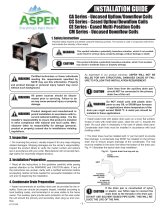
Broan REPLCOIL(01-05)HS Installation guide

Type
Installation guide
SPLIT SYSTEM UNCASED REPLACEMENT INDOOR COILS
REPLCOILXXHS HIGH SEER SERIES
INSTALLATION INSTRUCTIONS
IMPORTANT
ATTENTION INSTALLERS:
It is your responsibility to know this product better than your customer. This includes being
able to install the product according to strict safety guidelines and instructing the customer on
how to operate and maintain the equipment for the life of the product. Safety should always be
the deciding factor when installing this product and using common sense plays an important
role as well. Pay attention to all safety warnings and any other special notes highlighted in the
manual. Improper installation of the furnace or failure to follow safety warnings could result in
serious injury, death, or property damage.
These instructions are primarily intended to assist qualified individuals experienced in the proper
installation of this appliance. Some local codes require licensed installation/service personnel
for this type of equipment. Please read all instructions carefully before starting the installation.
Return these instructions to the customer’s package for future reference.
DO NOT DESTROY. PLEASE READ CAREFULLY & KEEP IN A SAFE PLACE FOR FUTURE REFERENCE.
2
IMPORTANT SAFETY INFORMATION
Please read all instructions before servicing this equipment.
Pay attention to all safety warnings and any other special
notes highlighted in the manual. Safety markings are used
frequently throughout this manual to designate a degree or
level of seriousness and should not be ignored. WARNING
indicates a potentially hazardous situation that if not avoided,
could result in personal injury or death. CAUTION indicates a
potentially hazardous situation that if not avoided, may result
in minor or moderate injury or property damage.
WARNING:
This coil is pressurized with Nitrogen at the
factory. Avoid direct face exposure or contact
with valve when gas is escaping. Always ensure
adequate ventilation is present during the
depressurization process. Any uncertainties
should be addressed before proceeding.
WARNING:
This coil must be installed in accordance
with the instructions outlined in this manual
during the installation, service, and operation
of this unit. Unqualified individuals should
not attempt to interpret these instructions or
install this equipment. If you do not posses
mechanical skills or tools, call your local dealer
for assistance. Under no circumstances should
the equipment owner attempt to install and/or
service this equipment. Failure to follow safety
recommendations could result in possible
damage to the equipment, serious personal
injury or death.
WARNING:
PROPOSITION 65 WARNING: This product
contains chemicals known to the state of
California to cause cancer, birth defects or other
reproductive harm.
• Theinstallermustcomplywithalllocalcodesandregulations
which govern the installation of this type of equipment.
Local codes and regulations take precedence over any
recommendations contained in these instructions. Consult
local building codes for special installation requirements.
• Familiarize yourself with the controls that shut off the
electrical power to the unit. If the unit needs to be shut down
for an extended period of time, turn off electrical power
atthecircuitbreaker.Foryoursafetyalwaysturnoffthe
electrical power before performing service or maintenance
on the unit.
• Installationofequipmentmayrequirebrazingoperations.
Installer must comply with safety codes and wear
appropriate safety equipment (safety glasses, work gloves,
fire extinguisher, etc.) when performing brazing operations.
• Followallprecautionsintheliterature,ontags,andon
labels provided with the equipment. Read and thoroughly
understand the instructions provided with the equipment
prior to performing the installation and operational checkout
of the equipment.
• Usecautionwhenhandlingthisequipmentorremoving
components. Personal injury can occur from sharp metal
edges present in all sheet metal constructed equipment.
GENERAL INFORMATION
Theseuncasedreplacementcoilsaredesignedforupow,
downow,orhorizontalapplications.
• Checkthecoilsoricesizeandconrmthatit’ssuitable
for application with the intended outdoor unit. Depending
onapplication,additionalinstallersuppliedoriceorTXV
may be required.
• Verify that the air delivery of the furnace/air handler is
adequate to handle the static pressure drop of the coil,
filter, and duct work.
• Ifpreciseformingofrefrigerantlinesisrequired,acopper
tubing bender is recommended. Avoid sharp bends and
contact of the refrigerant lines with metal surfaces.
• Refrigerantlinesshouldbewrappedwithpressuresensitive
neoprene or other suitable material where they pass against
sharply edged sheet metal.
• Horizontalinstallationsrequireahorizontaldrainpankit
tobeinstalled.SeeTable1(page4)forpartnumber.
COIL INSTALLATION
WARNING:
ELECTRICAL SHOCK, FIRE OR
EXPLOSION HAZARD
Failure to follow safety warnings exactly could
result in serious injury or property damage.
Improper servicing could result in dangerous
operation, serious injury, death or property
damage.
 
to the indoor blower.
 
to disconnecting. Reconnect wires correctly.
 
CAUTION:
The coil must be level to ensure proper
condensate drainage. An unlevel installation may
result in structural damage, premature equipment
failure, or possible personal injury.
NITROGEN
HEALTH
FLAMMABILITY
REACTIVITY
0 Minimal Hazard
1 Slight Hazard
1
0
0
3
Suction
Line
Liquid
Line
Cap
Schrader
Valve
Figure 1. Suction & Liquid Line Locations
1.Disconnectallelectricalpowertothefurnaceorairhandler.
2. Remove system refrigerant per industry standard practices.
3. Disconnect and remove existing evaporator coil.
System Depressurization
1.Removethecap(Figure1)fromtheendoftheliquidline.
2.Verify pressurization by depressing the Schrader valve
on the end of the liquid line. Listen for any escaping gas.
If there is no pressure, test the coil for leakage.
• Ifleakageisfound,clearlymarkthelocationoftheleak
and return the coil to the distributor for processing.
• Ifnoleaksarefound,thecoilmaybeinstalled.
3. Depress the valve to relieve all pressure from the coil.
4.Proceed to the appropriate lineset connection for
installationswithfactoryinstalledorice.Seepages4-5.
• GotoChanging the Orifice section if your installation
is with a different orifice.
• GotoInstalling a TXV kit if your installation is equipped
withaTXV.
Changing the Orifice
NOTE:Beforeproceeding,performsteps1-3intheSystem
Depressurization section and confirm that the restrictor
orifice size meets the requirements outlined in the outdoor
unitinstallationmanual.Factorysuppliedoricesizesare
listedinTable2(page4).Iftheoricemustbereplaced,
followsteps1-5.
CAUTION:
To prevent damage to the unit or internal
components, it is recommended that two
wrenches be used when loosening or tightening
nuts. Do not over tighten!
1.Usingtwowrenches,loosenthenutanddistributorbody
asshowninFigure2.Turntheassemblynutcounter-clock-
wise until the orifice body halves are separated.
2.Insertalight-gaugewirehookbetweenthedistributorbody
and the restrictor orifice while being careful not to scratch
either part. Carefully remove the restrictor orifice from the
distributorbody.SeeFigure3.
3.Checktheactualsizeoftheneworice.Thesizeisstamped
on its side. Do not use pin gauges to measure the orifice
diameter.
4.Insert the neworiceintothedistributorbody,rounded
enddown.SeeFigure4.
CAUTION:
To prevent damage to the unit or internal
components, it is recommended that two
wrenches be used when loosening or tightening
nuts. Do not over tighten!
5.Realigntheassemblynutonthedistributorbodyandhand
tighten both components. Mark a line on both bodies and
thentightenanadditional1/4turnusingtwowrenches.The
movement of the two lines will show how much the nut is
tightened.Ifatorquewrenchisused,tightento10-12ft.
lbs.or14-16Nm.
6.Proceedtotheappropriatelinesetconnectionsection.See
pages4-5.

AseparateTXVkitandC5replacementtubekitarerequired.
SeeTables3-5(page5)forproperkitpartnumbers.
CAUTION:
To prevent damage to the unit or internal
components, it is recommended that two
wrenches be used when loosening or tightening
nuts. Do not over tighten!
1.Usingtwowrenches,loosenthedistributorandliquidline
bodyhalves.Turntheassemblynutcounter-clockwise.
2. Discard the removed liquid line.
3.Insertalight-gaugewirehookbetweenthedistributorbody
and the restrictor orifice while being careful not to scratch
either part. Carefully remove the restrictor orifice from the
distributorbody.SeeFigure3.
4.Connectthedistributortotheoutletsideofthevalve.
5.BrazethenewliquidlinefromtheC5replacementtube
kitandliquidlinestub&screen(includedinTXVkit)with
drynitrogenowingthroughthejoints.



oxidation and scaling from occurring.
NOTE:Theliquidlineissoldseparately,seeTable3(page
5)forappropriatepartnumber.
6.Connecttheliquidlinetotheinletsideofthevalve.
7. Realign the assembly nut on the distributor body and hand
tighten both components. Mark a line on both bodies and
thentightenanadditional1/4turnusingtwowrenches.The
movement of the two lines will show how much the nut is
tightened.Ifatorquewrenchisused,tightento10-12ft.
lbs.or14-16Nm.
8.Usingtwowrenches,tightenbothendsofthevalve.
9. Secure the sensing bulb to the suction line using the clamp
supplied with the kit.
10.Wrapthebulb,clamp,andsuctionlinetogetherwithtar
tape or other insulating material.
IMPORTANT NOTES:
 
suction line for optimum heat transfer.
 
the suction line where condensate may accumulate.
 
the lineset.
 
12 or 6 o’clock position of the suction line. The best
location is at 4 or 8 o’clock.
4
Figure 2. 
Figure 4. 
Figure 3. Removal of Orifice
       
locations, please refer to the valve manufacturer’s
instructions.
11.RemoveanddiscardtheSchradervalvefromthesuction
header port. IMPORTANT:TheTXVwillnotfunctionif
the valve is not removed.
12.ConnecttheequalizationlinefromtheTXVtothe1/4
port located on the suction line.
CAUTION:
To prevent damage to the unit or internal
components, it is recommended that two
wrenches be used when loosening or tightening
nuts. Do not over tighten!
13.Usingtwowrenches,tightenallconnections.

HEIGHT
HORIZONTAL DRAIN
KIT PN
20” 920265
26” 920266
30” 920267
Table 1. Horizontal Drain Kits
LINESET CONNECTIONS

1.IfTXVkitandnewliquidlinearebeinginstalled,skipto
step4.
2. If original liquid line is being used, relieve all pressure from
the coil by depressing the valve on the liquid line. Remove
the valve core.
3.Usingallappropriatecautions,unbrazeandremovethe
valve holder on the liquid line.
4.Verifythelinesetendsareround,clean,andfreeofany
burrs.
5.Connectthesuctionandliquidlinesettubes.
CAUTION:
It is recommended that a wet rag be wrapped
around the suction line in front of the close
off plate before applying heat. Failure to keep
components cool during brazing may result in
structural damage, premature equipment failure,
or possible personal injury.
IMPORTANT: To prevent internal oxidation and scaling
from occuring, braze all connections with dry nitrogen

6.Brazetheindividualconnectionswithdrynitrogenowing
through the joints.
7.Wraptherefrigerantlineswithpressuresensitiveneoprene
or other suitable material especially where the lines enter
the opening in the sheet metal.
8. Proceed to Completing the Installation.
Completing the Installation
1.Checkthesystemforleaks,includingthelinesetand the
brazed joints. NOTE: Apply a soap and water solution on
each joint or union with a small paintbrush. If bubbling is
observed, the connection is not adequately sealed.
2.Evacuatethesystemofmoistureandnon-condensables
to prevent low efficiency operation or damage to the unit.
Thesuggestedrangeofevacuationis250-500microns.
3. Charge the system with refrigerant. Please Refer to the
outdoor unit installation manual for additional charging
instructions.
4.Installthecoilaccessdoor(ifremoved).
5.Properlydisposeofallremovedparts.
6.Applypowertotheunit.
PART

MODEL WIDTH
ORIFICE
SIZE
921951 REPLCOIL01HS A 0.067
921952 REPLCOIL02HS B 0.067
921953 REPLCOIL03HS B 0.080
921954 REPLCOIL04HS C 0.093
921955 REPLCOIL05HS C 0.099
NOTE:Individualrestrictorsareavailablebypartnumber-PN664***
(where***representsthesize).Example:664103isarestrictor0.103
in diameter.
Table 2. Replacement Coil Specs
5
AIR HANDLER
MODEL
AIR HANDLER
SKU
REPLACEMENT
COIL SKU
ANTEATER
COIL MODEL
ANTEATER
COIL SKU

KIT

SINGLE
B4VM-X24K-A 920770D 919626D REPLCOIL01HS 921951 920668A 921287
B4VM-X30K-A 920772D 919510D REPLCOIL01HS 921951 920669A 921287
B4VM-X24K-B 920424D 917189D* REPLCOIL02HS 921952 920668A 921288
B4VM-X30K-B 920773D 919512D REPLCOIL02HS 921952 920669A 921288
B4VM-X24K-B 920424D 920362D** REPLCOIL03HS 921953 920668A 921289
B4VM-X36K-B 920425D 917190D* REPLCOIL03HS 921953 920670A 921289
B4VM-X36K-B 920425D 919630D** REPLCOIL03HS 921953 920670A 921289
B4VM-X48K-B 920775D 919515D REPLCOIL03HS 921953 920672A 921289
B4VM-X48K-C 920426D 917191D* REPLCOIL05HS 921955 920672A 921291
B4VM-X48K-C 920426D 919517D** REPLCOIL05HS 921955 920672A 921291
B4VM-X60K-C 920427D 917192D* REPLCOIL05HS 921955 920673A 921291
B4VM-X60K-C 920427D 919518D** REPLCOIL05HS 921955 920673A 921291
B6BM-X24K-A 921312 921898 REPLCOIL01HS 921951 920669A 921287
B6BM-X30K-A 921314 921900 REPLCOIL01HS 921951 920670A 921287
B6VMAX24K-A 921164 921887 REPLCOIL01HS 921951 920669A 921287
B6VMAX30K-A 921166 921889 REPLCOIL01HS 921951 920670A 921287
B6BM-X24K-B 921313 921899 REPLCOIL02HS 921952 920669A 921288
B6BM-X30K-B 921315 921901 REPLCOIL02HS 921952 920670A 921288
B6VMAX30K-B 921167 921890 REPLCOIL02HS 921952 920670A 921288
B6BM-X36K-B 921316 921902 REPLCOIL03HS 921953 920670A 921289
B6BM-X42K-B 921317 921903 REPLCOIL03HS 921953 920671A 921289
B6VMAX24K-B 921165 921888 REPLCOIL03HS 921953 920669A 921289
B6VMAX36K-B 921168 921891 REPLCOIL03HS 921953 920670A 921289
B6VMAX42K-B 921169 921892 REPLCOIL03HS 921953 920671A 921289
B6BM-X48K-C 921318 921904 REPLCOIL05HS 921955 920672A 921291
B6BM-X60K-C 921319 921905 REPLCOIL05HS 921955 920673A 921291
B6VMAX48K-C 921171 921893 REPLCOIL05HS 921955 920672A 921291
B6VMAX60K-C 921172 921894 REPLCOIL05HS 921955 920673A 921291
*BuiltpriorJuly2008
**BuiltafterJuly2008
Table 4. Air Handler Coil Substitution Matrix
KIT
PN
KIT MODEL
A WIDTH   C WIDTH C WIDTH
    
921287 Kit,C5REPLTube,A18,1ea 1
921288 Kit,C5REPLTube,B18,1ea 1
921289 Kit,C5REPLTube,B24,1ea 1
921290 Kit,C5REPLTube,C24,1ea 1
921291 Kit,C5REPLTube,C28,1ea 1
Table 3. C5 Replacement Tube Kit PN’s
Table 5. Coil Substitution Matrix
COIL
MODEL
COIL
SKU
ANTEATER
COIL MODEL
ANTEATER
COIL SKU

KIT

SINGLE
C4BA-X24U-B 917189D
REPLCOIL02HS 921299 920669A 921288
C4BA-X24C-B 917138D
C4BH-X24C-B 917186D
C4BA-X36U-B 917190D
REPLCOIL03HS 921300 920670A 921289C4BA-X36C-B 917139D
C4BH-X36C-B 917183D
C4BA-X48U-C 917191D
REPLCOIL05HS 921302 920672A 921291C4BA-X48C-C 917140D
C4BH-X48C-C 917184D
C4BA-X60U-C 917192D
REPLCOIL05HS 921303 920673A 921291
C4BA-X60C-C 917141D
C4BH-X60C-C 917185D
6
7
709410A (Replaces7094100)
Specications&illustrationssubjecttochangewithoutnoticeorincurringobligations(07/16).
O’Fallon,MO,©NortekGlobalHVACLLC2016.AllRightsReserved.
  • Page 1 1
  • Page 2 2
  • Page 3 3
  • Page 4 4
  • Page 5 5
  • Page 6 6
  • Page 7 7
  • Page 8 8

Broan REPLCOIL(01-05)HS Installation guide

Type
Installation guide

Ask a question and I''ll find the answer in the document

Finding information in a document is now easier with AI