
E2102 Forced Convection
Oven Ranges
E2112 Forced Convection Oven
Caution: Read the instructions
before using this appliance.
INSTALLATION and
SERVICING INSTRUCTIONS
IMPORTANT
The installer must ensure that the installation of the appliance is in conformity with these instructions and
National Regulations in force at the time of installation. Particular attention MUST be paid to –
BS7671 IEE Wiring Regulations
Electricity at Work Regulations
Health And Safety At Work Act
Fire Precautions Act
This appliance has been CE-marked on the basis of compliance with the Low Voltage and EMC Directives
for the voltages stated on the Data Plate
WARNING -THIS APPLIANCE MUST BE EARTHED
On completion of the installation these instructions should be left with the Engineer-in-Charge for reference
during servicing. Further to this, The Users Instructions should be handed over to the User, having had a
demonstration of the operation and cleaning of the appliance.
IT IS MOST IMPORTANT THAT THESE INSTRUCTIONS BE CONSULTED BEFORE INSTALLING AND
COMMISSIONING THIS APPLIANCE. FAILURE TO COMPLY WITH THE SPECIFIED PROCEDURES
MAY RESULT IN DAMAGE OR THE NEED FOR A SERVICE CALL.
PREVENTATIVE MAINTENANCE CONTRACT
In order to obtain maximum performance from this unit we would recommend that a Maintenance Contract
be arranged with SERVICELINE. Visits may then be made at agreed intervals to carry out adjustments and
repairs. A quotation will be given upon request to the contact numbers below.
WEEE Directive Registration No. WEE/DC0059TT/PRO
At end of unit life, dispose of appliance and any replacement parts in a safe manner, via a
licenced waste handler.units are designed to be dismantled easily and recycling of all material
is encouraged whenever practicable.
Falcon Foodservice Equipment
HEAD OFFICE AND WORKS
Wallace View, Hillfoots Road, Stirling. FK9 5PY. Scotland.
SERVICELINE CONTACT
Phone: 01438 363 000 Fax: 01438 369 900
T100508 Ref. 12

IMPORTANT INFORMATION
Warranty Policy Shortlist
Warranty does not cover :-
Correcting faults caused by incorrect installation of a product.
Where an engineer cannot gain access to a site or a product.
Repeat commission visits.
Replacement of any parts where damage has been caused by misuse.
Engineer waiting time will be chargeable.
Routine maintenance and cleaning.
Gas conversions i.e. Natural to Propane gas.
Descaling of water products and cleaning of water sensors where
softeners/conditioners are not fitted, or are fitted and not maintained.
Blocked drains.
Independent steam generation systems.
Gas, water and electrical supply external to unit.
Light bulbs.
Re-installing vacuum in kettle jackets.
Replacement of grill burner ceramics when damage has been clearly
caused by misuse.
Where an engineer finds no fault with a product that has been reported
faulty.
Re-setting or adjustment of thermostats when unit is operating to
specification.
Cleaning and unblocking of fryer filter systems due to customer misuse.
Lubrication and adjustment of door catches.
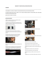
Cleaning and Maintenance
Cleaning of burner jets
Poor combustion caused by lack of cleaning
Lubrication of moving parts
Lubrication of gas cocks
Cleaning/adjustment of pilots
Correction of gas pressure to appliance.
Renewing of electric cable ends.
Replacement of fuses Corrosion caused by use of chemical cleaners.

Electrical Safety and Advice Regarding Supplementary Electrical Protection
Commercial kitchens and foodservice areas are environments where electrical appliances may be located
close to liquids, or operate in and around damp conditions, or where restricted movement for installation
and service is evident.
The installation and periodic inspection of the appliance should only be undertaken by a qualified, skilled
and competent electrician; and connected to the correct power supply suitable for load as stipulated by the
appliance data label.
The electrical installation and connections should meet the necessary requirements to local electrical
wiring regulations and electrical safety guidelines.
We recommend:-
Supplementary electrical protection with use of a residual current device (RCD).
Fixed wiring appliances incorporate a locally situated switch disconnector to connect to, which is
easily accessible for switching off and safe isolation purposes. The switch disconnector must meet
the specification requirements of IEC 60947.

SECTION 1 – INSTALLATION
UNLESS OTHERWISE STATED, PARTS WHICH HAVE BEEN
PROTECTED BY THE MANUFACTURER ARE NOT TO BE
ADJUSTED BY THE INSTALLER
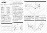
1.1 MODEL NUMBER, NETT WEIGHTS and DIMENSIONS
MODEL
WIDTH
mm
DEPT
mm
HEIGHT
mm
WEIGHT
kg
E2102 Range
3& 4 Hotplate
900
770
870
553
E2112 Oven
on Stand
900
770
1445
454
E2112/2 2
Tier Oven
900
770
1465
756
E2112 Oven
with Worktop
900
770
870
425
Optional Extras
A splashplate/plateshelf is available for fitting to the E2102 Open Top Range.
A 'lift-off' fry plate is available for use in conjunction with round hotplates.
1.2 SITING
All models other than E2112 oven on stand or legs must be installed on a non-
combustible floor. All units must be situated on a reasonably level surface. Although
the feet are adjustable and facilitate levelling, adjustment is limited.
Installation must be executed in accordance with local and/or national regulations as
listed on cover of this manual. A competent installer must be employed.
Installing Clearances
A clearance of at least 150mm must be allowed from rear of unit to any combustible
wall. 75mm clearance from any side wall is required to facilitate removal of outer side
panels during maintenance.
Where the unit requires to be positioned in close proximity to a wall, partition, kitchen
furniture, decorative finish, etc. it is recommended these be constructed of a non-
combustible material. If this is not possible then these should be clad in a suitable
non-combustible heat insulating material. Close attention should be paid to fire
prevention regulations.
A minimum vertical clearance of 900mm must be allowed between the top edge of
flue outlet and any overlying surface.
If appliance is to be installed in a suite, either centrally or adjacent to a wall with a
'boxed in' void at rear, it is important that void be adequately ventilated to ensure a
supply of air to motor cooling fan at oven rear.

1.3 ELECTRICAL SUPPLY
The units are suitable for AC supplies only. The standard terminal arrangement is for
3 phase/4 wire connection but by linking the 3 line terminals, units may be connected
to a single phase supply.
. A suitably rated isolating switch with contact separation of at least 3mm must be
installed and wiring executed in accordance with relevant regulations listed on front
cover of this manual.
1.4 SUPPLY CONNECTION
Range
Cable entry is at RH rear of appliance, at base of terminal box and is suitable for
25mm diameter conduit. A single supply will suffice for the unit, i.e. hotplates and
oven are linked internally.
Oven Only
A 32mm conduit bush cable entry is located at RH rear of appliance. The terminals
are located on electrics support panel, behind control panel.
Withdraw panel fully against stop (remove 3 screws), insert cables between cable
clamps at rear base of support panel. Connect to mains terminal. Tighten clamps to
ensure there is no strain on terminals. Cable length should be just sufficient to
enable control panel to be withdrawn fully against stop with no strain on cable.
A suitably rated isolating switch with contact separation of 3mm in all poles must be
installed and wiring executed in accordance with relevant regulations listed on front
cover of this manual.
Warning
THIS APPLIANCE MUST BE EARTHED (an earth terminal is
provided for both range and oven).
This appliance is also provided with a terminal for connection of an external
equipotential conductor. This terminal is in effective electrical contact with all fixed exposed
metal parts of the appliance, and shall allow the connection ofa conductor having a normal
cross-sectional area of up to 10mm². it is located on the rear panel and is identified by the
following symbol and must only be used for bonding purposes.
1.5 ELECTRICAL RATINGS
Electrical loadings are listed below.
Model
L1
L2
L3
E2102 3H/P Range
26.5A
26A
26A
E2102 4H/P Range
28A
26A
26A
E2112 Convection Oven
12.5A
12A
12A

.
Note
The fast plates embody a temperature limiting device which automatically switches
off part of the element circuit if plate is overheated due to being left switched on
without a pot on it.
1.6 CONTROLS
1.6.1 Oven
Indicator lamps
Red (mains) / amber (thermostat)
Thermostat
Safety Thermostat
Light 40W E14 heat resistant
Light push-button S/W
Timer (operates buzzer, audible time signal only, does not switch off oven).
Buzzer
Power switch (supplies power to controls via door switch).
Door switch (controls fan and thermostat functions, doors open - fan and heat
off/doors shut - fan and heat on).
Contactor
Fan motor 120W, rotation A/C looking on front.
2 amp fuse (1 off) motor protection
1.6.2 Hotplates
6 heat switches
Indicator lights, red - mains/amber controls
Important
After completion of installation, check unit operates satisfactorily and demonstrate
method of operation to user. Indicate location and purpose of isolating switch and
stress need to isolate appliance during cleaning or in event of an emergency. Ensure
that the person retains the User's Instruction manual.

SECTION 2 – ASSEMBLY
2.1 RANGE
a) Unpack unit and open doors. Remove all packing material.
b) Place unit in desired location. if necessary, adjust levelling bolts, access to these
at front is gained upon removal of bottom grille, below oven doors. The rear bolts are
accessible via openings in outer back panel. Do not raise unit more than is
absolutely necessary to effect levelling.
c) Check hotplates are level and free from rocking and that hotplate drip trays are
correctly located (one overlaps its neighbour).
2.2 OVEN (on 150mm Legs)
Installation procedure is as Section 2.1 but omit (c). For levelling (b), it is not
necessary in this case to remove bottom grille as levelling is now effected by turning
lower parts of the feet.
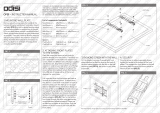
2.3 OVEN (on Stand)
a) Lift oven on to stand. Carefully align front edge of oven base with edge of stand.
From below, secure oven to stand using M6 x 35mm fixings and plain washers (2 off
at front). Use M5 x 16mm fixings and plan washers (2 off each) at rear.
b) Manoeuvre oven and stand into required location. Level assembly by turning
adjustable feet in stand.
Note
In addition to the above, feet may be secured to floor if required, using holes
provided.

Figure 1
2.4 TWO TIER MODEL (see Figure 2)
The ovens are marked as TOP and BOTTOM before leaving factory. Top unit is
identified by the addition of a worktop. Proceed as follows:-
a) Place lower oven in approximately final location.
b) Remove bottom grille from upper oven. To effect removal, undo two screws in
grille below oven doors. Remove bottom LH screw in black control panel and two
fixings at bottom of grille.
c) Lift top unit upon lower oven, taking care not to damage upturned flange at rear of
lower oven. Align rear edge of base of top oven carefully against back flange.
d) Secure top unit to lower oven using M6 x 50mm fixings provided (two at front
corners of base and two at rear, through rectangular openings in lower corners of
outer back panel).
e) Manoeuvre unit into final position and carefully level by adjusting the bolts in base
of lower oven. Do not adjust more than is necessary to achieve a true level.

Figure 2
2.5 ASSEMBLY OF SPLASHPLATE and PLATESHELF
a) Insert plate shelf standards (A) into large square holes in hob rear and press fully
home.
b) Position splash plate (B) in position with brackets resting upon and locating over
rear hob upstand.
c) Push splash plate back against standards with a spacer (F) held behind each slot
at splash plate top.
d) Insert screw (D) and washer (E) through either slot and spacer. Secure within
tapped hole of each standard.
e) Position plate shelf (C) upon horizontal arms of standards. Push it to rear and
secure to either arm using fixings provided.
f) From rear, secure standards to unit using M8 bolts and washers - 4 off (H & J).

G
C
A
E & D
`
B
I & H
Figure 3
2.6 LIFT OFF FRYPLATE
Figure 4
If a lift-off fry plate is supplied, this is placed over the circular fast boiling plates with
fat drain slot at front.
The drainage tray slides in from either side at front, below drain slot during operation.
2.7 COMMISSIONING THE APPLIANCE
2.7.1 Oven
a) Check oven linings are properly located and ensure that grid shelves slide in and
out easily. Check all packing material has been removed.
b) Switch on at mains supply. RED indicator light should illuminate.
c) With doors open, click POWER switch on, close doors and check that fan starts.
d) Set thermostat to 180Žo•C and allow oven to heat to working temperature.
AMBER light should extinguish while the keeps running.
e) Check that fan stops, elements go off and amber light goes out WHEN DOORS
ARE OPEN.

f) Check fan stops, elements go off and amber light goes out when power switch is
set to OFF with DOORS CLOSED.
g) Check timer audible time-lapse signal only (does not interrupt power to
elements).
h) Press oven lamp button, check lamp operates.
2.7.1 Hotplates
a) Switch on at mains supply. RED indicator light will illuminate.
b) Switch on all plates and check that amber indicators illuminate and that plates
heat up.

SECTION 3 – SERVICING
BEFORE ATTEMPTING ANY MAINTENANCE TASK, ISOLATE
THE APPLIANCE AT THE MAIN SWITCH AND TAKE STEPS
TO ENSURE THAT IT CANNOT BE INADVERTENTLY
SWITCHED ON.
When ordering spare parts, please quote model number; serial number and voltage
stated on data plate. This is located on a swinging plate at RH rear.
3.1 OVEN CONTROL PANEL
Access to various electrical controls, terminals, etc. can be gained upon withdrawal
of this panel. FIRST, SWITCH OFF ELECTRICITY AT THE MAINS, then remove
fixings that secure panel and draw it forward.
The various controls are removed and replaced as follows:-
3.1.1 Oven Indicator Lamps
Pull off connectors at rear and remove nut that secures lamp to panel. Withdraw
lamp from front.
Replace in reverse order.
3.1.2 Oven Light Button
Open oven control panel as detailed in Section 3.2.1.
Remove push-on connectors at rear.
Undo rear fixing nut and remove.
Replace in reverse order.
3.1.3 Oven Thermostat
Pull off connections at rear and control knob. Remove nut that secures thermostat to
panel.
Open oven doors and remove grid shelves.
Remove fixings at bottom of oven back panel. Ease panel base forward slightly and
pull it down to release top location. This will enable panel to be withdrawn from oven.
Ease RH panel rear slightly toward centre and push it back to release front location.
Remove panel from oven to reveal thermostat phial. (top phial ). Remove cover and
probe bracket that which holds capillary tube to inside wall of control compartment.
Withdraw thermostat and feed capillary tube and phial through hole in oven wall.
Replace in reverse order. Take care to replace insulating sleeving on capillary tube
and to coil excess tubing out of the way of live parts.
Note
Re-calibration of thermostat requires use of a special tool and therefore must be
adjusted by qualified personnel.
3.1.4 Safety Thermostat
Remove oven control panel as per 3.1
Disconnect two wires.
Remove cover and nut securing safety thermostat.

Remove fixings at bottom of oven back panel. Ease panel base forward slightly and
pull it down to release top location. This will enable panel to be withdrawn from oven.
Ease RH panel rear slightly toward centre and push it back to release front location.
Remove panel from oven to reveal thermostat phial. (top phial ). Remove cover and
probe bracket that which holds capillary tube to inside wall of control compartment.
Withdraw thermostat and feed capillary tube and phial through hole in oven wall.
Replace in reverse order. Take care to replace insulating sleeving on capillary tube
and to coil excess tubing out of the way of live parts.
Note
No calibration is required
3.1.5 Oven Power Switch
Pull off connections at rear. Compress plastic securing tabs inward to enable switch
to be withdrawn from front.
To replace, simply push switch into hole, ensuring it is the correct way up. Locating
tabs automatically spring into position.
3.1.6 Oven Timer
Remove connections at rear and pull off control knob. Undo nut that secures timer to
panel.
Replace in reverse order.
3.1.7 Oven Contactor, Buzzer and Capacitor
These items are mounted on electrics support, attached to control panel. These
become accessible when control panel is drawn forward.
To remove, disconnect wires from faulty component and remove fixings that secure
part to panel.
Note connection positions for correct replacement.
3.1.8 Oven Fuse
This is mounted on electrics support panel. Refer to Section 3.1.6.
When replacing, it is essential to use a fuse of correct type and rating.
Motor protection - 1 fuse (2 amp)
Note
When replacing connections, refer to wiring diagram contained in this manual from
which it can be seen that all wires are numbered.
3.2 OVEN DOOR SWITCH
To gain access, proceed as follows:-
a) Withdraw control panel.
b) Remove upper hinge cover, located immediately above oven doors. This is
achieved by removing 4 x M5 pozi screws - 2 in upper hinges and 2 concealed
within square cut-outs in lower surface of hinge cover. Withdraw cover forward.
c) Remove trip-lever by undoing fixings. This also releases return spring, take care
not to lose it.
d) Remove two screws that secure microswitch bracket and withdraw switch by
moving it down and then forward. Note location of wires (these are numbered) and
pull off connections.
e) Remove microswitch from bracket.

f) Replace all parts in reverse order.
Note
The holes in trip-lever bracket are slotted to enable switch operation to be adjusted
in relation to degree of door opening. Adjust this so that fan goes off when centre
edge of the door is opened approximately 100mm. Apply a few drops of oil to trip
lever bearing occasionally.
3.3 OVEN LAMP
To replace bulb, proceed as follows :-
a) From inside oven, pull or gently prise off glass, complete with plated bezel.
b) Unscrew bulb, taking care it does not fall behind oven back panel.
c) Fit new bulb and replace glass by pushing it until spring clips are located.
The correct type of bulb must be used, i.e. E14 240V, heat-resistant type.
3.4 OVEN FAN UNIT
This is removed from inside oven compartment as follows :-
a) Remove oven grid shelves and any other loose fitments.
b) Undo 2 screws at bottom of oven back panel and withdraw base of panel slightly
forward and downward to remove panel.
c) Remove 12 x M6 hex head screws around periphery of fan back panel insert.
d) Remove 8 x M6 nuts from studs around inner periphery.
e) Using two handles, pull fan assembly forward on to base of oven.
f) Remove wires from fan motor terminals, noting location of numbered wires, with
assembly clear of oven.
g) Dismantle inner fan from shaft by removing centre fixing screw and pulling fan off.
h) Remove motor by undoing 4 slotted screws.
j) Fit replacement motor in reverse order.
3.5 OVEN INNER LININGS - TO REMOVE
3.5.1 Oven Back Panel
Remove fixings in base. Withdraw bottom of panel slightly forward and down to
unlatch from top location.
3.5.2 Inner Side Panels
Swing inward at rear, toward oven centre. Push back to disengage from front
locating pins.
3.5.3 Bottom Plate
Lift out oven bottom plate.
3.6 OVEN ELEMENTS - TO REMOVE
a) Remove bottom grille by undoing 2 screws below oven doors. Remove bottom LH
screw in control panel and 2 screws in bottom of grille.
b) Remove oven linings as detailed in Section 3.5.
c) Remove screws that secure radiation baffle to heat exchanger and remove baffle.
d) Remove convection guides at rear of heat exchanger, noting their positions.

e) Remove clamps at rear and sides and 1 fixing at front that secures heat
exchanger.
f) Remove clamp that secures faulty element.
g) Lift up heat exchanger at front from below and support it securely to allow element
removal.
h) Disconnect flexible tails from terminal block.
j) Undo fixing nuts to remove element.
k) Replace in reverse order, referring to wiring diagram and ensuring insulation rope
is correctly located in channel.
3.7 HOTPLATE CONTROL PANEL - TO REMOVE
Remove thermostat control knob. Remove fixing at control panel ends and open both
oven doors. Pull control panel forward while slightly easing bottom edge upward.
Support control panel on doors.
3.8 HOTPLATE CONTROL SWITCHES and INDICATOR LAMPS
If any of these prove to be faulty they must be replaced. Adopt the following
procedures and refer to the appropriate wiring diagram in this manual.
3.8.1 Control Switches
Release and withdraw control panel as detailed in Section 3.1.
Remove switch connections, noting wire arrangement.
Pull off control knob.
Undo fixing screws to release switch.
Fit new switch, ensuring that serrated washers are fitted under fixing screws.
3.8.2 Indicator Lamps - To Remove
Remove control panel as detailed in Section 3.1.
Disconnect wires from lamp.
Remove nut that secures lamp to panel and withdraw lamp through control panel.
Replace in reverse order.
3.9 LARGE HOTPLATE ELEMENTS - To Remove
Remove top facia panel.
Disconnect element tails, noting their respective positions for correct replacement.
Also disconnect earth wire.
Lift hotplate evenly all round, approximately 25mm, thus releasing locating pins. Lift
up from rear, pivoting on front edge and prop plate up in this position.
Withdraw flexible tails through insulating bushes.
Lift hotplate assembly clear.
Remove insulation box and clamping plates.
Prise out faulty elements.
Note
When fitting a new element, ensure that it beds down snugly within hotplate grooves.
Tighten clamping plate evenly and firmly from centre back and check earth
connection.

Ensure no gaps are present in insulating beads and cover beads with heat resistant
insulating sleeving
Ensure that earth wire is connected by securing it to hole in control box.
Replace in reverse order.
3.10 FAST BOILING PLATES
Proceed as detailed in Section 3.9 until assembly is clear of range. Remove lower
box and disconnect beaded connections, noting their locations.
Undo nut that secures hotplate in position and remove hotplate.
When re-fitting, ensure that all earth-bonding wires are properly re-connected.

4.0 SPARES
531740330 Fan motor c/w impellor
531740340 Oven Lamp
531740410 Capacitor
531750540 Microswitch (Door)
535500002 Oven Control Knob
535500003 Timer Control Knob
535500035 Buzzer
535500036 Timer
535500037 Oven Light Switch
535500038 Power Switch
535500039 Oven Thermostat
730960010 Rectangular Hotplate Complete
730960020 Element Inner Hotplate
730960030 Element Intermediate Hotplate
730960040 Element Outer Hotplate
730960050 Round Hotplate
730960070 6 Position Switch
730962010 Neon Red
730962040 Neon Amber
731000002 Hotplate Control Knob
731000006 Mains Terminal Block 6 way
731740520 Oven Element
733630003 Safety Thermostat
734000075 Mains Terminal Block 7 Way
734240060 Fuse 2A
734310440 Contactor

E2102 3 HOTPLATE CONVECTION OVEN RANGE
E2102 4 HOTPLATE CONVECTION OVEN RANGE

E2112 CONVECTION OVEN RANGE

-
 1
1
-
 2
2
-
 3
3
-
 4
4
-
 5
5
-
 6
6
-
 7
7
-
 8
8
-
 9
9
-
 10
10
-
 11
11
-
 12
12
-
 13
13
-
 14
14
-
 15
15
-
 16
16
-
 17
17
-
 18
18
-
 19
19
-
 20
20


Falcon E2112 Installation And Servicing Instructions
- Type
- Installation And Servicing Instructions
- This manual is also suitable for
Ask a question and I''ll find the answer in the document
Finding information in a document is now easier with AI
Related papers
-
Falcon LD60 (CB985) Owner's manual
-
-
-
-
-
-
-
-
-
Other documents
-
 Raw International OFB1 User manual
-
 Raw International OPB1 User manual
-
 Hessaire 6375100 Installation guide
-
Rangemaster 90 User manual
-
-
AGA Universal Range Cooker-Gas Owner's manual
-
-
-
-


