Califone PI30 Series User manual
- Category
- Microphones
- Type
- User manual
This manual is also suitable for

Califone® International Inc. • 1145 Arroyo Avenue, # A • San Fernando, CA 91340 USA
Toll Free 800.722.0500 | Toll Free Fax 877.402.2248
International Customers call 818.407.2400 or Fax 818.407.2405 califone.com
Field Array
Speaker
Owner’s
Manual
califone.com
PI30/PI39
Series
PI39
16-Channel
UHF
Powered
Speaker
PI30-PS
Powered
Speaker
PI30-SP
Non-Powered
Speaker
ATTENTION: ALL SAFETY AND OPERATING INSTRUCTIONS
SHOULD BE READ BEFORE OPERATING APPLIANCE. ALL OPER-
ATING AND USE INSTRUCTIONS SHOULD BE FOLLOW-
ED WHEN OPERATING THE APPLIANCE. HEED AND ADHERE
TO ALL WARNINGS ON THE APPLIANCE AND IN THE OPERATING
INSTRUCTIONS. RETAIN ALL SAFETY AND OPERATING INSTRUC-
TIONS FOR FUTURE REFERENCE.
WATER & MOISTURE - DO NOT USE THE APPLIANCE NEAR
WATER; IE. BATHTUB, WASHBOWL, KITCHEN SINK, LAUNDRY
TUB, WET BASEMENT OR SWIMMING POOL.
VENTILATION - DO NOT SITUATE THE APPLIANCE SO THAT
ITS LOCATION OR POSITION INTERFERES WITH ITS PROPER
VENTILATION. FOR EXAMPLE, THE APPLIANCE SHOULD NOT
BE SITUATED ON A BED, SOFA, RUG OR SIMILAR SURFACE THAT
MAY BLOCK THE VENTILATION OPENINGS. THE
APPLIANCE SHOULD NOT BE PLACED IN A BUILT-IN
INSTALLATION, SUCH AS A BOOKCASE OR CABINET, THAT
MAY IMPEDE THE FLOW OF AIR THROUGH THE VENTILATION
OPENINGS.
HEAT - SITUATE THE APPLIANCE AWAY FROM HEAT SOURCES
SUCH AS RADIATORS, HEAT REGISTERS, STOVES OR OTHER AP-
PLIANCES (INCLUDING AMPLIFIERS) THAT PRODUCE HEAT.
POWER SOURCES - CONNECT THE APPLIANCE ONLY TO A
POWER SUPPLY TYPE DESCRIBED IN THE OPERATING INSTR-
UCTIONS OR MARKED ON THE APPLIANCE.
GROUNDING OR POLARIZATION - PRECAUTIONS SHOULD BE
TAKEN SO THAT THE GROUNDING OR POLARIZATION MEANS OF
THE APPLIANCE ARE NOT DEFEATED.
POWER CORD PROTECTION - POWER SUPPLY CORDS
SHOULD BE ROUTED SO THAT THEY ARE NOT LIKELY TO BE WALKED
ON OR PINCHED BY ITEMS PLACED UPON OR AGAINST THEM, PAY-
ING PARTICULAR ATTENTION TO CORDS
AT PLUGS, CONVENIENCE RECEPTACLES, AND THE POINT WHERE
THEY EXIT FROM THE APPLIANCE.
CLEANING - THE APPLIANCE SHOULD BE CLEANED ONLY AS REC-
OMMENDED BY THE MANUFACTURER.
NON USE PERIODS - UNPLUG THE APPLIANCE POWER CORD
FROM THE OUTLET WHEN LEFT UNUSED FOR A LONG PERIOD OF
TIME.
OBJECT & LIQUID ENTRY - CARE SHOULD BE TAKEN SO THAT
OBJECTS DO NOT FALL AND LIQUIDS ARE NOT SPILLED INTO THE
ENCLOSURE THROUGH OPENINGS.
DAMAGE REQUIRING SERVICE - THE APPLIANCE SHOULD BE SER-
VICED BY QUALIFIED SERVICE PERSONNEL WHEN: (A) THE POWER
SUPPLY CORD OR THE PLUG HAS BEEN DAMAGED (B) OBJECTS
HAVE FALLEN OR LIQUID HAS BEEN SPILLED INTO THE APPLIANCE
(C) THE APPLIANCE HAS BEEN EXPOSED TO RAIN (D) THE APPLI-
ANCE DOES NOT APPEAR TO BE OPERATING NORMALLY OR EXHIB-
ITS A MARKED CHANGE IN PERFORMANCE (E) THE APPLIANCE HAS
BEEN DROPPED OR THE ENCLOSURE DAMAGED.
SERVICING - THE USER SHOULD NOT ATTEMPT TO
SERVICE THE APPLIANCE BEYOND THAT DESCRIBED IN
THE OPERATING INSTRUCTIONS. ALL OTHER SERVICING REFER TO
A QUALIFIED SERVICE PERSONNEL.
IMPORTANT SAFETY INSTRUCTIONS
CAUTION: TO REDUCE THE RISK OF ELECTRIC SHOCK, DO NOT REMOVE COVER OR
BACK. NO USER SERVICEABLE PARTS INSIDE. REFER SERVICING TO QAULIFIED
PERSONNEL.
CAUTION
RISK OF ELECTRIC SHOCK - DO NOT OPEN
This product is not designed to
function normally in strong electro-
magnetic elds. Consequently, the
audio quality may degrade while the
product is exposed to strong electromagnetic elds.
Normal audio quality operation will be recovered
when the strong electromagnetic eld is no
longer present.
Ce produit n’est pas conçu pour
un fonctionnement dans de forts
champs électromagnétiques. Par
conséquent, la qualité sonore peut
diminuer si ce produit est exposé à
un fort champ életromagnétique. La qualité sonore
redeviendra normale après affaib-lissement du
champ électromagnétique.
The lightening ash with arrowhead
within a triangle is intended to tell the
user that parts inside the product are a
risk of electric shock to persons.
The exclamation point within a
triangle is intended to tell the user
that important operating and servicing
instructions are in the papers with
the appliance.
WARNING:
TO REDUCE THE RISK OF
FIRE OR ELECTRIC SHOCK, SO
NOT EXPOSE THIS APPLIANCE
TO RAIN OR MOISTURE.
!
!
Califone PI30/PI39 Rev 01 0609
califone_PI39_manual_rev1.indd 2-3 6/18/2009 4:14:44 PM

PI30/PI39 Series Field Array Speaker
Owner’s Manual
1 2
Thank you for purchasing this PI30/PI39 Series Field Array Speaker.
We encourage you to visit our websites, www.califone.com and www.califonepro.com, to register your product for its warranty
coverage, to sign up to receive our newsletter, download our catalog, and learn more about the complete line of Califone audio vi-
sual products, including portable and installed wireless PA systems, multimedia players and recorders, headphones and headsets,
computer peripheral equipment, visual presentation products and language learning materials.
Unpacking
Check carefully for damage which may have taken place
during transit. Report any damage claim directly to the
freight carrier immediately. If there is any damage, save the
product and packaging for inspection by the carrier’s claim
agent. Notify your dealer of the pending claim.
Warranty Registration
Please register for your 6-year warranty online
at www.califone.com to activate your warranty.
Service Repairs
Should your unit require repair contact the dealer
or Califone Service Department at: (800) 722-0500
to obtain a Return Authorization number. After
receiving the RA, ship the unit to Califone prepaid.
Collect shipments will be refused.
Contents
a) Field Array Speaker
b) AC/DC power adapter (only for use with PI39
and PI30-PS)
c) Mounting bracket with assembly hardware
d) Owner’s Manual
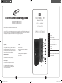
UHF channel selector
DC In jack (2)
1/4” microphone jack (2)
Audio line-out with variable volume control
Audio line-in RCA jacks (2)
Volume on/o and volume control
Power on LED
Tone control
Audio line-out with xed volume control
Wireless receiver power on/o and volume
Audio and UHF LEDs
1
2
3
4
5
6
7
8
9
10
11
PI39
1 6 C H A N N E L U H F
P O W E R E D
F I E L D A R R A Y
S P E A K E R
S P E C I F I C A T I O N S
1
2
6
2
3
9
7
8
5
5
10
11
3
4
califone_PI39_manual_rev1.indd 4-5 6/18/2009 4:14:45 PM

3 4
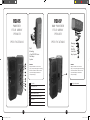
PI30-PS
P O W E R E D
F I E L D A R R A Y
S P E A K E R
S P E C I F I C A T I O N S
2
1
PI30-SP
N O N P O W E R E D
F I E L D A R R A Y
S P E A K E R
S P E C I F I C A T I O N S
1
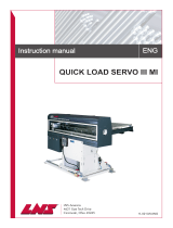
Wall
Mounting
of any PI30/PI39 Series
Field Array
Speaker
Clamping
of any
PI30/PI39
Series Field
Array Speaker
3
7
2
1
Spring-loaded terminals
1
4
5
6
4
1
2
3
4
5
6
7
DC In jack (2)
1/4” microphone jack
Audio line-out with variable volume control
Audio line-in RCA jacks (2)
Volume on/o and volume control
Tone control
Audio line-out with xed volume control
WARNING
Improper installation can cause serious
injury. Use only industry approved mounting
methods and hardware. Califone cannot be
responsible for improper installation or
subsequent damage.
WARNING
Improper installation can cause serious
injury. Use only industry approved mounting
methods and hardware. Califone cannot be
responsible for improper installation or
subsequent damage.
califone_PI39_manual_rev1.indd 6-7 6/18/2009 4:14:49 PM

Setup and Operation for Powered Array Speakers (PI39 and PI30-PS)
Power Plug the power adapter into a standard AC outlet and the DC plug into either of the DC jacks on the rear of the speaker.
Microphone
For use with a cabled microphone, plug the mic into one of the 1/4” phone jacks before turning on the power. Turn
the power ON (the red LED will light) and adjust the volume to the desired level while speaking into the microphone.
Line-In
Two pair of RCA jacks are provided to connect audio from CD, LCD Projector or other audio sources. The
Left and Right channels are “summed” because the speaker system is monaural.
Fixed and Variable Line Outs
Both the PI39 and PI30-PS have xed and variable volume line out features. With these two features, you can not only
daisy chain additional speakers for wider audio distribution, but also support functioning of an independent system
(supporting special needs students for example.) Both line outputs are the same audio mix as what’s being output by
the speaker itself. Which output is used depends on where you prefer to control the volume from.
Fixed The xed line output level is not aected by the main volume control.
Variable The variable line output level varies with the volume control setting.
Tone Control
The tone control would normally be set at 12 o’clock and will have little eect when using a microphone. When playing
music turning the control clockwise will increase the treble, while turning counter clockwise will increase the bass.
LED Indicators
There are two LED indicators behind the speaker grille. Red indicates that there is a UHF transmission signal from the
microphone. The green lights when audio is being transmitted.
PI39 16-Channel UHF Powered Speaker Only
The PI39 can receive wireless audio from any 900MHz Califone UHF transmitter (PA919SD, PA919, and wireless mics).
Wireless Receiver
If using a Califone wireless transmitter, rst make sure the transmitter and PI39 speaker are set to the same frequency.
Turn on the receiver power and adjust the volume to 10 o’clock. Then turn the speaker power and adjust the volume
level to 10 o’clock.
Wireless Microphones
There are two wireless microphone transmitters for use with the PI39; Q319 handheld microphone and M319 beltpack
transmitter used with your choice of exible collar mic (CM-316), headset mic (HBM-316), and lapel mic (LM-316).
Q319
Install battery and switch ON the Microphone. Wait 5 seconds prior to talking into the microphone. Adjust
the UHF receiver volume and speaker volume to the desired level.
M319
Install battery. Plug in one of the three available microphones.
The M319 has a volume control which should be set at the lowest level before turning on the power.
After turning the power ON gradually increase the volume to a comfortable level. As with the handheld
microphone there is a 3-5 second delay before transmitting.
Microphone Lockout
Two wireless microphones cannot be used at the same time unless one is turned o while the other is
being used. Otherwise the rst to be turned on will block out the other.
NOTES Turn the transmitter power switch o when not being used to minimize battery drain.
5 6
Specications
Speaker System (PI39, PI30-PS and PI30-SP)
Power Capacity 30 Watts RMS power capacity, 6 Ohms impedance
Sound Pressure Level: 93 dB, 1 Watt @ 1 Meter
Dispersion: -3dB @ 120 degrees o axis
Frequency Response: 250Hz to 12KHz
Transducers: Three each 3.5” Diameter, High Energy Neodymium Magnets (shielded),
10 Watts RMS capacity 3/4” Dia. Voice Coil, 16 Ohm
Amplier: 15 Watts RMS @ 5% THD
Power Source: 100-240 volt AC universal power supply
12 VDC to amplier
Dimensions: 12” H x 5” W x 4” D
Weight:
Speaker 3 lbs.
Bracket 1.3 lbs.
Compliance: Power Adapter CE, C-UL
PI39 Only
Wireless System
Receiver: One 16 channel selectable UHF diversity wireless receivers 902 - 928 MHz.
Antennas are hidden internally.
Microphone Transmitters: Handheld wireless microphone or beltpack transmitters optional.
PI39 and PI30-PS
Line In Line level RCA jacks (2) providing for audio input from CD, Tuner,
LCD projector via cable.
Line Outs Fixed and variable, RCA (2).
Mic. In 1/4” jack for microphones with a cable.
califone_PI39_manual_rev1.indd 8-9 6/18/2009 4:14:49 PM
-
 1
1
-
 2
2
-
 3
3
-
 4
4


Califone PI30 Series User manual
- Category
- Microphones
- Type
- User manual
- This manual is also suitable for
Ask a question and I''ll find the answer in the document
Finding information in a document is now easier with AI
Related papers


Other documents
-
 XIAOKOA Wireless Microphone Headset, UHF Wireless Mic Headset and Handheld 2 in 1, 160 ft (50M) Range, Rechargeable for Voice Amplifier, Stage Speakers, Teacher, Tour Guides, Fitness Instructor User manual
-
Applied Wireless PAR900M User manual
-
M-system DL30-G User manual
-
 LNS QUICK LOAD SERVO III MI User manual
-
Sanyo VPC-E10 User manual

