Page is loading ...

NOVEMBER 1998
SW721 through
SW725 (-R3) Series
KV3000, KV5000 Series
KV3100, KV5100 Series
KV3200, KV5200 Series
KV3300, KV5300 Series
FREE tech support 24 hours a day, 7 days a week: Call 724-746-5500 or fax 724-746-0746.
Mailing address: Black Box Corporation, 1000 Park Dr., Lawrence, PA 15055-1018
World-Wide Web: www.blackbox.com • E-mail: info@blackbox.com
© Copyright 2000. Black Box Corporation. All rights reserved.
Customer Support Information:
ON/OFF
SELECT
5
6
POWER
SELECT
POWER
SELECT
POWER
SELECT
POWER
8
7
SELECT
1
2
POWER
SELECT
POWER
SELECT
POWER
SELECT
POWER
4
3
POWER
-
+
R
R
SELECT
13
14
POWER
SELECT
POWER
SELECT
POWER
SELECT
POWER
16
15
SELECT
9
10
POWER
SELECT
POWER
SELECT
POWER
SELECT
POWER
12
11
ON/OFF
SELECT
5
6
POWER
SELECT
POWER
SELECT
POWER
SELECT
POWER
8
7
SELECT
1
2
POWER
SELECT
POWER
SELECT
POWER
SELECT
POWER
4
3
POWER
-
+
R
R
SELECT
13
14
POWER
SELECT
POWER
SELECT
POWER
SELECT
POWER
16
15
SELECT
9
10
POWER
SELECT
POWER
SELECT
POWER
SELECT
POWER
12
11

1
THE SERVSWITCH™ FAMILY
Welcome to the ServSwitch
TM
Family!
Thank you for purchasing a BLACK BOX
®
ServSwitch
™
Brand KVM switch! We appreciate
your business, and we think you’ll appreciate the many ways that your new ServSwitch
keyboard/video/mouse switch will save you money, time, and effort.
That’s because our ServSwitch family is all about breaking away from the traditional,
expensive model of computer management. You know, the one-size-fits-all-even-if-it-doesn’t
model that says, “One computer gets one user station, no more, no less.” Why not a single
user station (monitor, keyboard, and mouse) for multiple computers—even computers of
different platforms? Why not a pair of user stations, each of which can control multiple
computers? Why not multiple user stations for the same computer?
With our ServSwitch products, there’s no reason why not. We carry a broad line of robust
solutions for all these applications. Do you have just two PCs, and need an economical
alternative to keeping two monitors, keyboards, and mice on your desk? Or do you need to
share dozens of computers, including a mix of IBM
®
PC, RS/6000
®
, Apple
®
Macintosh
®
, Sun
Microsystems
®
, and SGI
®
compatibles, among multiple users with different access levels? Does
your switch have to sit solidly on a worktable and use relatively inexpensive cables? Or does it
have to be mounted in an equipment rack and use convenient many-to-one cables? No
matter how large or small your setup is, no matter how simple or how complex, we’re
confident we have a ServSwitch system that’s just right for you.
The ServSwitch
™
family from Black Box—the one-stop answer for all your KVM-switching
needs!
*
This manual will tell you all about your new ServSwitch or ServSwitch Ultra
™
unit,
including how to install, operate, and troubleshoot it. For an introduction to the Switch unit
itself, see Chapter 2. The ServSwitch and ServSwitch Ultra product codes covered in this
manual are (see below for accessory product codes or Appendix B for cable product codes):
SW721A-R3 KV3002MA KV3208SAE KV5002MA KV5104FAE KV5212FA
SW721AE-R3 KV3002MAE KV3212FA KV5002MAE KV5108SA KV5212FAE
SW722A-R3 KV3004MA KV3212FAE KV5004MA KV5108SAE KV5216FA
SW722AE-R3 KV3004MAE KV3216FA KV5004MAE KV5108FA KV5216FAE
KV3104FA KV3008SA KV3216FAE KV5008SA KV5108FAE KV5302MA
KV3104FAE KV3008SAE KV3302MA KV5008SAE KV5112FA KV5302MAE
KV3108SA KV3012FA KV3302MAE KV5012FA KV5112FAE KV5304MA
KV3108SAE KV3012FAE KV3304MA KV5012FAE KV5116FA KV5304MAE
SW723A-R3 KV3016FA KV3304MAE KV5016FA KV5116FAE KV5308SA
SW723AE-R3 KV3016FAE KV3308SA KV5016FAE KV5202MA KV5308SAE
SW724A-R3 KV3202MA KV3308SAE KV5102MA KV5202MAE KV5312FA
SW724AE-R3 KV3202MAE KV3312FA KV5102MAE KV5204MA KV5312FAE
SW725A-R3 KV3204MA KV3312FAE KV5104MA KV5204MAE KV5316FA
SW725AE-R3 KV3204MAE KV3316FA KV5104MAE KV5208SA KV5316FAE
KV3208SA KV3316FAE KV5104FA KV5208SAE
This manual also includes information about the acessories with these product codes (each
comes with its own installation guide if ordered separately):
SW720C-R3 KV5200C RMK19M RMK23M RMK24M
KV5000C KV5300C RMK19S RMK23S RMK24S
KV5100C RMK19F RMK23F RMK24F

2
SERVSWITCH™ AND SERVSWITCH ULTRA™
TRADEMARKS USED IN THIS MANUAL
BLACK BOX and the logo are registered trademarks, ServSwitch, ServSwitch
Ultra, Matrix ServSwitch, and ServManager are trademarks, and “The World’s
Source for Connectivity” is a service mark, of Black Box Corporation.
Apple, Mac, and Macintosh are registered trademarks, and Apple Desktop Bus and
ADB are trademarks, of Apple Computer, Inc.
ProComm is a registered trademark of DATASTORM TECHNOLOGIES, INC.™
Compaq and Alpha are registered trademarks, and DEC is a trademark, of
Compaq Computer Corporation.
HP is a registered trademark of Hewlett-Packard.
IBM, PC/AT, PS/2, RS/6000, and ThinkPad are registered trademarks, and
PC/XT is a trademark, of International Business Machines Corporation.
Helvetica and Times are registered trademarks of Linotype Company.
Logitech is a trademark of Logitech, Inc.
Microsoft and Windows are registered trademarks, and HyperTerminal and
IntelliMouse are trademarks, of Microsoft Corporation.
SGI is a registered trademark of Silicon Graphics, Inc.
Sony is a registered trademark of Sony Corporation.
Sun Microsystems is a registered trademark of Sun Microsystems, Inc.
UNIX is a registered trademark of UNIX System Laboratories, Inc.
Any other trademarks mentioned in this manual are acknowledged to be the property of the
trademark owners.

3
FCC/IC STATEMENTS
FEDERAL COMMUNICATIONS COMMISSION
AND
CANADIAN DEPARTMENT OF COMMUNICATIONS
RADIO FREQUENCY INTERFERENCE STATEMENTS
This equipment generates, uses, and can radiate radio frequency energy and if not
installed and used properly, that is, in strict accordance with the manufacturer’s
instructions, may cause interference to radio communication. It has been tested
and found to comply with the limits for a Class A computing device in accordance
with the specifications in Subpart J of Part 15 of FCC rules, which are designed to
provide reasonable protection against such interference when the equipment is
operated in a commercial environment. Operation of this equipment in a
residential area is likely to cause interference, in which case the user at his own
expense will be required to take whatever measures may be necessary to correct the
interference.
Changes or modifications not expressly approved by the party responsible for
compliance could void the user’s authority to operate the equipment.
This digital apparatus does not exceed the Class A limits for radio noise emission from digital
apparatus set out in the Radio Interference Regulation of the Canadian Department of
Communications.
Le présent appareil numérique n’émet pas de bruits radioélectriques dépassant les limites
applicables aux appareils numériques de la classe A prescrites dans le Règlement sur le
brouillage radioélectrique publié par le ministère des Communications du Canada.

4
SERVSWITCH™ AND SERVSWITCH ULTRA™
NORMAS OFICIALES MEXICANAS (NOM)
ELECTRICAL SAFETY STATEMENT
INSTRUCCIONES DE SEGURIDAD
1. Todas las instrucciones de seguridad y operación deberán ser leídas antes de
que el aparato eléctrico sea operado.
2. Las instrucciones de seguridad y operación deberán ser guardadas para
referencia futura.
3. Todas las advertencias en el aparato eléctrico y en sus instrucciones de
operación deben ser respetadas.
4. Todas las instrucciones de operación y uso deben ser seguidas.
5. El aparato eléctrico no deberá ser usado cerca del agua—por ejemplo, cerca
de la tina de baño, lavabo, sótano mojado o cerca de una alberca, etc..
6. El aparato eléctrico debe ser usado únicamente con carritos o pedestales que
sean recomendados por el fabricante.
7. El parato eléctrico debe ser montado a la pared o al techo sólo como sea
recomendado por el fabricante.
8. Servicio—El usuario no debe intentar dar servicio al equipo eléctrico más allá
a lo descrito en las instrucciones de operación. Todo otro servicio deberá ser
referido a personal de servicio calificado.
9. El aparato eléctrico debe ser situado de tal manera que su posición no
interfiera su uso. La colocación del aparato eléctrico sobre una cama, sofá,
alfombra o superficie similar puede bloquea la ventilación, no se debe colocar
en libreros o gabinetes que impidan el flujo de aire por los orificios de
ventilación.
10. El equipo eléctrico deber ser situado fuera del alcance de fuentes de calor
como radiadores, registros de calor, estufas u otros aparatos (incluyendo
amplificadores) que producen calor.
11. El aparato eléctrico deberá ser connectado a una fuente de poder sólo del
tipo descrito en el instructivo de operación, o como se indique en el aparato.

5
NOM STATEMENT
12. Precaución debe ser tomada de tal manera que la tierra fisica y la polarización
del equipo no sea eliminada.
13. Los cables de la fuente de poder deben ser guiados de tal manera que no
sean pisados ni pellizcados por objetos colocados sobre o contra ellos,
poniendo particular atención a los contactos y receptáculos donde salen del
aparato.
14. El equipo eléctrico debe ser limpiado únicamente de acuerdo a las
recomendaciones del fabricante.
15. En caso de existir, una antena externa deberá ser localizada lejos de las lineas
de energia.
16. El cable de corriente deberá ser desconectado del cuando el equipo no sea
usado por un largo periodo de tiempo.
17. Cuidado debe ser tomado de tal manera que objectos liquidos no sean
derramados sobre la cubierta u orificios de ventilación.
18. Servicio por personal calificado deberá ser provisto cuando:
A: El cable de poder o el contacto ha sido dañado; u
B: Objectos han caído o líquido ha sido derramado dentro del aparato; o
C: El aparato ha sido expuesto a la lluvia; o
D: El aparato parece no operar normalmente o muestra un cambio en su
desempeño; o
E: El aparato ha sido tirado o su cubierta ha sido dañada.

6
SERVSWITCH™ AND SERVSWITCH ULTRA™
Contents
Chapter Page
1. Specifications ........................................................................................... 10
2. Introduction ............................................................................................. 14
2.1 The Complete Package ..................................................................... 14
2.2 Operating Features ........................................................................... 14
2.3 The Front Panel ................................................................................ 16
2.4 The Rear Panel .................................................................................. 18
2.5 Cable Requirements ......................................................................... 20
2.6 Equipment Requirements ................................................................ 20
3. Installation ................................................................................................ 21
3.1 Quick Setup Guide ........................................................................... 21
3.2 Installation Procedure ...................................................................... 22
3.2.1 Rackmounting (Optional) .................................................... 22
3.2.2 Connecting the Keyboard, Monitor, and Mouse ................ 22
3.2.3 Connecting CPUs .................................................................. 23
3.2.4 Connecting Submasters (Optional) ..................................... 24
3.2.5 Powering Up the System ....................................................... 24
3.2.6 Switching from the Keyboard ............................................... 25
3.3 Cascading in ServSwitch Systems (IBM and Multiplatform
Models Only) ................................................................................ 25
3.3.1 Cable Requirements for Expansion ..................................... 26
3.3.2 Installing a Cascade ............................................................... 26
4. Operation: Hardware and Keyboard Commands .................................. 31
4.1 Guidelines for Using the ServSwitch with Your Equipment ........... 31
4.1.1 CPUs ....................................................................................... 31
4.1.2 Mouse and Keyboard ............................................................ 32
4.1.3 Monitor .................................................................................. 35
4.2 Keyboard-Command Summary ........................................................ 38
4.3 The Commands in Detail ................................................................. 41
4.3.1 Selecting a Port from the Shared Keyboard ......................... 41
4.3.2 Switching to the Next or Previous Port ................................ 41
4.3.3 Scan Mode ............................................................................. 42
4.3.4 Keep Settings ......................................................................... 42
4.3.5 Set Scan-Delay Time .............................................................. 42
4.3.6 Set Screen-Saver Interval ...................................................... 43

7
TABLE OF CONTENTS
Chapter Page
4. Operation: Hardware and Commands (continued)
4.3 The Commands in Detail (continued)
4.3.7 Set Keyboard/Mouse (IBM and Multiplatform
Regular ServSwitches Only) ........................................... 43
4.3.7.A Keyboard Types (IBM Type Keyboard Only) ........ 44
4.3.7.B Mouse Types (IBM Type Mouse Only) .................. 44
4.3.7.C Keyboard Modes ...................................................... 45
4.3.7.D Mouse Interfaces ..................................................... 46
4.3.7.E Command Procedure .............................................. 47
4.3.8 Set Maximum Ports ............................................................... 49
4.3.9 Set Width of Submasters (IBM and Multiplatform
Models Only) .................................................................... 50
4.3.10 Set Units (IBM and Multiplatform Models Only) ............... 52
4.3.11 Set Keyboard Typematic (IBM and Multiplatform Model
ServSwitches and IBM Compatible Keyboards Only) .... 54
4.3.12 Transpose Command and Alt Keys ...................................... 56
4.3.13 Reset ....................................................................................... 56
4.3.14 Send Null Byte (PS/2 Type Mice Only) .............................. 57
4.3.15 Identify ROM ......................................................................... 57
4.3.16 Send [Stop] ........................................................................... 58
4.3.17 Display Label (ServSwitch Ultra and ServSwitch with
Overlay Board Only) ......................................................... 58
4.3.18 Activate On-Screen Menus (ServSwitch Ultra and
ServSwitch with Overlay Board Only) ............................. 58
4.3.19 Activate Select Window (ServSwitch Ultra and
ServSwitch with Overlay Board Only) ............................. 59
4.4 Using the RS-232 Port ....................................................................... 60
4.4.1 Connecting Equipment to the Port ..................................... 60
4.4.2 Switching Ports Remotely (Optional) .................................. 61
4.4.3 Upgrading the Firmware (Flash Memory) .......................... 61
4.4.3.A Upgrading the Firmware with
Terminal-Emulation Software ........................................... 61
4.4.3.B Upgrading the Firmware with
the DOS COPY Command ................................................ 64
5. Operation: On-Screen Display (ServSwitch Ultra and
ServSwitch with Overlay Board Installed Only) .................................. 66
5.1 Overview ............................................................................................ 66
5.1.1 The Main Menu ..................................................................... 66
5.1.2 Navigating the Configuration Pages .................................... 67
5.1.3 Saving Changes Made with the On-Screen Display ............. 67
5.2 The “Configure System” Page .......................................................... 68
5.2.1 Configure System: Keyboard ................................................ 68
5.2.2 Configure System: Mouse ..................................................... 69
5.2.3 Configure System: Maximum Computers ........................... 71

8
SERVSWITCH™ AND SERVSWITCH ULTRA™
Contents (continued)
Chapter Page
5. Operation: On-Screen Display (continued)
5.2 The “Configure System” Page (continued)
5.2.4 Configure System: Expansion Units (IBM and
Multiplatform Models Only) ........................................... 72
5.2.5 Configure System: Expansion Width (IBM and
Multiplatform Models Only) ........................................... 72
5.2.6 Configure System: Scan Mode .............................................. 73
5.2.7 Configure System: Scan Time .............................................. 73
5.2.8 Configure System: Power-On Scan ....................................... 73
5.2.9 Configure System: Typematic Rate (IBM and
Multiplatform Models Only) ............................................ 73
5.2.10 Configure System: Typematic Delay (IBM and
Multiplatform Models Only) ........................................... 74
5.3 The “Configure Computers” Page ................................................... 75
5.3.1 Configure Computers: Computer Name ............................. 76
5.3.2 Configure Computers: Keyboard ......................................... 77
5.3.3 Configure Computers: Mouse .............................................. 78
5.4 The “Configure Overlay” Page ......................................................... 79
5.4.1 Configure Overlay: Miscellaneous ....................................... 79
5.4.1.A Color Scheme .......................................................... 79
5.4.1.B Resolution ................................................................ 80
5.4.1.C Screen Saver ............................................................. 80
5.4.1.D Screen-Saver Time ................................................... 80
5.4.2 Configure Overlay: Computer Select Window .................... 81
5.4.2.A Background Color and Text Color ........................ 81
5.4.2.B Position ..................................................................... 81
5.4.3 Configure Overlay: Computer Label ................................... 82
5.4.3.A Background Color and Text Color ........................ 82
5.4.3.B Position ..................................................................... 82
5.4.3.C Show Computer Number ........................................ 82
5.4.3.D Fade Out .................................................................. 83
5.4.3.E Font ........................................................................... 83
5.5 The “Computer Select Window” ...................................................... 84
6. Troubleshooting ...................................................................................... 85
6.1 Restoring Factory-Default Settings ................................................... 85
6.2 Common Problems ........................................................................... 86
6.2.1 CPU Doesn’t Boot ................................................................. 86
6.2.2 Can’t Switch Ports from Keyboard ....................................... 87
6.2.3 Typed Characters Wrong or Missing ................................... 87
6.2.4 Can’t Switch or Scan to Certain Ports .................................. 87
6.2.5 ServSwitch Scans or Switches to Empty Ports ...................... 88

9
TABLE OF CONTENTS
Chapter Page
6. Troubleshooting (continued)
6.2 Common Problems (continued)
6.2.6 Mouse Driver Doesn’t Load ................................................. 88
6.2.7 Can’t Access Mouse Functions ............................................. 88
6.2.8 PS/2 Mouse Gets Out of Sync .............................................. 88
6.2.9 Mouse Doesn’t Move Pointer/Cursor ................................. 89
6.2.10 Display is Fuzzy ...................................................................... 89
6.2.11 Video Not Synchronized or Wrong Color ........................... 89
6.2.12 Can’t Access High-Resolution Mode .................................... 90
6.2.13 On-Screen Display Not Synchronized .................................. 90
6.2.14 CPUs Lock Up When Windows 3.x Loaded ........................ 90
6.2.15 CPUs Have Problems Exiting Windows 3.x ......................... 91
6.2.16 ServSwitch Doesn’t Work with Docking Station .................. 91
6.2.17 ServSwitch Doesn’t Work with
Dongle-Protected Software ............................................................ 91
6.2.18 ServSwitch Doesn’t Work with IBM ThinkPad .................... 91
6.3 Calling Black Box .............................................................................. 92
6.4 Shipping and Packaging .................................................................. 92
Appendix A: NVRAM Factory Defaults ......................................................... 93
Appendix B: Cable Product Codes ................................................................ 95
Appendix C: Pinout of RS-232 Port ............................................................... 97
Appendix D: The LK461 Keyboard ............................................................... 98
Appendix E: Installing the ServSwitch Overlay Option
Board (SW720C-R3) .................................................................................. 99
E.1 Introduction ...................................................................................... 99
E.2 The Installation Procedure ............................................................ 100
Appendix F: Installing the 4-Port Expansion
Board (KV5x00C) (Full-Size Models Only) ........................................... 109
E.1 Introduction .................................................................................... 109
E.2 The Installation Procedure ............................................................ 110
Appendix G: Rackmounting Your ServSwitch ............................................ 116

10
SERVSWITCH™ AND SERVSWITCH ULTRA™
1. Specifications
Hardware
Required — Monitor that supports your computers’ highest video
standard; in multiplatform applications, should be a
multisync model capable of forming video from either
composite sync or separate horizontal and vertical sync
signals (see Section 4.1.1)
Compliance — FCC Part 15 Subpart J Class A, DOC Class/MDC classe A;
230-VAC models: CE
Standards — PC (SW72x, KV31xx, KV51xx) and multiplatform
(KV30xx, KV50xx) models:
With original Serv cabling: VGA (color or
monochrome/ page white) video;
With original Serv cabling (minimal) or coaxial cabling
(recommended): SVGA video;
With coaxial cabling: XGA (color or monochrome)
video;
Sun (KV32xx, KV52xx) and multiplatform (KV30xx,
KV50xx) models:
Sun video (coaxial cable required);
Macintosh (KV33xx, KV53xx) and multiplatform
(KV30xx, KV50xx) models:
Mac video (with either original Serv cable or
recommended coaxial cable)
Interfaces — RS-232 port (all models): Proprietary variant of TIA
RS-232 using RJ-12 (“6-wire RJ-11”) connectors, DTE;
CPU and MONITOR/KEYBOARD/MOUSE ports:
PC
(SW72x, KV31xx, KV51xx) models:
Proprietary composite of IBM PC/AT or PS/2
keyboard, RS-232 or PS/2 mouse, and video
(standards listed above);
Sun
(KV32xx, KV52xx) models:
P
roprietary composite of Sun keyboard, video, and
mouse;
Macintosh
(KV32xx, KV52xx) models:
P
roprietary composite of ADB keyboard and mouse and
Mac video;

11
CHAPTER 1: Specifications
Interfaces
(continued)— CPU and MONITOR/KEYBOARD/MOUSE ports
(continued):
Multiplatform
(KV30xx, KV50xx) models:
P
roprietary composite of:
•
IBM AT, IBM PS/2, Sun, or ADB keyboard;
• RS-232, PS/2, Sun, or ADB mouse; and
• Video (standards listed above)
Resolution — With original Serv cabling: Up to 1024 x 768
noninterlaced;
With coaxial cabling: Up to 1280 x 1024 noninterlaced;
Refer to Section 4.1.3
Protocol — RS-232: Asynchronous
Data Format — RS-232: 8 data bits, 1 stop bit, no parity (fixed)
Data Rate — RS-232: 9600 or (for firmware update only) 57,600 bps
Maximum
Distance — Depending on the CPU, monitor, and video resolution
(see Section 4.1.3), either:
40 ft. (12.2 m) of total original Serv cable from the
keyboard, monitor, and mouse to any CPU,
including up to 5 ft. (1.5 m) from any ServSwitch
or ServSwitch Ultra to any other Serv unit
(submaster) attached to it; or
20 ft. (6.1 m) of coaxial cable—possibly as much as
100 ft. (30.5 m), depending on CPUs—from any
ServSwitch or ServSwitch Ultra to any device
attached to it;
Also, 50 ft. (15.2 m) of serial cable from the RS-232 port
of any ServSwitch or ServSwitch Ultra to a non-local
computer
User Controls — Keyboard commands;
(3) Front-mounted pushbuttons:
“ON/OFF” (power), “+” (switch to next port), and
“–” (switch to previous port);
On-screen menu (ServSwitch Ultra and regular
ServSwitch with optional overlay board SW720C-R3
only)

12
SERVSWITCH™ AND SERVSWITCH ULTRA™
Indicators — SW721 and KVxx02 models: (5) Front-mounted LEDs:
(1) [Unit] POWER, (2) SELECT, (2) [CPU] POWER;
SW722 and KVxx04 models: (9) Front-mounted LEDs:
(1) [Unit] POWER, (4) SELECT, (4) [CPU] POWER;
SW723 and KVxx08 models: (9) Front-mounted LEDs:
(1) [Unit] POWER, (8) SELECT, (8) [CPU] POWER;
SW724 and KVxx12 models: (25) Front-mounted LEDs:
(1) [Unit] POWER, (12) SELECT, (12) [CPU] POWER;
SW725 and KVxx16 models: (33) Front-mounted LEDs:
(1) [Unit] POWER, (16) SELECT, (16) [CPU] POWER
Connectors — All rear-mounted;
All models:
(1) 5-pin DIN female: POWER;
(1) RJ-12 (“6-wire RJ-11”) female: RS-232;
(1) DB25 female: MONITOR/KEYBOARD/MOUSE;
SW721 and KVxx02 models: (2) DB25 female: CPU;
SW722 and KVxx04 models: (4) DB25 female: CPU;
SW723 and KVxx08 models: (8) DB25 female: CPU;
SW724 and KVxx12 models: (12) DB25 female: CPU;
SW725 and KVxx16 models: (16) DB25 female: CPU
Power — For 120-VAC, 60-Hz operation:
Mini (SW721A, SW722A, KVxx02MA, and KVxx04MA)
models:
From wallmount power supply PS023:
Optimal input: 120 VAC, 60 Hz, 100 mA;
Output: 17 VAC CT, 700 mA;
Consumption: Up to 11.9 VA (11.9 watts);
Slimline and full-size (SW723A, SW724A, SW725A,
KV3104FA, KV5104FA, KV510xFA, KVxx12FA, and
KVxx16FA) models:
From wallmount power supply PS018:
Optimal input: 120 VAC, 60 Hz, 100 mA;
Output: 16.5 VAC CT, 1.45 amps;
Consumption: Up to 23.9 VA (11.9 watts);
For 230-VAC, 50-Hz operation:
Mini (SW721AE, SW722AE, KVxx02MAE, and
KVxx04MAE) models:
From wallmount power supply PS023E:
Optimal input: 230 VAC, 50 Hz, 60 mA;
Output: 17 VAC CT, 700 mA;
Consumption: Up to 11.9 VA (11.9 watts);

13
CHAPTER 1: Specifications
Power
(continued)— For 230-VAC, 50-Hz operation (continued):
Slimline and full-size (SW723AE, SW724AE, SW725AE,
KV3104FAE, KV510xFAE, KVxx08SAE, KVxx12FAE,
and KVxx16FAE) models:
From wallmount power supply PS018E:
Optimal input: 230 VAC, 50 Hz, 60 mA;
Output: 16.5 VAC CT, 1.45 amps;
Consumption: Up to 23.9 VA (11.9 watts);
Maximum
Altitude— 10,000 ft. (3048 m)
Temperature
Tolerance— 32 to 131˚ F (0 to 55˚ C)
Humidity
Tolerance— 5 to 80% noncondensing
Enclosure — Steel
Size — Mini (SW721, KVxx02, and KVxx04M) models:
1.8" (1U) H x 8.8"W x 4.8"D (4.5 x 22.5 x 12.4 cm);
Slimline (KVxx08S) models:
1.8" (1U) H x 13.2"W x 4.8"D (4.5 x 35 x 12.4 cm);
Full-size (SW723, SW724, SW725, KV3104F, KV510xF,
KVxx12, and KVxx16) models:
3.5" (2U) H x 13.2"W x 4.8"D (8.9 x 35 x 12.4 cm)
Weight — Mini (SW721, KVxx02, and KVxx04M) models:
Net: 2.1 lb. (1 kg); Shipping: 3.8 lb. (1.7 kg);
Slimline (KVxx08S) models:
Net: 3.3 lb. (1.5 kg); Shipping: 5.8 lb. (2.6 kg);
Full-size (SW723, SW724, SW725, KV3104F, KV510xF,
KVxx12, and KVxx16) models:
Net: 5.1 lb. (2.3 kg); Shipping: 7.8 lb. (3.5 kg)

14
SERVSWITCH™ AND SERVSWITCH ULTRA™
2. Introduction
Thank you for choosing a ServSwitch™ or ServSwitch Ultra™. Designed with your
needs in mind, your new Switch will simplify your job by helping you organize your
multiple-computer application. With your Switch—depending on which model you
have—you can use one keyboard, monitor, and mouse to access a number of IBM
®
PC compatible, Apple
®
Macintosh
®
compatible, and/or Sun Microsystems
®
compatible computers, so you can significantly reduce your equipment overhead
and end keyboard and monitor clutter.
IMPORTANT NOTE
In the remainder of this manual, we will use the term “ServSwitch” to
refer to both the ServSwitch and the ServSwitch Ultra except where it is
necessary to differentiate the two.
This chapter describes everything that comes with the Switch, the external and
operating features of the Switch, and the cabling you’ll need for the Switch.
2.1 The Complete Package
Your ServSwitch package includes the Switch unit, its power supply, a modular
cable and adapter for connecting one of the unit’s RS-232 ports to a remote PC,
and this manual. If you didn’t receive everything, or if anything arrived damaged,
contact Black Box.
2.2 Operating Features
Some of the useful features of all models of the ServSwitch:
• Microprocessor-controlled keyboard and mouse switching.
• You can select the desired CPU from keyboard, front panel, or RS-232 port.
• Front-panel LEDs show the selected CPU and its power-on state.
• The units remember and restore Num Lock, Caps Lock, Scroll Lock, and
keyboard mode for each CPU.
• Screen-save function can turn off video after 1 to 999 seconds of inactivity.
• Scan function can sequence between CPUs every 1 to 15 seconds.
• You can program the keyboard’s typematic rate and delay.
• Custom settings for each CPU can be saved in nonvolatile memory.

15
CHAPTER 2: Introduction
• The units have flash memory, so you can upgrade their firmware through their
RS-232 ports.
• Rackmount kits are also available.
• Full-size 4-, 8-, and 12-port units can be expanded up to 16 ports by installing a
4-Port Expansion Board (see Appendix F).
Features exclusive to the PC and multiplatform models:
• You can access up to 256 CPUs with one keyboard, monitor, and mouse. (This
would require the maximum cascaded system of seventeen 16-port Serv units.)
• Support IBM PC compatible computers.
• Mouse can be PS/2
®
, Microsoft
®
serial, PC Mouse
®
(Mouse Systems
®
) serial, or
serial 8-bit type.
• Support all modes of PS/2 and PC/AT
®
compatible keyboards.
• Support SVGA and color or monochrome XGA or VGA video at resolutions up
to 1280 x 1024 noninterlaced (although all video types except VGA require
coaxial or special cables).
Features exclusive to the Macintosh and multiplatform models:
• Support Mac
®
compatible computers and Apple Desktop Bus™ (ADB™) mice
and keyboards.
• Support Apple video, at resolutions up to 1280 x 1024 noninterlaced, over
coaxial cables. (You’ll need a Mac Adapter for ServSwitch for each CPU that
outputs video at resolutions over 640 x 480; see the Note on page 23.)
Features exclusive to the Sun and multiplatform models:
• Support Sun compatible computers, mice, and keyboards.
• Support Sun video, at resolutions up to 1280 x 1024 noninterlaced, over
coaxial cables.
Please note that for the multiplatform models, the supported peripheral types will
depend on the CPU types. Also, the multplatform environment requires a
multisync monitor capable of syncing to the output of all your CPUs’ video cards
and of supporting their highest resolutions. Refer to Section 4.1.
The only difference between the ServSwitch and the ServSwitch Ultra is that the
ServSwitch Ultra comes from the factory with on-screen display features. These
features can be added to any regular ServSwitch by installing an optional daughter-
board, the ServSwitch Overlay Option Board (our product code SW720C-R3; see
Appendix E). Please call Black Box Technical Support for more details.

16
SERVSWITCH™ AND SERVSWITCH ULTRA™
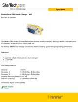
2.3 The Front Panel
The front panels of the ServSwitch feature three pushbutton switches and several
LED indicators. To familiarize yourself with these controls and indicators, refer to
Figures 2-1, 2-2, and 2-3 below and the descriptions that follow on the next page.
Figure 2-1. The front panel of a KV5x04M model (mini)
4 to 1 ServSwitch Ultra.
Figure 2-2. The front panel of a KV5x08S model (slimline)
8 to 1 ServSwitch Ultra.
Figure 2-3. The front panel of a KV5x16F model (full-size)
16 to 1 ServSwitch Ultra.

17
CHAPTER 2: Introduction
Panel Label Description
POWER Main Power LED: Lights to indicate that unit is powered ON.
ON/OFF Power Button: Pressing this button turns the unit ON and
OFF when the power supply is plugged into the unit and into
a working outlet.
CPU STATUS CPU Status LEDs: Numbered pairs of LEDs indicate the
status of the CPU or submaster (cascaded) Serv device
connected to the corresponding port on the rear panel:
SELECT (red)
Lights if the corresponding port is the currently selected port.
POWER (green)
Lights if the device on the corresponding port is powered ON.
NOTE
The mini-model chassis has 4 each of the SELECT and
[CPU] POWER LED slots. The full-size chassis has 16
each of these slots. The extra LED slots in the chassis
of the 2-port mini and the 4-, 8-, and 12-port full-size
models are left blank, but are protected by material
mounted inside the chassis.
+ (PLUS) Next Port Button: Press this button to manually switch the
shared monitor, keyboard, and mouse from the currently
selected computer to the next one in sequence.
– (MINUS) Previous Port Button: Press this button to manually switch the
shared monitor, keyboard, and mouse from the currently
selected computer to the previous one in sequence.

18
SERVSWITCH™ AND SERVSWITCH ULTRA™
2.4 The Rear Panel
All cable connections are made at the rear panel of the ServSwitch, as
illustrated in Figure 2-4 and described below.
Figure 2-4. The rear panel of a 16 to 1 ServSwitch (KV3x16F).
Panel Label Connector Description
Connect the sharing computers to these
ports with “CPU Adapter Cables.” At the
ServSwitch end these cables have a DB25
male connector; at the other ends, they
have appropriate connectors to plug into
your CPUs’ video, keyboard, and mouse
ports. These cables take the signals that
would normally pass between the CPUs’
ports and the monitor, keyboard, and
mouse, and carry them between the CPUs’
ports and the Switch instead.
You could also connect “submaster” Serv
type switches to these ports using
“ServSwitch to ServSwitch Expansion
Cables.” These cables have DB25 male
connectors at both ends; at the submaster
end, they should be plugged into a
MONITOR/KEYBOARD/MOUSE port.
Refer to Sections 2.5 and 3.2.4.
DB25 FCPU N
[N = a number
from 1 to either 2,
4, 8, 12, or 16,
depending on
which model you
have]

19
CHAPTER 2: Introduction
Panel Label Connector Description
Connect the ServSwitch’s power-supply cord
here. This is not a keyboard input. Power
transformers are available for 110 VAC or
230 VAC. Both have center-tapped output of
17 VAC at 700mA.
5-pin
DIN F
POWER
If you connect a more distant computer or
terminal to this RS-232 serial port, you’ll be able
to send switching commands to the ServSwitch
from a secondary location. You would also
connect a computer to this port to upgrade the
Switch’s firmware. Refer to Section 4.4.
RJ-12 FRS-232
Connect the shared monitor, keyboard, and
mouse to this port using an “MKM Adapter
Cable.” At the ServSwitch end, this cable has a
DB25 male connector; at the other ends, it has
appropriate connectors to plug into your
monitor, keyboard, and mouse cables. Only one
MKM Adapter Cable is needed. See Section 2.5.
DB25 FMONITOR/
KEYBOARD/
MOUSE
For each submaster you plan to connect, you
must have an Expansion Cable; you must have
an Adapter Cable for each CPU you plan to
connect. See Section 2.5.
NOTE
The mini-model chassis has 4 CPU N
connector slots. The full-size chassis
has 16 of these slots. The extra
connector slots in the chassis of the
2-port mini and the 4-, 8-, and 12-port
full-size models are left blank, but are
protected by material mounted inside
the chassis.
DB25 FCPU N
(continued)
1/121