Page is loading ...

FREE tech support 24 hours a day, 7 days a week: Call 724-746-5500 or fax 724-746-0746.
Mailing address: Black Box Corporation, 1000 Park Dr., Lawrence, PA 15055-1018
World-Wide Web: www.blackbox.com • E-mail: [email protected]
© Copyright 2000. Black Box Corporation. All rights reserved.
Customer Support Information:
Doc. No. 590-054-001 Rev. B
SEPTEMBER 2000
SERIAL MOUSE
SERIAL PORT
VGA
PS/2 MOUSE
MAC
SUN
PS/2
KEYBOARD
SPEAKERS
MIC
BLACK BOX
724- 746-5500
F
L
K
J
I
H
G
E
D
C
B
A
POWERFAIL
SELECTED
POWER
ABCDE FGH I JKLMN
KV150A-R2
KV155A
KV160A-R2
KV162RA
KV170RA
System

THE SERVSWITCH™ FAMILY
1
Welcome to the ServSwitch Family!
Thank you for purchasing a BLACK BOX
®
ServSwitch
™
Brand KVM switch! We appreciate your
business, and we think you’ll appreciate the many ways that your new ServSwitch
keyboard/video/mouse switch will save you money, time, and effort.
*
Our ServSwitch family is all about breaking away from the traditional, expensive model of
computer management and display. You know, the one-size-fits-all-even-if-it-doesn’t model that
says, “One computer gets one dedicated monitor or user station, no more, no less.” Why not a
single user station (monitor, keyboard, and mouse) for multiple computers—even computers of
different platforms? Why not a pair of user stations, each of which can control multiple
computers? Why not many monitors or user stations for the same computer? Why not access or
display any of your computers, anywhere in the world, with any of your monitors or user stations?
With our ServSwitch products, there’s no reason why not. We carry a broad line of robust
solutions for all these applications:
• Do you have just two PCs, and need an economical alternative to keeping two monitors,
keyboards, and mice on your desk? Or do you need to share dozens of computers, including a
mix of IBM
®
PC, RS/6000
®
, Apple
®
Macintosh
®
, Sun Microsystems
®
, and SGI
®
compatibles
among multiple users with different access levels?
• Do you have to send video from one computer to two different local monitors? Or do you
need to send video from multiple computers to dozens of monitors both near and far?
• Does your switch have to sit solidly on a worktable and use regular everyday cables? Or does it
have to be mounted in an equipment rack and use convenient many-to-one cables?
No matter how large or small your setup is, no matter how simple or how complex, we’re
confident we have a ServSwitch system that’s just right for you.
The ServSwitch™ family from Black Box—the one-stop answer for all your KVM-switching
needs!
*
(continued on next page)

SERVSWITCH™ MULTI
2
This manual will tell you all about your new ServSwitch Multi™, including how to install,
operate, and troubleshoot it. For an introduction to the ServSwitch Multi, see Chapter 2. The
ServSwitch Multi product codes covered in this manual are:
KV150A-R2
KV155A
KV160A-R2
KV162RA
KV170RA
This manual also includes information about the accessories with these product codes (each
comes with its own installation guide if ordered separately):
KV1601C KV1608C-R2 KV2500C
KV1602C KV1609C KV2550C-R2
KV1603C KV1701C RMK19L
KV1604C KV1702C RMK19LE
KV2000C
TRADEMARKS USED IN THIS MANUAL
BLACK BOX and the logo are registered trademarks, and ServSwitch and ServSwitch Multi are trademarks,
of Black Box Corporation.
Apple, ImageWriter, LaserWriter, Mac, and Macintosh are registered trademarks of Apple Computer, Inc.
IBM, PC/AT, PS/2, RISC System/6000, and RS/6000 are registered trademarks, and PC/XT is a trademark, of
International Business Machines Corporation.
Microsoft, HyperTerminal, IntelliMouse, and Windows are registered trademarks or trademarks of Microsoft
Corporation in the United States and/or other countries.
Sun and Sun Microsystems are registered trademarks of Sun Microsystems, Inc. in the United States and other
countries.
Any other trademarks mentioned in this manual are acknowledged to be the property of the trademark owners.

FCC, IC, AND NOM STATEMENTS
3
FEDERAL COMMUNICATIONS COMMISSION AND INDUSTRY CANADA
RADIO-FREQUENCY INTERFERENCE STATEMENTS
This equipment generates, uses, and can radiate radio frequency energy and if not installed and used properly,
that is, in strict accordance with the manufacturer’s instructions, may cause interference to radio
communication. It has been tested and found to comply with the limits for a Class A computing device in
accordance with the specifications in Subpart J of Part 15 of FCC rules, which are designed to provide
reasonable protection against such interference when the equipment is operated in a commercial
environment. Operation of this equipment in a residential area is likely to cause interference, in which case the
user at his own expense will be required to take whatever measures may be necessary to correct the
interference.
Changes or modifications not expressly approved by the party responsible for compliance could void the user’s
authority to operate the equipment.
This digital apparatus does not exceed the Class A limits for radio noise emission from digital apparatus set out in the Radio
Interference Regulation of Industry Canada.
Le présent appareil numérique n’émet pas de bruits radioélectriques dépassant les limites applicables aux appareils numériques
de la classe A prescrites dans le Règlement sur le brouillage radioélectrique publié par Industrie Canada.
INSTRUCCIONES DE SEGURIDAD (Normas Oficiales Mexicanas Electrical-Safety Statement)
1. Todas las instrucciones de seguridad y operación deberán ser leídas antes de que el aparato eléctrico sea
operado.
2. Las instrucciones de seguridad y operación deberán ser guardadas para referencia futura.
3. Todas las advertencias en el aparato eléctrico y en sus instrucciones de operación deben ser respetadas.
4. Todas las instrucciones de operación y uso deben ser seguidas.
5. El aparato eléctrico no deberá ser usado cerca del agua—por ejemplo, cerca de la tina de baño, lavabo,
sótano mojado o cerca de una alberca, etc..
6. El aparato eléctrico debe ser usado únicamente con carritos o pedestales que sean recomendados por el
fabricante.
7. El aparato eléctrico debe ser montado a la pared o al techo sólo como sea recomendado por el fabricante.
8. Servicio—El usuario no debe intentar dar servicio al equipo eléctrico más allá a lo descrito en las
instrucciones de operación. Todo otro servicio deberá ser referido a personal de servicio calificado.
9. El aparato eléctrico debe ser situado de tal manera que su posición no interfiera su uso. La colocación del
aparato eléctrico sobre una cama, sofá, alfombra o superficie similar puede bloquea la ventilación, no se
debe colocar en libreros o gabinetes que impidan el flujo de aire por los orificios de ventilación.
10. El equipo eléctrico deber ser situado fuera del alcance de fuentes de calor como radiadores, registros de
calor, estufas u otros aparatos (incluyendo amplificadores) que producen calor.
11. El aparato eléctrico deberá ser connectado a una fuente de poder sólo del tipo descrito en el instructivo de
operación, o como se indique en el aparato.

SERVSWITCH™ MULTI
4
12. Precaución debe ser tomada de tal manera que la tierra fisica y la polarización del equipo no sea
eliminada.
13. Los cables de la fuente de poder deben ser guiados de tal manera que no sean pisados ni pellizcados por
objetos colocados sobre o contra ellos, poniendo particular atención a los contactos y receptáculos donde
salen del aparato.
14. El equipo eléctrico debe ser limpiado únicamente de acuerdo a las recomendaciones del fabricante.
15. En caso de existir, una antena externa deberá ser localizada lejos de las lineas de energia.
16. El cable de corriente deberá ser desconectado del cuando el equipo no sea usado por un largo periodo de
tiempo.
17. Cuidado debe ser tomado de tal manera que objectos liquidos no sean derramados sobre la cubierta u
orificios de ventilación.
18. Servicio por personal calificado deberá ser provisto cuando:
A: El cable de poder o el contacto ha sido dañado; u
B: Objectos han caído o líquido ha sido derramado dentro del aparato; o
C: El aparato ha sido expuesto a la lluvia; o
D: El aparato parece no operar normalmente o muestra un cambio en su desempeño; o
E: El aparato ha sido tirado o su cubierta ha sido dañada.

TABLE OF CONTENTS
5
Contents
Chapter Page
1. Specifications .......................................................................................................................................... 10
2. Introduction ........................................................................................................................................... 14
2.1 Overview .......................................................................................................................................... 14
2.2 Features and Benefits ...................................................................................................................... 15
2.3 A Typical Application ...................................................................................................................... 16
2.4 Limitations and Restrictions ........................................................................................................... 17
2.5 Safety Precautions ........................................................................................................................... 18
2.6 The System and Its Components ................................................................................................... 18
2.6.1 The Complete ServSwitch Multi Package and Other Components You’ll Need .............. 18
2.6.2 Rackmounting the ServSwitch Multi (Optional) ............................................................... 19
2.6.3 Descriptions of the ServSwitch Multi Base Unit and MX and Their Components .......... 20
2.6.4 Descriptions of the ServSwitch Multi EXP and SB and Their Components ..................... 23
2.6.5 Descriptions of the ServSwitch Multi Hub and Its Components ....................................... 26
3. Installing User-Interface Cards, User Cables, and Console Devices ................................................... 27
3.1 Connecting Local-Console Equipment to a Base Unit or MX ..................................................... 27
3.2 Installing User-Interface Cards in a ServSwitch Multi ................................................................. 28
3.3 Connecting User Cables and Console Equipment to Your User Cards ....................................... 30
3.3.1 For IBM Style Keyboard and Mouse .................................................................................... 31
3.3.2 For Apple Macintosh Style Keyboard and Mouse ............................................................... 32
3.3.3 For Sun Microsystems Keyboard and Mouse ...................................................................... 33
3.3.4 Connecting Non-Multisync Monitors .................................................................................. 34
3.3.5 Connecting Dual Monitors (UICD Only) ........................................................................... 35
4. Installing CPU-Interface Cards, Server Cables, and Computers ......................................................... 37
4.1 Setting the Jumpers to Configure the Video-Output Type .......................................................... 37
4.2 Setting the DIP Switch .................................................................................................................... 39
4.2.1 Configuring Video Options .................................................................................................39
4.2.2 Setting the Keyboard/Mouse-Inactivity Timeout ............................................................... 40
4.2.3 Setting the Keyboard Translation (Mapping) for Macintosh Computers ........................ 40
4.3 Installing CPU-Interface Cards in a ServSwitch Multi .................................................................. 41
4.4 Connecting the Server Cables and Computer Equipment .......................................................... 43
4.4.1 For IBM PS/2 or PC/AT Compatible Computers .............................................................. 44
4.4.2 For Apple Macintosh Compatible Computers .................................................................... 45
4.4.3 For Sun Microsystems Compatible Computers .................................................................. 46
4.4.4 For RS/6000 and SGI Compatible Computers ................................................................... 47

SERVSWITCH™ MULTI
6
Contents (cont’d)
Chapter Page
5. Installing Management and Serial Control Cards and Associated Equipment .................................. 48
5.1 Overview of the Cards ..................................................................................................................... 48
5.2 The Cards and Cables Illustrated ................................................................................................... 49
5.3 Installing the Cards ......................................................................................................................... 50
5.4 Attaching Terminals to the Serial Control Card ........................................................................... 51
6. Planning and Installing an Expanded System (Optional) .................................................................. 52
6.1 Placing the ServSwitch Multi .......................................................................................................... 54
6.2 Determining Where to Install Cards and Attach Equipment ...................................................... 56
6.3 Configuring Your Expansion Cards ............................................................................................... 58
6.3.1 Setting the Transmit Card’s Unit-Address DIP Switch ....................................................... 58
6.3.2 Setting the Distance Jumpers on the Transmit and Receive Cards ................................... 60
6.4 Installing Your Expansion Cards .................................................................................................... 62
6.5 Installing Your Expansion Cables .................................................................................................. 63
6.6 Inspecting Your Expanded System ................................................................................................. 63
7. The ServSwitch Multi Hub ..................................................................................................................... 64
7.1 Overview .......................................................................................................................................... 64
7.2 Features and Benefits ...................................................................................................................... 66
7.3 Installing the Hub ........................................................................................................................... 66
7.4 The Functions of the Hub’s LEDs .................................................................................................. 70
7.5 The Functions of the Hub’s LCD Panel and Pushbuttons ........................................................... 71
7.5.1 The Idle Display Screen ....................................................................................................... 71
7.5.2 The Contrast Screen ............................................................................................................. 72
7.5.3 The Chassis ID and Change ID Screens .............................................................................. 72
7.5.4 The Installed Modules and Module Details Screens .......................................................... 73
7.5.5 The System Status and Status Details Screens .................................................................... 73
7.5.6 The Serial Port and Edit Mode Screens .............................................................................. 74
7.5.7 The Link Status, Select Slot, and Select Port Screens ........................................................ 74
7.5.8 The Language and Change Language Screens .................................................................. 75
7.6 Flash Upgrading .............................................................................................................................. 75
7.7 Sample System Configurations ....................................................................................................... 76
7.7.1 A 16 x 128 Matrix ................................................................................................................. 76
7.7.2 A 16 x 384 Matrix ................................................................................................................. 77
7.7.3 A 32 x 256 Matrix ................................................................................................................. 78

TABLE OF CONTENTS
7
Chapter Page
8. Operation ............................................................................................................................................... 79
8.1 Basic Operation ............................................................................................................................. 79
8.2 Keyboard Control .......................................................................................................................... 81
8.2.1 Keystroke Notation ............................................................................................................. 81
8.2.2 Keyboard-Based Switching ..................................................................................................81
8.3 Multiuser Operation ...................................................................................................................... 82
8.4 Multiplatform Keyboard Mapping (Character Translation) ...................................................... 84
8.5 Audio and Serial Functions (Audio Cables Only) ....................................................................... 89
8.6 Channel Scanning ......................................................................................................................... 90
8.7 Broadcast Mode ............................................................................................................................. 91
8.8 Follow Mode ................................................................................................................................... 92
8.9 Swap Mode...................................................................................................................................... 92
8.10 Privacy Mode .................................................................................................................................. 92
8.11 Command Forwarding .................................................................................................................. 93
8.12 Choosing an Alternate Command-Mode Hotkey ........................................................................ 93
8.13 Upgrading Card/Module Firmware Through Consoles’ Serial Ports ....................................... 94
8.14 Overriding the Settings of a CPU-Interface Card’s DIP Switches ............................................... 98
8.15 Other Commands: System Control and Maintenance ................................................................ 99
9. Using the On-Screen Display (UICD Consoles Only) ....................................................................... 101
9.1 Display Overview .......................................................................................................................... 101
9.1.1 Features .............................................................................................................................. 101
9.1.2 Logging In and Out of the System ................................................................................... 101
9.2 The On-Screen Menus ................................................................................................................ 102
9.2.1 The Channel-List Menu .................................................................................................... 102
9.2.2 The User-List Menu (Administrator Only) ..................................................................... 103
9.2.3 The User/Administrator-Controls Menu ........................................................................ 104
9.2.3.A Scanning ............................................................................................................... 104
9.2.3.B Menu Activation ................................................................................................... 104
9.2.3.C Switch Alt. User Module ...................................................................................... 105
9.2.3.D Control Alt. User Module ................................................................................... 105
9.2.4 The Command-Line Entry Window .................................................................................. 106
9.3 Administrator Functions in the Channel-List and User-List Menus (Administrator Only) ..... 107
9.3.1 Channel-List Menu Functions ........................................................................................... 107
9.3.1.A Adding New Computer-Channel Configurations ............................................... 107
9.3.1.B Editing Computer-Channel Configurations ........................................................ 108
9.3.1.C Deleting Computer-Channel Configurations ..................................................... 108
9.3.2 User-List Menu Functions .................................................................................................. 110
9.3.2.A Administrator Setup ............................................................................................. 110
9.3.2.B Adding New User Profiles .................................................................................... 110
9.3.2.C Editing User Profiles ............................................................................................. 110
9.3.2.D Deleting User Profiles .......................................................................................... 110
9.3.2.E Setting Users’ Access Privileges ............................................................................ 111

SERVSWITCH™ MULTI
8
Contents (cont’d)
Chapter Page
9. Using the On-Screen Display (continued)
9.4 Administrator Controls (Administrator Only) .......................................................................... 112
9.4.1 Broadcasting (Enable/Disable Broadcast Mode) ........................................................... 112
9.4.2 Confirm Deletes (Enable/Disable Delete Confirmation) .............................................. 112
9.4.3 System Configuration (Configure System Functions) .................................................... 112
9.4.3.A Chassis Number ................................................................................................... 112
9.4.3.B Command Key Sequence .................................................................................... 113
9.4.3.C Menu Activation Key Sequence .......................................................................... 113
9.4.3.D Remote Commands ............................................................................................. 113
9.4.3.E Remap Windows Keys .......................................................................................... 113
9.4.3.F Standalone RSP .................................................................................................... 113
9.4.3.G Follow/Swap Feature Status ............................................................................... 113
9.4.3.H Card Address for Dual-Monitor Support............................................................ 113
9.4.4 Configuration Control (Transfer Configuration Settings) ............................................. 114
9.5 Using the On-Screen Display with a Non-Multisync Monitor ................................................... 114
10. Using Management and Serial Control Cards .................................................................................... 115
10.1 Addressing Terminals on the Serial Control Card ................................................................... 115
10.2 Getting Started: The Options Screen ........................................................................................ 116
10.3 The Main On-Screen Menus ..................................................................................................... 117
10.3.1 The Channel-List Menu ................................................................................................. 117
10.3.1.A Functions ........................................................................................................ 117
10.3.1.B Searching the Channel List ........................................................................... 118
10.3.1.C Crossloading the Channel List ...................................................................... 118
10.3.2 The Administrator-Controls Menu ............................................................................... 118
10.3.3 The Open-Session Menu ............................................................................................... 119
10.3.3.A What Is “Opening a Session”? ........................................................................ 119
10.3.3.B How to Open a Session .................................................................................. 119
10.3.3.C
How To Make Your Session Persistent and Scrollable (Using History Mode)
.. 120
10.3.3.D How to Close a Session .................................................................................. 120
10.4 Using the System Management Tools ....................................................................................... 121
10.4.1 Display Chassis Configuration ....................................................................................... 122
10.4.2 Display Flash ROM Status .............................................................................................. 123
10.4.3 Download Local to Remote Flash ROM (Crossload Firmware Between Cards) ........ 124
10.4.4 Download Serial Port to Flash ROM (Download Firmware to a Card) ...................... 125
10.4.5 Search for Connected Chassis ....................................................................................... 126
10.4.6 Set Date and Time ......................................................................................................... 126
10.4.7 Transfer Security Log ..................................................................................................... 127
10.4.8 Transfer Channel List .................................................................................................... 128
10.4.9 Main Menu Serial Port Enable/Disable ....................................................................... 128
10.5 Using the Security Monitor ....................................................................................................... 129
10.5.1 The Active User List ....................................................................................................... 130
10.5.2 The Alert Message Window ........................................................................................... 130
10.5.3 The Log Window ............................................................................................................ 131

TABLE OF CONTENTS
9
Chapter Page
11. Troubleshooting ................................................................................................................................... 132
11.1 Common Problems .................................................................................................................... 132
11.1.1 A ServSwitch Multi’s Front-Panel LEDs Are Blinking ................................................ 132
11.1.2 The LEDs for a Transmit-Card or Receive-Card Channel Do Not Light .................. 132
11.1.3 A Channel Cannot Be Selected ................................................................................... 132
11.1.4 A Computer Channel Can Be Selected, But You’re Not Getting
Any Video From the Computer ................................................................................ 133
11.1.5 Computer Video Can Be Seen But Is Distorted, Discolored, Out of Sync, or
Otherwise Degraded ................................................................................................... 133
11.1.6 Video Can Be Seen But Is Superimposed on Another Computer’s Video ............... 134
11.1.7 Video Blanks Out Unexpectedly ................................................................................. 134
11.1.8 The On-Screen Display Doesn’t Appear ..................................................................... 134
11.1.9 An RS/6000 Keyboard Is Not Responding ................................................................. 134
11.1.10 A Keyboard Doesn’t Work ............................................................................................ 134
11.1.11 A Mouse Doesn’t Work ................................................................................................. 135
11.1.12 A Serial Device Doesn’t Work ...................................................................................... 135
11.1.13 A Pair of Speakers/Headphones Doesn’t Work ......................................................... 136
11.1.14 A Microphone Doesn’t Work ....................................................................................... 136
11.2 Calling Black Box ....................................................................................................................... 137
11.3 Shipping and Packaging ............................................................................................................ 137
Appendix A: Configuration Charts ............................................................................................................. 138
Appendix B: Problem Report ..................................................................................................................... 146
Appendix C: DIP-Switch Settings and Their Numeric Equivalents .......................................................... 147
Appendix D: Cables ..................................................................................................................................... 149
D.1 CPU (Server) Cables ................................................................................................................... 149
D.2 User Cables .................................................................................................................................. 150
D.3 Adapters ....................................................................................................................................... 151
Appendix E: Making Nonstandard Serial Connections ............................................................................ 152
Appendix F: Rackmounting the Base Unit or EXP ................................................................................... 153

SERVSWITCH™ MULTI
10
1. Specifications
Compliance — FCC Part 15 Subpart J Class A, IC Class/classe A
Standards — VGA, SVGA, XGA, XGA-2, Macintosh, or Sun video; can also carry
RS/6000, SGI, or RGsB-on-BNC video with the proper adapters
Interfaces — Base Unit (KV150A-R2) and MX (KV155A) only: On front panel:
Serial port and serial mouse port: EIA/TIA RS-232 pinned to TIA-574;
VGA port: VGA;
PS/2 keyboard and PS/2 mouse ports: IBM PS/2 peripheral input;
Mac port: ADB;
Sun port: Sun peripheral input;
Mic port: Standard mono audio input;
Speakers port: Standard stereo audio output;
Hub (KV170RA) only:
Front-mounted serial port (not currently enabled): EIA/TIA RS-232
proprietarily pinned on RJ-45;
On CPU-Interface, User-Interface, and Expansion Cards:
Proprietary composites of:
• IBM PC/AT, IBM PS/2, ADB, or Sun keyboard;
• RS-232, PS/2, ADB, or Sun mouse;
• Video (standards listed above);
• Mono audio; and
• Stereo audio
Resolution — At up to 90 Hz: Up to 1280 x 1024 noninterlaced;
At up to 60 Hz: Up to 1600 x 1280 noninterlaced;
Maximum video bandwidth is 155 MHz
Protocol — RS-232: Asynchronous
Data Format — RS-232 connections to CPU and User Cards: Transparent to data format;
RS-232 connections to Serial Control Cards: 7 or 8 data bits; even, odd, or
no parity; 1 or 2 stop bits (user-selectable)
Data Rate — RS-232 connections to CPU and User Cards: Transparent to data rates
up to 9600 bps with hardware flow control or up to 115.2 kbps with
software flow control;
RS-232 connections to Serial Control Cards: 19,200, 9600, 4800, 2400, or
1200 bps (user-selectable)
Flow Control — RS-232: Hardware (RTS/CTS), software (X-ON/X-OFF), or none:
Connections to CPU and User Cards: Autosensed;
Connections to Serial Control Cards: User-selectable
Audio Response — Microphone input and stereo output: From 20 Hz to 20 kHz at ±3 dB

CHAPTER 1: Specifications
11
Maximum Distance — 20 ft. (6.1 m) to any attached keyboard, monitor, and mouse;
30 ft. (9.1 m) to any attached CPU;
500 ft. (152.4 m) of total cabling between the highest-level cascaded
ServSwitch Multi (the one to which the monitor/keyboard/mouse
stations are attached) and the lowest-level ServSwitch Multi (the one to
which the CPUs are attached)
User Controls — For Hub (KV170RA):
(4) Front-mounted menu-control pushbuttons;
(1) Rear-mounted ON/OFF rocker switches (one for each of the two
power-supply modules);
On Transmit Modules (KV1701C): (3) 6-position distance DIP
switches;
On Receive Modules (KV1702C): (3) 2-position distance DIP switches;
For all other models:
Keyboard commands;
(1) Rear-mounted ON/OFF rocker switch;
With KV2550C-R2 installed: On-screen menus;
With KV1608C-R2 installed: Serial management menu;
On Base Unit (KV150A-R2): (12) Port-selection pushbuttons (1 for
each port);
On MX (KV155A): (4) Port-selection pushbuttons (1 for each port);
On CPU-interface cards:
(6) Jumpers for video type;
(1) 8-position DIP switch for various options
Indicators — All front-mounted on all models;
On Base Unit (KV150A-R2):
(1) 2-character display panel (5-x-9-pixel area for each character);
(12) Selected-port LEDs (one for each port);
On MX (KV155A):
(6) LEDs:
(1) Power;
(1) Fail;
(4) Selected port (one for each port);
On EXP (KV160A-R2) and SB (KV162RA):
(30) LEDs:
(1) Power;
(1) Fail;
(14) Selected port (one for each port);
(14) On-line (one for each port);
On Hub (KV170RA):
(1) 4-x-20-character LCD panel;
(2) LEDs: Power and Fail

SERVSWITCH™ MULTI
12
Connectors on Chassis — All models have internal card-edge connectors in each of their Card/
Module slots, as well as an IEC 320 male power inlet (KV170RA Hub
has two of these);
Base Unit (KV150A-R2) and MX (KV155A) also have dedicated front-
mounted “local user station” connectors:
(2) DB9 male (one for serial mouse, one for other serial devices);
(1) HD15 female for video;
(2) 6-pin mini-DIN female (one for PS/2 keyboard, one for PS/2
mouse);
(1) 4-pin mini-DIN female for ADB keyboard/mouse;
(1) 8-pin mini-DIN female for Sun keyboard/mouse;
(2) RCA female (one for microphone, one for speakers/headphones);
Hub (KV170RA) also has front-mounted serial port that will be enabled by
future versions of firmware
Cards and Modules — All Cards and Modules have rear-mounted card-edge connectors;
On CPU-Interface Cards (KV2000C): (1) HD44 female;
On User-Interface Cards (KV2500C and KV2550C-R2): (1) HD62 female;
On regular Expansion Cards (KV1601C and KV1602C): (2) HD26 (both
male on KV1601C, both female on KV1602C);
On CAT5 Expansion Cards (KV1603C and KV1604C): (6) RJ-45 female;
On Management Cards (KV1608C-R2): (1) DB9 male;
On Serial Control Cards (KV1609C):(4) RJ-45 female;
On Transmit and Receive Modules for Hub (KV1701C and KV1702C):
(32) RJ-45 female: (16) for video, (16) for keyboard and mouse
Connectors on Cables — See Appendix D
Thermal Dissipation — MX (KV155A): 41 BTU per hour (nominal);
Hub (KV170RA): 1020 BTU per hour (nominal);
All other models: 92 BTU per hour (nominal)
MTBF — 135,000 powered-on-hours (POH)
Maximum Altitude — 12,000 ft. (3657 m)
Temperature Tolerance — Operating: 41 to 104˚F (5 to 40˚C);
Storage: –4 to +122˚F (–20 to +50˚C)
Humidity Tolerance — Up to 90% noncondensing
Enclosure — Steel

CHAPTER 1: Specifications
13
Power — Input: 90 to 240 VAC at 47 to 63 Hz from utility-power (mains) outlet,
through included detachable power cord and IEC 320 male inlet, to
internal transformer:
Hub (KV170RA): Dual redundant input (load is balanced between
power supplies);
All other models: Single input;
Consumption:
MX (KV155A): 12 watts (nominal);
Hub (KV170RA): 300 watts (nominal);
All other models: 27 watts (nominal)
Size — MX (KV155A): 5.5"H x 8.2"W x 13.6"D (14 x 20.8 x 34.5 cm);
Hub (KV170RA): 15.75"H (9U) x 19"W x 13.5"D (40 x 48.3 x 34.3 cm);
All other models: 5.25"H (3U) x 17.1"W x 13.6"D (13.3 x 43.4 x 34.5 cm)
Weight — Otherwise empty enclosures with only power supply/supplies installed:
MX (KV155A): 13.2 lb. (6 kg);
Hub (KV170RA): 55 lb. (25 kg);
All other models: 18.5 lb. (8.4 kg);
For all models except the Hub, each extra Interface Card, Management
Card, or Serial Control Card adds 0.6 lb. (0.3 kg);
For all models except the Hub, each extra Expansion Card adds 1 lb.
(0.5 kg);
For the Hub, each extra Transmit or Receive Module adds 2.5 lb. (1.1 kg)

SERVSWITCH™ MULTI
14
2. Introduction
2.1 Overview
With the ServSwitch Multi™, multiple users at your site can operate sets of IBM
®
PC compatible, Apple
®
Macintosh
®
, Sun Microsystems
®
, and other computers at the same time. Each ServSwitch Multi Expansion
Chassis (product code KV160A-R2)—the preferred “starting” model for mid- to large-scale applications—
supports as many as 14 external connections through plug-in cards. You can connect computers,
keyboard/monitor/mouse/etc. user stations, terminals, and other ServSwitch Multi units to the system through
those cards. Front-panel LEDs show which of the Chassis’ card slots is “on line” (has a card installed that is
connected to powered equipment) and, of these, which slots are currently selected by system users.
ServSwitch Multi Base Units (KV150A-R2) are like the Expansion Chassis, but are more suited for use in
small-scale applications such as those involving a single Multi unit that doesn’t require frequent
reconfiguration. In the Base Units, one of the plug-in card slots is replaced with a “local console module,” a
user-station port with dedicated front-panel connectors for a nearby keyboard, monitor, mouse, and other
peripherals. (Unfortunately, the ServSwitch Multi’s on-screen display menus can’t be used with this local
console.) The Base Unit has front-panel pushbuttons for card-slot selection, LEDs that show which slots are
currently selected by system users, and a two-character alphanumeric display that shows which port is currently
selected by the local console.
The ServSwitch Multi MX (KV155A) is a smaller version of the Base Unit with four card slots plus a local
console, without the alphanumeric display. It only supports two video/control pathways instead of the usual
four. It’s intended for desk- or countertop use only in individual or local-cluster applications.
The ServSwitch Multi SB (KV162RA) is virtually identical to the Expansion Chassis, except that it supports
eight video/control pathways instead of the usual four, so that users can independently access as many as eight
of the attached computers.
The ServSwitch Multi Hub (KV170RA) is designed to be a centerpiece for the very biggest applications. It has
nine slots exclusively for special concentrated Transmit and Receive Modules (KV1701C and KV1702C
respectively) that have 16 ports each. Using the Hub can greatly reduce the number of regular Expansion
Cards and expansion cables needed for Multi systems with large numbers of computers and users. The Hub can
be controlled with front-mounted pushbuttons and a 4-x-20-character display.

CHAPTER 2: Introduction
15
2.2 Features and Benefits
Here are some of the ServSwitch Multi’s features:
• Automatic booting of all attached computers. ServSwitch Multi’s AutoBoot feature boots all of your
attached computers during initial power-up or after a power failure. All computers are booted transparently
and simultaneously, eliminating the need for operator intervention. Computers may be powered up one at
a time or all at once.
• Built-in computer-port scanning. You can use the ServSwitch Multi’s built-in scanning feature to
automatically monitor or scan all of your attached computer channels sequentially without intervention.
When the ServSwitch Multi detects keyboard or mouse activity, scanning is suspended until all activity stops.
Scanning then resumes with the next computer in sequence. The “dwell time” (the length of time each
computer channel’s video output remains on the screen) is configurable and can be changed at any time.
• Multiplatform support. The ServSwitch Multi adds multiplatform capabilities to your system by
simultaneously supporting any combination of IBM PC compatible, Mac
®
, Sun
®
, IBM RISC System/6000
®
(RS/6000
®
), Silicon Graphics
®
(SGI
®
), or Hewlett-Packard
®
(HP
®
) computers. Now you can switch easily
among your PCs, Mac
®
computers, and workstations with the push of a button. Use any type of keyboard
and mouse to access any computer in the system. For example, a PC keyboard and mouse can operate a Sun
workstation almost as easily as a Sun keyboard and mouse will operate an attached PC.
• Multiuser support. Instead of just one user having access to the attached computers, the ServSwitch Multi
allows up to two, four, or eight users simultaneous access to different computers in the system. If two or
more users need access to the same computer, they can “share” access to it through the switch. “Sharing”
means that multiple users can switch to the same computer at the same time. Everyone can see that
computer’s video, but only one can enter data at any given moment; a timeout scheme is used to arbitrate
user contention for keyboard and mouse control.
• Expansion capability. You can manage even large numbers of computers from a limited number of user
stations by installing expansion transmit and receive cards in multiple ServSwitch Multis, then cabling those
cards together to form a cascaded system. In fact, such a system with one master user station can control
literally thousands of computers this way.
• Multimedia and serial-communication support. With the proper peripheral equipment and cabling, every
user in a ServSwitch Multi system can access and control the attached computer equipment not only
through their dedicated keyboard, mouse, and monitor, but also through a dedicated microphone, stereo
speakers, and/or RS-232 serial port. Modems, serial printers and scanners, and other serial devices are
accessible through the serial port; if you attach a PC to this port, you can view the Switch’s system
configuration or firmware-revision level, or download upgraded firmware into the Switch.
• On-screen management and multilevel security. If you install User Cards with On-Screen Display (our
product code KV2550C-R2) in your system, you can use a variety of functions through on-screen windows:
Name your servers for easy recognition, then select them from a pop-up menu; edit channel names and
addresses; scan; broadcast; or even implement password-based security. With the security options, you can
assign video only, video/keyboard/mouse, or full access privileges to users, as well as setting an inactivity
timeout.
• Modules “Keep Alive” with interface power. The ServSwitch Multi’s CPU-Interface Card modules have
“Keep Alive” circuitry through which they can draw power from the attached computers if they become
detached from the ServSwitch Multi or if the ServSwitch Multi loses power. Because the modules remain
powered in such an emergency, your computers don’t lock up needlessly.

SERVSWITCH™ MULTI
16
• Modules are hot-swappable. Because the ServSwitch Multi is a component-based switch, all of its modules
are field-replaceable plug-in boards which can be added or replaced without disassembling or even
powering down the system. This “hot-swap” or “hot-plug” capability makes installing, configuring, and
maintaining the unit much simpler.
• Firmware is flash-upgradable. You can update the Switch’s firmware without having to power down the
Switch or remove any installed Cards. The latest firmware is always available through our Web site,
www.blackbox.com.
• Rackmountable. All ServSwitch Multi models except the MX can be mounted in a standard 19" equipment
rack. The SB and Hub models ship ready to mount; the Base Unit and EXP models can be mounted with
our optional RMK19L and RMK19LE rackmount kits respectively (see Appendix F).
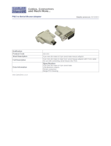
2.3 A Typical Application
Figure 2-1 shows a very basic but typical application for the ServSwitch Multi (a Base Unit, in this case):
Figure 2-1. A three-computer, three-user-station ServSwitch Multi system.
* All monitors are multisync types because each shared monitor in a ServSwitch Multi system must be capable of
synchronizing with the video output of any attached computer.
† If you use Macintosh console equipment in a multiplatform system, you must use a PC-style serial mouse. This is
because, although the remapping functions of the ServSwitch Multi (see Section 8.4) make it possible for a Mac
keyboard attached to the Switch to emulate the functions of a PC or Sun keyboard, at the time of this writing there is
no way for a one-button Apple mouse attached to the Switch to emulate a mouse with more buttons.
Secondary
consoles
(user
stations)
Have access to
each attached
computer
Wall
plug
Local console (user station)
This primary console not only has access to
each attached computer, but also has control
over the Base Unit’s front-panel pushbuttons.
Mac† keyboard, mouse, multisync*
monitor, and external modem
Sun keyboard, mouse, multisync* monitor,
microphone, speakers, and serial printer
PC keyboard, mouse, multisync*
monitor, microphone, and headphones
Channel A:
IBM compatible PC
Channel C: Sun
workstation or server
Channel B: Macintosh
compatible computer
ServSwitch
Multi Base
Unit (rear
panel
shown)

CHAPTER 2: Introduction
17
2.4 Limitations and Restrictions
Keep these things in mind as you plan, design, install, and operate your ServSwitch Multi system:
• The ServSwitch Multi supports these models of mice:
– Microsoft serial or PS/2 mouse (including the IntelliMouse
®
);
– Microsoft OEM style serial mouse;
– Logitech
®
Mouseman
®
and Trackman
®
;
– IBM PS/2 style mouse;
– Kensington
®
PS/2 or ADB mouse;
– Mouse Systems (PC Mouse);
– Sun Microsystems Laser mouse; and
– Apple ADB mouse.
Other manufacturers’ mice generally operate with the ServSwitch Multi, but we cannot guarantee that any
given mouse will. If you experience problems using an untested mouse, contact Black Box Technical
Support with the manufacturer and model number of the mouse.
• Monitors at all user stations must be capable of synchronizing with any attached computer’s video rate. If
you are unsure whether your monitors have multisync capability, consult the monitor documentation or
contact your dealer.
• Use only Black Box supplied cable with the ServSwitch Multi. Poorly constructed or miswired cabling will
diminish video quality and could possibly damage your equipment.
• The ServSwitch Multi supports all externally powered speakers that use 3.5-mm miniplugs. We recommend
that you use powered speakers with the ServSwitch Multi for best performance.
• Use “mono” microphones with 3.5-mm miniplugs with the ServSwitch Multi. Powered microphones are not
recommended; if a computer channel is selected that supplies power to the microphones, the microphone
volume might be muted on that channel.
• The ServSwitch Multi’s CPU and User Cards autosense EIA/TIA RS-232 serial devices using any data format
and hardware, software (“inband”), or no flow control: hardware flow control up to 9600 bps, software or
no flow control up to 115,200 bps. The ServSwitch Multi’s Serial Control Cards support user-configurable
RS-232 connections from 1200 to 19,200 bps using 7 or 8 data bits; even, odd, or no parity; 1 or 2 stop bits;
and hardware, software, or no flow control.

SERVSWITCH™ MULTI
18
2.5 Safety Precautions
To avoid potential video or keyboard problems with the ServSwitch Multi, take these precautions:
• If the site has 3-phase AC power, make sure that each ServSwitch Multi and all of the computers and
monitors attached to it are on the same phase. For best results, they should be on the same circuit.
• Use adapter cables supplied by Black Box only.
To avoid potentially fatal shock and possible damage to equipment, take these precautions as well:
• Do not use 2-wire extension cords with the ServSwitch Multi.
• Test the AC outlets that the monitors and computers are plugged into for proper polarity and grounding.
• Plug the ServSwitch Multi and all monitors and computers into grounded outlets only. If you are plugging
the Switch and any attached equipment into a backup power supply (BPS) or uninterruptible power supply
(UPS), you should plug the Switch, monitor, and computers into the same supply if at all possible.
• With the exception of adding or removing Cards, you should power down the ServSwitch Multi and all
attached computers before you service the unit in any way. Always disconnect the power cord from the unit
when you power it down.
Note that the AC inlet is the ServSwitch Multi’s main disconnect.
All ServSwitch Multi models are rated for input voltages of 110 to 240 VAC and input frequency of 50 or
60 Hz. The ServSwitch Multi Hub (KV170RA) is rated for total load-balanced input current of 7 amps: When
only one power supply is functioning, it will provide all 7 amps, but when both supplies are working, they will
share the load. All other ServSwitch Multi models are rated for 1.6 amps.
2.6 The System and Its Components
2.6.1 THE COMPLETE SERVSWITCH MULTI PACKAGE AND OTHER COMPONENTS YOU’LL NEED
• Each ServSwitch Multi Base Unit (KV150A-R2) and ServSwitch Multi MX (KV155A) is shipped from the
factory with an embedded local-console module, a power cord, and a copy of this manual.
• Each ServSwitch Multi EXP (Expansion Chassis, KV160A-R2) and ServSwitch Multi SB (KV162RA) comes
from the factory with a power cord and a copy of this manual.
• Each ServSwitch Multi Hub (KV170RA) comes from the factory with its two power-supply modules and two
fan assemblies uninstalled. It also comes with two power cords and a copy of this manual.
If you didn’t receive everything, or if anything arrived damaged, call Black Box right away.
In addition, you’ll need other components to build a complete ServSwitch Multi system (contact Black Box
Technical Support if you’re not sure what you’ll need for your application). With the Base Unit, MX, EXP, or
SB, you’ll need some combination of:
• One or more Autosensing CPU-Interface Cards (KV2000C) and one or more 8-foot (2.4-m), 20-foot
(6.1-m), or 30-foot (9.1-m) CPU (Server) Cables to attach servers or other computers to the Switch.

CHAPTER 2: Introduction
19
• To attach user stations to the Switch, 1-foot (0.3-m), 10-foot (3-m), or 20-foot (6.1-m) User Cables attached
to additional Universal User-Interface Cards (KV2500C) or User-Interface Cards with On-Screen Display
(KV2550C-R2) as necessary—up to a maximum of:
– one into an MX whose Local Console you’re using;
– two into an MX whose Local Console you’re not using;
– three into a Base Unit whose Local Console you’re using;
– four into an EXP or into a Base Unit whose Local Console you’re not using; or
– eight into an SB.
• In a cascaded multi-Switch system, expansion cables as necessary to connect Switches to each other: KV1600
for 10-foot [3-m] regular expansion cable, KV1600100 for 100-ft. (30.5-m) regular cable, or EYN737MS-MM
for Category 5 expansion cable.
• In order to attach terminals, hubs, routers, or other serially accessed control devices to the Switch, you’ll
need one Serial Control Card (KV1609C) and four Category 5 patch cables (EVMSL05) for every four such
machines, plus a single Management Card (KV1608C-R2) and a DB9 null-modem cable (EYN257H) to
hook up a PC to manage the Serial Control Cards with.
With the Hub you’ll need:
• Several Transmit Modules (KV1701C) and Receive Modules (KV1702C), plus Category 5 expansion cables
(EYN737MS-MM) to connect the Hub to the other Switches in your system.
2.6.2 R
ACKMOUNTING THE SERVSWITCH MULTI (OPTIONAL)
The ServSwitch Multi SB and ServSwitch Multi Hub can be mounted in a standard 19" equipment rack without
any additional hardware. Just match the holes in the protruding ends of the Switch’s faceplate to an
appropriate set of matching holes on your equipment rack, then fasten the assembly to the rack using your own
screws, bolts, or cage nuts (not included).
If you want to mount a ServSwitch Multi Base Unit, you’ll need a ServSwitch Multi Rackmounting Kit
(RMK19L); to mount a ServSwitch Multi EXP, you’ll need the RMK19LE Kit. See Appendix F for instructions
on how to rackmount either of these models.
The ServSwitch Multi MX is not designed to be rackmounted.
/