Page is loading ...

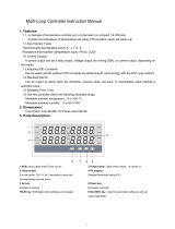
Temperature Controller
FZ110/FZ
4
00/FZ900
Instruction Manual
[Host Communication]
IMR03A07-E4
RKC INSTRUMENT INC.
®

All Rights Reserved, Copyright 2016, RKC INSTRUMENT INC.
NOTICE
Windows is a trademark of Microsoft Corporation.
Modbus is a registered trademark of Schneider Electric.
Company names and product names used in this manual are the trademarks or registered trademarks
of the respective companies.
This manual assumes that the reader has a fundamental knowledge of the principles of
electricity, process control, computer technology and communications.
The figures, diagrams and numeric values used in this manual are only for explanation
purpose.
RKC is not responsible for any damage or injury that is caused as a result of using this
instrument, instrument failure or indirect damage.
RKC is not responsible for any damage and/or injury resulting from the use of instruments
made by imitating this instrument.
Periodic maintenance is required for safe and proper operation of this instrument. Some
components have a limited service life, or characteristics that change over time.
Every effort has been made to ensure accuracy of all information contained herein. RKC
makes no warranty, expressed or implied, with respect to the accuracy of the information.
The information in this manual is subject to change without prior notice.
No portion of this document may be reprinted, modified, copied, transmitted, digitized, stored,
processed or retrieved through any mechanical, electronic, optical or other means without
prior written approval from RKC.

IMR03A07-E4 i-1
Safety Precautions
Pictorial Symbols (safety symbols)
Various pictorial symbols are used in this manual to ensure safe use of the product, to protect
you and other people from harm, and to prevent damage to property. The symbols are
described below.
Be sure you thoroughly understand the meaning of the symbols before reading this manual.
:
This mark indicates precautions that must be
taken if there is danger of electric shock, fire,
etc., which could result in loss of life or injury.
:
This mark indicates that if these precautions
and operating procedures are not taken,
damage to the instrument may result.
: This mark indicates that all precautions
should be taken for safe usage.
To prevent injury to persons, damage to the instrument and the equipment, a
suitable external protection device shall be required.
All wiring must be completed before power is turned on to prevent electric
shock, fire or damage to the instrument and the equipment.
This instrument must be used in accordance with the specifications to prevent
fire or damage to the instrument and the equipment.
This instrument is not intended for use in locations subject to flammable or
explosive gases.
Do not touch high-voltage connections such as power supply terminals, etc. to
avoid electric shock.
RKC is not responsible if this instrument is repaired, modified or
disassembled by other than factory-approved personnel. Malfunction may
occur and warranty is void under these conditions.

IMR03A07-E4
i-2
● This product is intended for use with industrial machines, test and measuring equipment.
(It is not designed for use with medical equipment and nuclear energy plant.)
● This is a Class A instrument. In a domestic environment, this instrument may cause radio
interference, in which case the user may be required to take additional measures.
● This instrument is protected from electric shock by reinforced insulation. Provide reinforced
insulation between the wire for the input signal and the wires for instrument power supply,
source of power and loads.
● Be sure to provide an appropriate surge control circuit respectively for the following:
- If input/output or signal lines within the building are longer than 30 meters.
- If input/output or signal lines leave the building, regardless the length.
● This instrument is designed for installation in an enclosed instrumentation panel. All
high-voltage connections such as power supply terminals must be enclosed in the
instrumentation panel to avoid electric shock to operating personnel.
● All precautions described in this manual should be taken to avoid damage to the instrument or
equipment.
● If the equipment is used in a manner not specified by the manufacturer, the protection provided
by the equipment may be impaired.
● All wiring must be in accordance with local codes and regulations.
● To prevent instrument damage as a result of failure, protect the power line and the input/output
lines from high currents with a suitable overcurrent protection device with adequate breaking
capacity such as a fuse, circuit breaker, etc.
● A malfunction in this product may occasionally make control operations impossible or prevent
alarm outputs, resulting in a possible hazard. Take appropriate measures in the end use to
prevent hazards in the event of malfunction.
● Prevent metal fragments or lead wire scraps from falling inside instrument case to avoid electric
shock, fire or malfunction.
● Tighten each terminal screw to the specified torque found in the manual to avoid electric shock,
fire or malfunction.
● For proper operation of this instrument, provide adequate ventilation for heat dissipation.
● Do not connect wires to unused terminals as this will interfere with proper operation of the
instrument.
● Turn off the power supply before cleaning the instrument.
● Do not use a volatile solvent such as paint thinner to clean the instrument. Deformation or
discoloration may occur. Use a soft, dry cloth to remove stains from the instrument.
● To avoid damage to the instrument display, do not rub with an abrasive material or push the
front panel with a hard object.
When disposing of each part used for this instrument, always follows the procedure for
disposing of industrial wastes stipulated by the respective local community.
For Proper Disposal

IMR03A07-E4
i-3
Symbols
Pictorial Symbols (safety symbols)
: This mark indicates important information on installation, handling
and operating procedures.
: This mark indicates supplemental information on installation,
handling and operating procedures.
: This mark indicates where additional information may be located.
Character Symbols
11-segment character
0 1 2 3 4 5 6 7 8 9
Minus Period
0 1 2 3 4 5 6 7 8 9 - .
A B (b) C c D (d) E F G H I J K
A b C c D E F G H I J K
L M N n O (o) P Q R S T t U
L M N n o P Q R S T t U
u V W X Y Z
Degree
/
Prime
*
(Asterisk)
→
u V W X Y Z
@
/ ` Š ‹
7-segment character
0 1 2 3 4 5 6 7 8 9
Minus Period
0 1 2 3 4 5 6 7 8 9 - .
A B (b) C c D (d) E F G H I J K
A b C c D EFGHI J K
L M N (n) O (o) P Q R S T t U u
L M n o P QRSTt U u
V W X Y Z
Degree
/
Prime
*
(Asterisk)
V W X Y Z
@
`Š

IMR03A07-E4
i-4
Abbreviation symbols
These abbreviations are used in this manual:
Abbreviation
symbols
Name
Abbreviation
symbols
Name
PV Measured value TC (input) Thermocouple (input)
SV Set value RTD (input) Resistance temperature detector (input)
MV Manipulated output value V (input) Voltage (input)
AT Autotuning I (input) Current (input)
ST Startup tuning HBA (1, 2) Heater break alarm (1, 2)
OUT (1 to 3) Output (1 to 3) CT (1, 2) Current transformer (1, 2)
DI (1 to 6) Digital input (1 to 6) LBA Control loop break alarm
DO (1 to 4) Digital output (1 to 4) LBD LBA deadband
FBR Feedback resistance

IMR03A07-E4
i-5
Document Configuration
There are seven manuals pertaining to this product. Please be sure to read all manuals specific to your
application requirements.
The following manuals can be downloaded from the official RKC website:
http://www.rkcinst.com/english/manual_load.htm.
Manual
Manual
Number
Remarks
FZ110/FZ400/FZ900 Installation Manual IMR03A01-E This manual is enclosed with instrument.
This manual explains the mounting and wiring.
FZ110/FZ400/FZ900 Quick Operation Manual IMR03A02-E This manual is enclosed with instrument.
This manual explains the basic key operation, mode
menu, and data setting.
FZ110/FZ400/FZ900 Parameter List IMR03A03-E This manual is enclosed with instrument.
This list is a compilation of the parameter data of
each mode.
FZ110/FZ400/FZ900 Instruction Manual
[Part 1: Hardware]
IMR03A04-E This manual describes installation, wiring,
troubleshooting and product specification.
FZ110/FZ400/FZ900 Instruction Manual
[Part 2: Parameters/Functions]
IMR03A05-E Parameters:
This manual describes how to switch the operation
modes and parameters, the range of parameters, and
initialization/automatic conversion associated with
the change of settings.
Functions:
This manual describes how to
set up and each
function.
FZ110/FZ400/FZ900 Instruction Manual
[Host Communication]
IMR03A07-E4
This manual you are reading now.
This manual explains RKC communication
protocol (ANSI X3.28-1976) and Modbus relating
to communication parameters setting.
FZ110/FZ400/FZ900 Instruction Manual
[PLC Communication]
IMR03A08-E This manual describes how to set up the instrument
for communication with a programmable controller
(PLC).
Read this manual carefully before operating the instrument. Please place the manual in a
convenient location for easy reference.

IMR03A07-E4
i-6
About This Manual
This manual consists of 8 chapters and an appendix. If you are looking for topics concerning the host
communication, you may be able to find one in the following table.
What do you want to do?
See the following section for
more details
I want to know the features of the host communication 1 OUTLINE
I want to know how to connect to the host computer 2. WIRING
I want to know how to connect to the loader communication device 2. WIRING
I want to know how to set up the communication parameters 3. PARAMETER SETTING
I want to know the content of RKC communication protocol 4. RKC COMMUNICATION
PROTOCOL
I want to know the content of Modbus protocol 5. MODBUS PROTOCOL
I want to know how to use Modbus data mapping 5. MODBUS PROTOCOL
I want to know how to use Memory area data 5. MODBUS PROTOCOL
I want to check the data map structure 6. COMMUNICATION DATA
LIST
I want to know how to read the table 6. COMMUNICATION DATA
LIST
I want to check RKC communication/Modbus (double word) [data
register address, data attribute, data range and factory set values]
6. COMMUNICATION DATA
LIST
I want to check Modbus data register address (single word) 6. COMMUNICATION DATA
LIST
I want to check the communication data register address equivalent
to the FB series
6. COMMUNICATION DATA
LIST
I want to know how to cope with errors 7. TROUBLESHOOTING
I want to know the specification of the host communication 8. SPECIFICATIONS
I want to see the table of ASCII/JIS 7-bit code A. APPENDIX

IMR03A07-E4
i-7
Contents
Page
NOTICE
Safety Precautions ............................................................................................................................... i-1
Pictorial Symbols (safety symbols) .............................................................................................. i-1
WARNING ....................................................................................................................................... i-1
CAUTION ........................................................................................................................................ i-2
For Proper Disposal .............................................................................................................................. i-2
Symbols ................................................................................................................................................ i-3
Pictorial Symbols (safety symbols) .............................................................................................. i-3
Character Symbols ...................................................................................................................... i-3
Abbreviation symbols ................................................................................................................... i-4
Document Configuration ....................................................................................................................... i-5
About This Manual ................................................................................................................................ i-6
1. OUTLINE ............................................................................ 1-1
Chapter 1 describes the host communication of FZ110/400/900.
2. WIRING .............................................................................. 2-1
Chapter 2 describes how to connect to the host computer.
2.1 Wiring Cautions ............................................................................................ 2-2
2.2 Wiring for Host Communication .................................................................... 2-3
2.2.1 Connection to the RS-485 port of FZ110/400/900 .......................................................... 2-3
Communication terminal number and signal details ........................................................ 2-3
Connection to the RS-485 port of the host computer (master) ........................................ 2-4
Connection to the RS-232C port of the host computer (master) ..................................... 2-5
Connection to the USB of the host computer (master) .................................................... 2-6
2.2.2 Connection to the RS-422A port of FZ400/900 ............................................................... 2-7
Communication terminal number and signal details ........................................................ 2-7
Connection to the RS-422A port of the host computer (master) ..................................... 2-8
Connection to the RS-232C port of the host computer (master) ..................................... 2-9
Connection to the USB of the host computer (master) .................................................. 2-10
2.3 Connections for Loader Communication .................................................... 2-11
Position of loader communication connector ................................................................. 2-11
Wiring method ................................................................................................................ 2-11

IMR03A07-E4
i-8
Page
3. PARAMETER SETTING .................................................... 3-1
Chapter 3 describes how to set up parameters necessary for the host communication.
3.1 Setting of Communication Parameter ........................................................... 3-2
3.1.1 Description of each parameter ........................................................................................ 3-2
3.1.2 Setting procedure ............................................................................................................ 3-4
3.2 Selection of Communication Data Type ....................................................... 3-5
3.2.1 Communication data type ............................................................................................... 3-5
3.2.2 Description of each parameter ........................................................................................ 3-6
3.2.3 Setting procedure ............................................................................................................ 3-7
3.3 Communication Requirements ..................................................................... 3-8
Processing times during data send/receive ..................................................................... 3-8
RS-485 (2-wire system) send/receive timing (RKC communication) ............................... 3-9
Fail-safe ........................................................................................................................... 3-9
4. RKC COMMUNICATION PROTOCOL .............................. 4-1
Chapter 4 describes the RKC communication protocol.
4.1 Polling ........................................................................................................... 4-2
4.1.1 Polling procedures .......................................................................................................... 4-3
4.1.2 Polling procedure example .............................................................................................. 4-7
4.2 Selecting ....................................................................................................... 4-8
4.2.1 Selecting procedures ...................................................................................................... 4-8
4.2.2 Selecting procedure example ........................................................................................ 4-12
5. MODBUS PROTOCOL ...................................................... 5-1
Chapter 5 describes the Modbus protocol.
5.1 Message Format ........................................................................................... 5-2
5.2 Function Code .............................................................................................. 5-3
5.3 Communication Mode ................................................................................... 5-3
5.4 Slave Responses .......................................................................................... 5-4
5.5 Calculating CRC-16 ...................................................................................... 5-5
5.6 Register Read and Write .............................................................................. 5-8
Read holding registers [03H] ........................................................................................... 5-8
Preset single register [06H] ............................................................................................ 5-10
Diagnostics (Loopback test) [08H] ................................................................................. 5-11
Preset multiple registers (Write multiple registers) [10H]............................................... 5-12
5.7 Caution for Handling Communication Data ................................................ 5-13
5.8 How to Use Modbus Data Mapping ............................................................ 5-15
5.9 How to Use Memory Area Data .................................................................. 5-18
5.9.1 Read and write of memory area data ............................................................................ 5-18
5.9.2 Control area transfer ..................................................................................................... 5-21

IMR03A07-E4
i-9
Page
6. COMMUNICATION DATA LIST ........................................ 6-1
Chapter 6 describes the communication data.
6.1 Data Map Structure ...................................................................................... 6-2
6.1.1 Structure of RKC Communication/Modbus (Double Word) data map ........................... 6-2
6.1.2 Structure of Modbus (Single Word) data map ............................................................... 6-4
6.2 How to Read the Table ................................................................................ 6-5
Data map of RKC communication identifiers/Modbus double word ................................ 6-5
Data map of Modbus single word .................................................................................... 6-7
Data map of FB series equivalent communication .......................................................... 6-8
6.3 RKC Communication/Modbus (Double Word) Data ...................................... 6-9
6.3.1 Communication data [RKC communication identifier/ Modbus double word] ................. 6-9
6.3.2 Memory area data (Direct designation method) [Modbus double word] ....................... 6-76
6.3.3 Data mapping address [Modbus double word] ........................................................... 6-101
6.4 Modbus (Single Word) Data ..................................................................... 6-106
6.4.1 FZ110/400/900 communication data [Modbus single word] ...................................... 6-106
6.4.2 Memory area data (Direct designation method) [Modbus single word] ..................... 6-119
6.4.3 Data mapping address [Modbus single word] ............................................................ 6-131
6.4.4 FB series equivalent communication data [Modbus single word] .............................. 6-135
6.4.5 Memory area data equivalent to the FB series (Area designation method)
[Modbus single word] ................................................................................................. 6-149
7. TROUBLESHOOTING ....................................................... 7-1
Chapter 7 describes how to cope with errors during the communication.
7.1 RKC Communication .................................................................................... 7-3
7.2 Modbus ........................................................................................................ 7-4
8. SPECIFICATIONS ............................................................. 8-1
Chapter 8 describes the specification of the host communication.
8.1 RKC Communication .................................................................................... 8-2
8.2 Modbus ........................................................................................................ 8-3
8.3 Loader Communication ................................................................................ 8-4
A. APPENDIX........................................................................ A-1
A.1 ASCII 7-Bit Code Table ............................................................................... A-2
A.2 Communication Data Equivalent to Our REX-D Series ............................... A-3
A.3 Communication Data Equivalent to Our REX-F400/700/900....................... A-4
INDEX .................................................................................... B-1

IMR03A07-E4
i-10
MEMO

OUTLINE
IMR03A07-E4 1-1
This chapter describes the host communication of FZ110/400/900.

1. OUTLINE
1-2 IMR03A07-E4
The communication function makes it possible to monitor and set the data of the Temperature Controller
FZ110/400/900 from a host computer. The FZ110/400/900 interfaces with the host computer via Modbus or
RKC communication (ANSI X3.28-1976 subcategories 2.5 and A4) protocols. Communication function is
available only when optional communication function has been specified at the time of ordering.
In addition, the controller FZ110/400/900 is equipped standard with a loader communication connector.
Therefore, loader communication is possible. For reference purposes, the Modbus protocol identifies the host
computer as master, the controller as slave.
Host communication (RKC communication, Modbus) [Optional]
Communication interface: RS-485
RS-422A (FZ400/900 only)
Multi-drop connection (Communication interface: RS-485)
One host computer (master) can communicate with up to 31 FZ110/400/900s.
Communication data type
There are such data as shown below for the communication with the computer.
Communication data type can be selected at Input data type (INdT).
For the Input data type, refer to 3.2 Selection of Communication Data Type (P. 3-5).
RKC communication
7 digits data, Communication data of FZ110/400/900
6 digits data, Communication data of FZ110/400/900
6 digits data, Communication data equivalent to our REX-D series (RKC communication identifiers
are compatible)
The RKC communication identifiers for the REX-D series can be used to handle the
communication data of the FZ110/400/900 corresponding to the REX-D series.
If there is no relevant communication data on the FZ110/400/900, dummy data is used.
Modbus
Double word, Communication data of FZ110/400/900
Single word, Communication data of FZ110/400/900
Single word, Communication data equivalent to our FB series (Modbus register addresses are
compatible)
The Modbus register addresses for the FB series can be used to handle the
communication data of the FZ110/400/900 corresponding to the FB series.
If there is no relevant communication data on the FZ110/400/900, the data is handled as
unused data.
Host computer (master)
RKC communication or Modbus
[Communication interface: RS-485, RS-422A (FZ400/900 only)
FZ110/400/900 (slave) maximum connections: Up to 31 controllers

1. OUTLINE
IMR03A07-E4
1-3
Loader communication
Loader communication allows FZ110/400/900 data to be set from a personal computer.
By saving the data that was set using our Communication Tool PROTEM2 to a computer, the data can be
transferred to other FZ110/400/900s, allowing setup to be accomplished much more quickly than when
the data is set in each FZ110/400/900 using the front panel keys.
RKC USB communication converter COM-K2 (sold separately) is required for the loader communication.
The Loader port is only for parameter setup. Not used for data logging during operation.
Loader communication can be used on a FZ110/400/900 even when the Communication function
(optional) is not installed.
The loader communication corresponds to the RKC communication protocol “Based on ANSI
X3.28-1976 subcategories 2.5 and A4.”
A previous version of COM-K (version 1) can be also used. However, if communication tool
PROTEM2 is used using a COM-K, the PROTEM2 will not be supported by Windows 8 or later.
PLC communication
The PLC communication function makes it possible to monitor and set the data of the Temperature
Controller FZ110/400/900 from a programmable controller (PLC).
The FZ110/400/900 can be connected to the programmable controller (PLC) without using any program.
This manual describes the host communication (RKC communication and Modbus).
For the PLC communication, refer to FZ110/FZ400/FZ900 Instruction Manual
[PLC Communication] (IMR03A08-E).
Personal computer FZ110/400/900
Maximum connections: 1 controller
USB communication converter
COM-K2

1. OUTLINE
IMR03A07-E4
1-4
Communication Tool PROTEM2
PROTEM2 is an integrated configuration support software to manage parameter setting and measured
values of our controllers and consists of the following tools:
・Base Tool:
Used to set/verify controller parameters.
・Recipe Tool:
Used to conduct overall management of parameter set values of our controllers (storing to a
computer and transfer to other controllers.)
・Logger Tool:
Used to visualize various data with graphs and perform data logging in CSV format.
・Configuration Tool:
Used for configure virtual controllers for the Base Tool. *
* PROTEM2 handles controllers as the unit of a project.
Controllers connected to the project are called “Virtual controllers.”
PROTEM2 requires Microsoft.NET Framework 4 to be installed on the computer.
PROTEM2 can be used with RKC standard protocol and Modbus protocol.
PROTEM2 can also be used for loader communication and a host communication.
The PROTEM2 can be downloaded from the official RKC website:
http://www.rkcinst.com

WIRING
IMR03A07-E4 2-1
This chapter describes how to connect to the host computer.
2.1 Wiring Cautions ................................................................................ 2-2
2.2 Wiring for Host Communication ....................................................... 2-3
2.2.1 Connection to the RS-485 port of FZ110/400/900 ............................... 2-3
Communication terminal number and signal details .............................. 2-3
Connection to the RS-485 port of the host computer (master) .............. 2-4
Connection to the RS-232C port of the host computer (master) ............ 2-5
Connection to the USB of the host computer (master) .......................... 2-6
2.2.2 Connection to the RS-422A port of FZ400/900 ................................... 2-7
Communication terminal number and signal details .............................. 2-7
Connection to the RS-422A port of the host computer (master) ............ 2-8
Connection to the RS-232C port of the host computer (master) ............ 2-9
Connection to the USB of the host computer (master) ........................ 2-10
2.3 Connections for Loader Communication ........................................ 2-11
Position of loader communication connector ....................................... 2-11
Wiring method ...................................................................................... 2-11

2. WIRING
2-2 IMR03A07-E4
2.1 Wiring Cautions
To avoid noise induction, keep communication wire away from instrument power line, load lines and
power lines of other electric equipment.
Use the solderless terminal appropriate to the screw size.
Screw size: M3×7 (with 5.8×5.8 square washer)
Recommended tightening torque:
0.4 N・m
[4 kgf・cm]
Applicable wire: Solid/twisted wire of 0.25 to 1.65 mm
2
Specified dimension:
Refer to Fig. at the right
Specified solderless terminal:
Manufactured by J.S.T MFG CO., LTD.
Circular terminal with isolation V1.25-MS3
Make sure that during field wiring parts of conductors cannot come into contact with adjacent conductive
parts.
If solderless terminal lugs other than the recommended dimensions are used, terminal screws may not be
tightened. In that case, bend each solderless terminal lug before wiring. If the terminal screw is forcibly
tightened, it may be damaged.
Up to two solderless terminal lugs can be connected to one terminal screw. The requirements of
reinforced insulation can be still complied with in this condition. When actually doing this, place one
solderless terminal lug over the other as illustrated below.
To prevent electric shock or instrument failure, do not turn on the power until all wiring
is completed. Make sure that the wiring is correct before applying power to the
instrument.
5.9 (MAX)
3.2 (MIN)
5.6 mm
(2.8 mm)
5.9 mm (MAX)
3.2 mm (MIN)
5.6 mm
Two solderless terminals are used overlapped.
(FZ110 is used in the example shown, but restrictions for crossover
wiring are the same for FZ400/900.)
Top view
(FZ110)
Panel
Solderless
terminal lug
Terminal
screw

2. WIRING
IMR03A07-E4
2-3
2.2 Wiring for Host Communication
Host communication is used for a connection to a host computer via RS-485 or RS-422A.
2.2.1 Connection to the RS-485 port of FZ110/400/900
Communication terminal number and signal details
RS-485
FZ110
terminal No.
FZ400/900
terminal No.
Symbol Signal name
16 34 SG
Signal ground
17 35 T/R (A)
Send data/Receive data
18 36 T/R (B)
Send data/Receive data
25
26
27
28
29
30
31
32
33
34
35
36
1
2
3
4
5
6
7
8
9
10
11
12
13
14
15
16
17
18
19
20
21
22
23
24
FZ400/900
rear terminals
Communication (Optional)
RS-485
SG
34
T/R (A)
T/R (B)
35
36
Communication (Optional)
RS-485
SG
16
T/R (A)
T/R (B)
17
18
13
14
15
16
17
18
1
2
3
4
5
6
7
8
9
10
11
12
FZ110
rear terminals

2. WIRING
IMR03A07-E4
2-4
Connection to the RS-485 port of the host computer (master)
Wiring example
The communication cable and termination resistor(s) must be provided by the customer.
Host computer (Master)
RS-485
Paired
wire
Shielded twisted
pair wire
FZ110/400/900 (Slave)
*R
*R
16 (34)
T/R (B)
T/R (A)
17 (35)
18 (36)
SG
T/R (B)
T/R (A)
SG
*R: Termination resistors (Example: 120 1/2 W)
If communication errors occur frequently due to
the operation environment or the communication
distance, connect termination resistors.
()
()
FZ110/400/900 (Slave)
16 (34)
T/R (B)
T/R (A)
17 (35)
18 (36)
SG
()
()
()
()
Maximum connections: Up to 31 FZ110/400/900s
/