Page is loading ...

Super four
Installation and
servicing instructions
GB

CONTENTS
1 DESCRIPTION OF THE BOILER . . . . . . . . . . . . . . . . . . . . . . . . . . . . . . . . . . . . . . . . . . . . . . . . . . . . . . . . . . . . . . . . . . . . . . . . . . . . . . 1
2 INSTALLATION . . . . . . . . . . . . . . . . . . . . . . . . . . . . . . . . . . . . . . . . . . . . . . . . . . . . . . . . . . . . . . . . . . . . . . . . . . . . . . . . . . . . . . . . . . . . . 3
3 CHARACTERISTICS . . . . . . . . . . . . . . . . . . . . . . . . . . . . . . . . . . . . . . . . . . . . . . . . . . . . . . . . . . . . . . . . . . . . . . . . . . . . . . . . . . . . . . . . 7
4 USE AND MAINTENANCE . . . . . . . . . . . . . . . . . . . . . . . . . . . . . . . . . . . . . . . . . . . . . . . . . . . . . . . . . . . . . . . . . . . . . . . . . . . . . . . . . . 10
IMPORTANT
When carrying out commissioning of the boiler, you are recommended to perform the following checks:
– Make sure that the system is charged with water and is thoroughly vented.
– Make sure that any shutoff valves are open.
– Check that the pipe for expulsion of products of combustion is unobstructed and has been properly installed.
– Make sure that the boiler is set for operation for the type of gas supplied.
– Open the gas tap and check the soundness of the connections, including that of the burner.
–
Purge the system, bleeding off the air present in the gas pipe by operating the air relief valve on the gas
valve inlet.
– Make sure that the electrical connections have been made correctly and that the earth wire is connected to a
good earthing system.
– Check whether the circulating pumps are obstructed; if so, clear them out.
– Check that there are no liquids or inflammable materials in the immediate vicinity of the boiler.
Please refer to commissioning instructions for filling in the log book
Note: All CORGI registered installers carry a CORGI ID Card.
You can check your installer is CORGI Registered by calling 01256 372300

1
1.3 TECHNICAL FEATURES
1 DESCRIPTION OF BOILER
1.1 INTRODUCTION
“SUPER FOUR” boilers are gas-fired
thermal appliances for C.H. and D.H.W.
production.
They are defined as “sealed-room”
appliances because the air necessary
for combustion is drawn in from outsi-
de the ambiences in which they are
installed.
They come complete with all safety and
control devices and appurtenances
required by current standards, and
are built in compliance with the
European Directives pr EN 483 - pr EN
625. These appliances can be fired by
natural gas and L.P.G. (G30 - G31).
The instructions given in this manual
are provided for the installer to ensure
proper installation and perfect opera-
tion of the appliance.
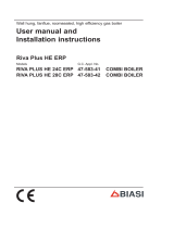
1.2 DIMENSIONS
M C.H. flow 22 mm
R C.H. return 22 mm
E D.H.W. inlet 15 mm
G Gas connection 1/2 in
U D.H.W. outlet 15 mm
CS Concentric flue duct ø 60/100
Fig. 1
* The gas consumptions refer to the calorific value at standard conditions at 15°C - 1013 mbar
SUPER FOUR
Heat output
Maximum kW 28.5
Minimum kW 15.1
Heat input
Maximum kW 31.6
Minimum kW 18.0
Boiler water capacity l 4.7
Electric power W150
Maximum water head bar 3
Boiler expansion vessel
Capacity l 8
Pre-loading pressure bar 1
D.H.W. production
D.H.W flow rate (EN 625) l/min 15.3
D.H.W. continuous flow rate with ∆t 30°C l/h 815
Tank recovery time from 40 to 70°C min 5
Tank capacity l 50
Maximum water head D.H.W. system bar 7
D.H.W. expansion vessel l 2.5
Weight kg 115
Category II2H3+
Type C12 -C32-C52
SUPER FOUR
Smokes temperature °C 140
Smokes flow gr/s 21.9
Main gas nozzles
Quantity n° 15
Natural gas ø mm 1.30
G30 - G31 ø mm 0.77
Gas consumption *
Natural gas m
3
s/h 3.34
L.P.G. (G30) kg/h 2.49
L.P.G. (G31) kg/h 2.45
Burner gas pressure
Natural gas mbar 11
L.P.G. (G30) mbar 28
L.P.G. (G31) mbar 35
Gas supply pressure
Natural gas mbar 20
L.P.G. (G30) mbar 30
L.P.G. (G31) mbar 37
Flue duct maximum length
concentric ø 60/100 m 3

2
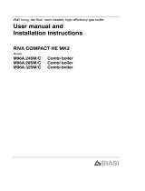
KEY
1 Sealed chamber
2 Smoke pressure switch
3Fan
4 Water-gas exchanger
5 Boiler expansion vessel
6 System safety valve
7 Hydrometer
8 Modulating gas valve
9 100°C safety stat
12 Non-return valve
13 Boiler unit circulating pump
14 Manual bleed valve
15 Heating sensor (SM)
16 Water pressure switch
17 System circulating pump
18 D.H.W. sensor (SS)
19 Storage boiler unit
20 Boiler unit drain cock
21 D.H.W. expansion vessel
23 Magnesium anode
24 Air relief valve
25 Boiler unit safety valve
26 Frost stat
27 D.H.W. isolation valve
28 Gas cock
29 C.H. return isolation valve
30 C.H. flow isolation valve
1.4 FUNCTIONAL DIAGRAM
Fig. 2
1.5 INSIDE FRONT VIEW
Fig. 3
KEY
1 Boiler expansion vessel
2 Burner
3 D.H.W. sensor (SS)
4 100°C safety stat
5 Venturi
6Fan
7 Smoke pressure switch
8 Positive pressure intake
9 Negative pressure intake
10 Heating sensor (SM)
11 Modulating gas valve
12 System circulating pump
13 Storage boiler unit
14 Non-return valve
15 Boiler unit circulating pump
16 D.H.W. expansion vessel
17 Boiler unit drain cock

3
Installation is to be understood as per-
manent and must be carried out exclu-
sively by specialized and qualified firms,
in compliance with all the instructions
and provisions set out in this manual.
2.1 BOILER ROOM
Since the “SUPER FOUR” version boilers
do not exceed the limit of 35 kW, they
may be installed, without any constraints
regarding location or supply of air for
combustion, in any domestic ambience.
2.2 CONNECTING UP SYSTEM
Before proceeding to connecting up the
boiler, you are recommended to get
water to circulate in the piping in order
to eliminate any foreign bodies that
might be detrimental to the operating
efficiency of the appliance. When
making the hydraulic connections, make
sure that the dimensions indicated in
fig. 1 are respected. The discharge
pipe of the two safety valves (6-7 fig.
13) must be connected to a collector
funnel for channelling away any
discharge in the case of the safety val-
ves going into action. The gas connec-
tion must be made using seamless
steel tubes (Mannesmann type).
NOTE: To connect the gas cock to the
boiler, undo the union and the washer
(2 fig. 13).
Where the piping has to pass through
walls, a suitable insulating sleeve must
be provided. When sizing gas piping,
from the meter to the boiler, take into
account both the volume flow rates
(consumption) in m
3
/h and the relative
density of the gas in question. The sec-
tions of the piping making up the system
must be such as to guarantee a supply
of gas sufficient to cover the maximum
demand, limiting pressure loss between
the gas meter and any apparatus being
used to not greater than:
–
1.0 mbar for family II gases (natural gas);
– 2.0 mbar for family III gases (L.P.G.).
An adhesive data plate is stuck on the
inside of the panel; it contains all the
technical data identifying the boiler and
the type of gas for which the boiler is
arranged.
2.2.1 Filter on gas pipe
The gas valve used on the “SUPER
FOUR” boilers is fitted standard with an
inlet filter, which, however, is not able to
entrap all the impurities in the gas or in
gas mains pipes. To prevent malfunctio-
ning of the valve, or in certain cases
even cutting out of the safety device
with which the valve is equipped, install
an adequate filter on the gas pipe.
2.3 CHARACTERISTICS
OF FEEDWATER
Where the mains water has a hard-
ness of more than 20-25° Fr, the
feedwater must be suitably softened
both for the domestic water circuit
and for the central heating circuit, so
as to prevent formation of boiler scale
due to lime deposits, since this could
lead to a reduced heat exchange.
It should be remembered that even
small encrustations of just a few milli-
metres thick, on account of their low
thermal conductivity, cause a conside-
rable overheating of the walls of the
boiler with serious consequences.
IT IS ABSOLUTELY ESSENTIAL THAT
THE WATER USED FOR THE CENTRAL
HEATING SYSTEM SHOULD BE TREA-
TED IN THE FOLLOWING CASES:
– very extensive system (with high con-
tents of feedwater);
– frequent addition of makeup water
into the system.
Should it be necessary to empty the
system either partially or totally, the
subsequent refilling should be carried
out using suitably treated water.
NOTE: If the water pressure from the
mains is above 4 bar, a pressure
reducing valve should be fitted.
2.4 SYSTEM FILLING
With the system cold, the charge pres-
sure must be between 1 and 1.2 bar.
During system filling, you are recom-
mended to keep the switching knob tur-
ned OFF. The system should be filled
slowly, so that any air bubbles can be
bled off through the air relief valves.
To facilitate this operation, set the
groove on the release screw of the
non-return valves horizontally.
In the event of the pressure in the
system dropping below 0.6 bar during
operation (owing to elimination of
gases dissolved in the water), the boi-
ler will shut off automatically, and the
red warning light (11 fig. 11) will start
flashing. Bring the water filling pressu-
re to 1-1.2 bar, which can be read on
the hydrometer. Once the correct
pressure has been restored, the war-
ning light will turn off automatically and
the boiler will start operating again.
Should the pressure have risen well
above the limit envisaged, release the
excess pressure by opening the relief
valve on any radiator.
2.5 COAXIAL AIR INLET-FLUE
OUTLET ASSEMBLY
The air inlet-flue outlet assembly is sup-
plied upon demand in a separate kit
(Code 8084802). It includes:
–
coaxial duct ø 60/100 L. 840, with
wind-proof (anti-blowback) head already
fixed to the flue discharge duct;
– pipe bend ø 60/100 with fixing
screws;
– fixing clamp;
– rubber ring nut for external closing;
– sponge-rubber gasket.
The aluminium ring nut for internal clo-
sing with locking screws is supplied
separately in the package containing
the boiler.
2.5.1 Assembly of coaxial duct kit
In order to assembly follow closely
what is indicated in fig. 4.
– Make a hole in the wall sufficiently
large to allow for insertion of a ø 130
mm PVC pipe of the same length as
the thickness of the wall it has to
pass through. Then fix the PVC pipe
in place using cement mortar.
WARNING: When cutting the pipe,
remember that the ø 60 mm flue
discharge tube must be approx. 25
mm longer than the air intake tube.
– Before sliding the pipe into the hole
made in the wall, insert the rubber
sealing ring (E) into its seat made in
the tube.
– Push the tube outwards until the
gasket comes out. Pull the pipe
inwards bringing the ring to rest on
the wall.
– Slide the inner ring (D) and the metal
collar (I) onto the pipe.
– Push the flue discharge duct (F) fully
home in the bend and fasten the
metal collar (I) in position, tightening
the two fixing screws.
– Fasten the duct (C) by tightening the
two screws (H) on the aluminium
ring nut (D).
2 INSTALLATION

NOTE: The air intake-flue outlet
assembly must slope gently
downwards to prevent rain water
getting into the boiler.
2.5.2 Coaxial air intake-flue outlet
assembly accessories
In addition to the coaxial duct kit, also
the following can be supplied on reque-
st (fig. 5):
– extension ø 60/100 L. 855 (Code
8084800);
– supplementary 90° pipe elbow ø
60/100 (Code 8085600);
– vertical extension ø 60/100 L. 590
(Code 8086900).
– vertical connection ø 60/100 (Code
8086901).
NOTE: With the pipe bend supplied in
the kit, the maximum length of piping
should not exceed 3 m. In the case
where the supplementary elbow (4
fig. 5) is used, the total length of
piping can reach a maximum of 1.6 m.
When the vertical extension (3 fig. 5)
is used, the terminal part of the pipe
must always come out horizontally.
2.5.3 Positioning outlet terminals
The outlet terminals for forced-draught
appliances may be located in the exter-
nal perimeter walls of the building.
To provide some indications of possible
solutions,
Table 1
gives the minimum
distances to be observed, with refe-
rence to the type of building shown in
fig. 6.
4
Fig. 6
KEY
A Elbow flange
B Junction collar
C Outer duct
D Aluminium ring
E Rubber sealing ring
F Inner duct c/w terminal
H Fixing screw
I Protective metal collar
J Inner “O” ring
Fig. 4
KEY
1a-b Coaxial duct kit
2 Extension ø 60/100 L. 855
3 Vertical extension
4 90° supplementary elbow
5 Vertical connection
Fig. 5
TABLE 1
Siting of teminal Minimum spacing
mm in
A Directly below an openable window
air vent or any other ventilation opening 300 12
B Below guttering, drain pipes or soil pipes 75 3
C/D
Below eaves, balconies or carport roof 200 8
E From vertical drain pipes or soil pipes 75 3
F From internal or external corners 300 12
G Above adjacent ground, roof or balcony level 300 12
H From a surface facing the terminal 600 24
I From a terminal facing the terminal 1,200 48
J From an opening in the carport
(eg door, window into dwelling) 1,200 48
K Vertically from a terminal on the same wall 1,500 60
L Horizontally from a terminal on the same wall 300 12
M Adjacent to opening 300 12

5
2.5.4 Coaxial duct outlet on roof
The accessories to be used for this
type of installation and some of the
connecting systems that may be adop-
ted are illustrated in fig. 8.
When assembling the accessories,
remember that the roof discharge ter-
minal (L. 1,280 mm) cannot be shorte-
ned and that the articulated joint of the
roof tile allows roof pitches of between
25° and 45°. The tile is a plane roofing
tile and comes fitted with a shaped and
folded lead panel (dimensions 160 x
440) for adaptation to the roof. When
joining the tile to the terminal, use the
collar inserted on the latter, fastening
it in position with the three self-tapping
screws provided (fig. 7).
When positioning the roof tile, make
sure to leave a distance of not less
than 600 mm from the discharge top
of the roof-outlet terminal.
It is possible to insert up to a maxi-
mum of three extensions and reach a
maximum rectilinear distance of 3.7
m. Should it be necessary to make
two changes of direction in the pipe
development, the maximum length of
the pipe must not exceed 2 m.
2.6 ELECTRICAL CONNECTION
The electric power supply to the boiler
must be 230 V - 50 Hz single-phase
through a fused main switch, with at
least 3 mm spacing between contacts.
You are recommended to install a room
temperature thermostat to ensure bet-
ter regulation of temperature and
comfort of indoor ambience. This ther-
mostat must be Class II, in compliance
with the Standard EN 60730.1.
NOTE: SIME declines all responsibility
for injury or damage to persons, ani-
mals or things, resulting from impro-
per earthing of the appliance.
2.6.1 Electric switchboard
The electric switchboard consists of a
fused electronic card for controlling
temperature and flame modulation,
with a built-in trimmer for adjusting
heating power output and warning leds
that indicate some of the possible failu-
re that may cause irregular operation
or failure of the boiler (fig. 9).
KEY
1 Pipe elbow ø 60/100 code 8085603
2 Extension ø 60/100 code 8084800
3 Articulated-joint roof tile code 8091300
4 Roof outlet terminal
ø 60/100 code 8091200
5
Supplementary 90° elbow
ø 60/100
code 8085600
Fig. 8
KEY
1 Tile with articulated joint
2 Lead panel
3 Collar
4 Self-tapping screw
Fig. 7
KEY
1 Room-temp. thermostat socket
2 EMC filter
3 4-pole wired connector
4 6-pole wired connector
5 5-pole wired connector
6 FM 31 control box
7 Electronic card
8 8-pole wired connector
9 3-pole wired connector
10 Switching knob
11 Time programmer
Fig. 9

6
KEY
L Phase
N Neutral
PF Smoke pressure switch
F1 Fuse (T 50 mA)
F2 Fuse (T 1,6 A)
VFan
EV1 1
st
gas valve
EV2 2
nd
gas valve
A Control box FM 31
EA Ignition electrode
ER Sensing electrode
TS 100°C safety stat
TA Room stat
M Modulating coil
PA Water pressure switch
PI C.H. circulating pump
PB D.H.W. circulating pump
SM Heating sensor (blue)
SS D.H.W. sensor (red)
C Four-way switch
FA EMC filter
TC Time clock
TAG Fro st st at
NOTE: The room stat must be connected
to the terminals 40-41 of the three-pole
terminal block after removing the link.
2.6.2 Wiring diagram
Fig. 10

3.1 ELECTRONIC CARD
The electronic card of “SUPER FOUR”
boilers is equipped with control leds
which signal some of the possible failu-
res that can cause an irregular and/or
improper operation of the appliance.
The leds are arranged on the card as
indicated in fig. 11 and marked with the
following wordings:
–
“RICHIESTA” (5 fig. 11): green led ali-
ght on demand for D.H.W. or heating.
– “LD1” (8 fig. 11): red led alight to
indicate FM 31 programmer is
blocked.
– “LD2” (11 fig. 11): green led alight
when electric power is reaching the
card. Red led flashing to indicate
absence of water.
3.1.1 Devices present
on electronic card
The electronic card of the “SUPER
FOUR” boilers is equipped with the fol-
lowing devices:
– “MET-GPL” connector (10 fig. 11)
The “L.P.G.-MET” connector link must
be inserted on the type of gas for
which the boiler is arranged.
– “POT. ACC.” trimmer (7 fig. 11)
The electronic card has an “IGNI-
TION PRESSURE” trimmer for
varying the pressure level upon igni-
tion (STEP) of the gas valve.
According to the type of gas for
which the boiler is arranged, the
trimmer must be regulated so as to
obtain a pressure of approx. 3.5
mbar at the burner for natural gas
and 7 mbar for L.P.G. (G30 - G31).
To increase pressure, turn the
trimmer clockwise; to reduce pres-
sure, turn the trimmer counter-
clockwise.
Fig. 12 gives an indication of where
to set the trimmer according to the
type of gas used.
Before regulating the trimmer,
make sure that the “L.P.G.-MET”
connector (10 fig. 11) is connected
to the type of gas for which the boi-
ler is arranged.
NOTE: After setting the pressure
level upon ignition (STEP) according
to the type of gas, check that the
pressure for heating is still at the
value previously set.
– “ANN. RIT.” connector (3 fig. 11)
In the heating phase, the electronic
card is programmed to include a
burner technical delay interval of
approx. 2 minutes, which occurs
both at system cold starting and at
subsequent re-ignitions.
The aim is to overcome the problem
of repeated ignition and turning off
with very short time intervals
7
KEY
1 Fuse (T 50 mA)
2 Fuse (T 1,6 A)
3 “Cancel delays” connector
5 “Request for ignition” led
6 “Smoke thermostat” led (not used)
7 “Ignition pressure” trimmer
8 “Equipment lock-out” led
9 “Heating output” trimmer
10 “L.P.G.-MET” connector
11 “Electric supply/no water warning” led
Fig. 11
3 CHARACTERISTICS
METANO
MAX. - G.P.L.MIN.
Fig. 12

8
between. This could occur in particu-
lar in systems presenting high head
losses. At each restart after the
period of slow ignition, the boiler will
set itself for about 1 minute at the
minimum modulation pressure, and
will then move to the heating pres-
sure value set.
When the connecting link is inser-
ted, both the programmed technical
pause and the period of operation at
minimum pressure in the start-up
phase will be cancelled.
In this case, the times elapsing
between turning off and subsequent
re-ignition will depend on a tempera-
ture difference of 8°C detected by
the SM sensor.
NOTE: It is essential that the opera-
tions described above be carried out
by authorized technical staff.
3.2 TEMPERATURE SENSORS
The “SUPER FOUR” boilers are equip-
ped with sensors for detecting tempe-
rature:
– C.H. sensor, located on the outlet
pipe of the primary exchanger (SM)
–
D.H.W. sensor located on the hot
water storage boiler unit (SS).
The sensors are NTC mod. ST03
ones and are interchangeable.
Table 2
shows the resistance values
that are obtained on the sensors as
the temperature varies.
NOTE: Should the SM sensor be
shorted, the boiler will not operate
either for central heating or for hot
water; should, instead, the SS sensor
be shorted, the boiler will operate
only for central heating.
3.3 ELECTRONIC IGNITION
The “SUPER FOUR” version boilers
are of the type with automatic ignition
(without pilot burner).
They are therefore equipped with FM
31 electronic control and protection (6
fig. 9). Ignition and flame detection is
controlled by two electrodes located
on the burner.
These guarantee maximum safety
with intervention times, for accidental
switching off or gas failure, of within
one second.
3.3.1 Operating cycle
Turn the switching knob located on
the control board to either SUMMER
or WINTER to check for presence of
voltage supply (green warning lamp
lights up).
The boiler is now ready to start
working upon demand for heating or
drawing off of domestic water; a
discharge current is sent to the igni-
tion electrode through the FM 31
programmer, and the gas valve opens
at the same time.
Burner ignition normally takes place
within 2 or 3 seconds starting from
the moment when the discharge cur-
rent reaches the ignition electrode.
However, it is possible for ignition failu-
res to occur, with consequent activa-
tion of signal indicating that the equip-
ment has “locked out”.
Failures may be due to one of the fol-
lowing causes:
– Gas failure
The appliance runs through the cycle
normally sending electric power to
the ignition electrode.
The electrode continues spark
discharge for a maximum of 10 sec.
If the burner does not ignite, the
equipment “locks out”.
This may occur upon first ignition or
after long periods of boiler lay-off
when there is air in the pipes. It may
be caused by the gas tap being clo-
sed or by one of the valve coils
having a break in the winding, so that
the valve cannot open.
– Ignition electrode fails to spark
In the boiler, only the gas to the bur-
ner is seen to open. After 10 sec.
the equipment “locks out”.
This may be due to a break in the
wire of the electrode, or the wire not
properly fastened to the equipment
electric terminal; or else, the tran-
sformer has burnt out.
– No detection of flame
The continuous spark discharge of
the electrode is noted starting from
ignition, even though the burner is lit.
After 10 seconds have elapsed, the
sparks cease, the burner goes out,
and the warning light indicating
equipment “lock-out” lights up.
This occurs when the position of line
and neutral has not been respected
on the terminal block.
There is a break in the wire to the
sensing electrode, or the electrode
itself is touching earth; the electrode
is worn out and needs replacing.
When there is a sudden voltage failure,
the burner shuts out immediately;
when power supply returns, the boiler
will start up again automatically.
3.4 SMOKE PRESSURE
SWITCH
The smoke pressure switch is located
inside the sealed- room (7 fig. 3).
To gain access to the pressure switch,
first you must release the four hinges
and remove the fixing screw of the
front wall.
A Venturi tube system, fastened inside
the fan unit and connected to the pres-
sure switch by means of two silicone
pipes, ensures start-up of the burner
only when the fan is operating.
Impurities and possible formations of
condensate, which are more likely in
cold periods of the year, could cause
the pressure switch not to function
and the boiler to fail to start. The pres-
sure switch is set in the factory at the
optimal values of 8-9 mm H
2
O.
This is able to guarantee operation of
the boiler even with air intake and flue
outlet pipes have the maximum limit of
length allowed.
3.5 WATER FAILURE
SAFETY DEVICE
The boiler is equipped with a water
pressure switch (8 fig. 13) set at 0.6
bar, which goes into action, blocking
boiler operation, whenever the pressu-
re inside the boiler is less than the cali-
bration value.
When the pressure switch trips, a
red warning lamp starts flashing (11
fig. 11). To restore burner operation,
turn the charge cock and bring the
pressure back to a value between 1
and 1.2 bar.
Temperature °C Resistance Ω
20 12,000
30 8,300
35 6,900
40 5,800
45 4,900
50 4,100
55 3,500
60 3,000
70 2,200
80 1,700
TABLE 2

9
3.6 SYSTEM AVAILABLE HEAD
500 1000 1500
0
100
200
300
400
500
Portata l/h
Prevalenza residua (mbar)
MURELLE BN - AVANT BF
RESIDUAL HEAD mbar
FLOW RATE l/h
Fig. 14
Fig. 13
KEY
1 Gas cock
2 Union
3 C.H. return cock
4 C.H. flow cock
5 D.H.W. inlet cock
6 D.H.W. safety valve
7 System safety valve
8 Water pressure switch
9Frost stat

10
SIME SUPPORT
THE BENCHMARK INITIATIVE
All relevant sections of the logbook
must be filled in at the time of installa-
tion and thereafter service informa-
tion on the back page of the logbook.
Commissioning of the boiler is not
complete until the logbook is filled in.
4.1 PRODUCTION OF D.H.W.
The production of hot water for
washing purposes is guaranteed by a
porcelain enamelled steel boiler unit
provided with an inspection flange for
checks and cleaning, and a magnesium
anode protecting the boiler unit.
The magnesium anode must be
inspected periodically. Should it be
worn out, replace it; otherwise, the
boiler unit warranty will be rendered
null and void.
The temperature of D.H.W. is fixed and
is set on the electronic card.
NOTE: Should the boiler unit fail to
produce D.H.W., turn it off and make
sure that the system has been suita-
bly purged by operating the manual
air valves.
4.2 GAS VALVE
The “SUPER FOUR” boilers come
equipped standard with a SIT 837 TAN-
DEM gas valve (fig. 15).
4.3 GAS VALVE ADJUSTMENT
Since all “SUPER FOUR” versions are
flame-modulation boilers, they have the
gas valve set at two pressure values:
maximum and minimum. According to
the type of gas burnt, these corre-
spond to the values given in
Table 3
.
Calibration of the gas pressures at the
maximum and minimum values is done
by SIME in the factory. Consequently,
they should not be altered. Only when
you switch from one type of gas supply
(methane) to another (butane or pro-
pane), it is permitted to alter the ope-
rating pressure.
It is essential that this operation be
carried out exclusively by authorized
technical staff.
When the gas pressures are to be
reset, this must be done following a set
order: first the maximum pressure and
then the minimum.
4.3.1 Maximum pressure
adjustment
To set the maximum pressure, pro-
ceed as follows (fig. 16):
– connect a pressure column or pres-
sure gauge to the pressure intake
downstream of the gas valve;
– remove the plastic cap (1);
– set the switching knob to SUMMER
and open the D.H.W. tap at a high
flow rate;
–
with the boiler lit, using a ø 10 span-
ner, turn the nut (3) to arrive at the
maximum pressure value given in
Table 3
: to reduce the pressure, turn
the nut counterclockwise; to increase
the pressure, turn it clockwise:
– turn off and re-ignite the boiler a
number of times, keeping the D.H.W.
tap open all the time, and check that
the pressure corresponds to the
values given in
Table 3
.
4.3.2 Minimum pressure
adjustment
To set the minimum pressure, proceed
as follows (fig. 16):
–
again use a pressure column or a pres-
sure gauge to check the pressure;
– disconnect supply to the modulator;
– set the switching knob to SUMMER
and open the hot water tap;
– with the boiler lit, blocking the nut
(3), turn the screw (2) to arrive at
the minimum pressure value given in
Table 3
: to reduce the pressure,
turn the screw counterclockwise; to
increase the pressure, turn it
clockwise;
– turn off and re-ignite the boiler a
number of times, keeping the D.H.W.
tap open all the time, and check that
the pressure corresponds to the
values given in
Table 3
;
– restore electric power to the modu-
lator and replace plastic cap (1).
4.4 ADJUSTMENT OF HEAT
OUTPUT FOR HEATING
To adjust boiler heat output for heating
purposes, i.e., modifying the setting
made at the factory, which is approxi-
mately 18,5 kW, use a screwdriver to
adjust the heating heat output trimmer
(2 fig. 17). To increase working pressu-
re, turn the trimmer clockwise
(towards the + sign); to reduce pres-
sure, turn the trimmer counterclockwi-
se (towards the – sign).
In this way the boiler will start opera-
ting at the preset pressure value, and
when the temperature approaches the
value chosen on the heating knob,
4 USE AND MAINTENANCE
Fig. 15
TABLE 3
KEY
1 Modulator
2 Solenoid valves EV1 - EV2
3 Pressure intake downstream
4 Pressure intake upstream
5 VENT plug
Type of gas Burner max. pressure Burner min. pressure
mbar mbar
Natural gas - G20 11 2
L.P.G. - G30 28 7
L.P.G. - G31 35 7
KEY
1 Plastic cap
2 Minimum pressure
adjusting screw
3 Maximum pressure
adjusting nut
Fig. 16

11
according to a sequence already set
on the electronic adjustment card, will
start modulating automatically, thus
supplying the system with the actual
power required. When the temperatu-
re read by the sensor corresponds to
the value selected on the potentiome-
ter, the boiler will already be at mini-
mum burner flame.
At this point, the potentiometer will
cause the burner to go out. To facilita-
te the operations of adjusting heating
output, see the pressure/heat output
diagrams for natural gas or L.P.G.,
shown in figs. 18 - 18/a - 18/b.
4.5 CONVERSION
TO DIFFERENT GAS
To convert to L.P.G. (G30) or L.P.G.
(G31), first replace the main nozzles.
Proceed as follows (fig. 19):
– close the gas tap;
– disassemble the front panel of the
outer casing;
– remove the closing plate of the sea-
led chamber, loosening off the four
hinges and the two fixing screws;
– remove the front closing plate of the
combustion chamber, unscrewing
the four screws;
– slide out the burner unit (4);
– unscrew the screws (5) and replace
the main nozzles (3) located on the
burner manifold (1), inserting the
copper washer (2). Use a ø 7 span-
ner to perform this operation;
– reassemble all the parts, proceeding
in reverse order;
– remove the “L.P.G.-MET” connector
link on the card (10 fig. 11) and set it
on “L.P.G.”. To change the slow igni-
tion value, regulate the “IGNITION
PRESSURE” trimmer (7 fig. 11), so
as to obtain a pressure to the bur-
ner of approx. 7 mbar.
– To set the values of maximum and
minimum gas pressure, follow the
11
10
9
8
7
6
5
4
3
2
1
8,1 (7.000) 11,6 (10.000) 17,4 (15.000) 23,2 (20.000)
POTENZA TERMICA kW (kcal/h)
PRESSIONE UGELLO mbar
29,1 (25.000)
25
20
15
10
8,1 (7.000) 11,6 (10.000) 17,4 (15.000) 23,2 (20.000)
POTENZA TERMICA kW (kcal/h)
PRESSIONE UGELLO mbar
30
5
29,1 (25.000)
Fig. 18/a
KEY
1 Heating potentiometer
2 Trimmer
Fig. 17
NOZZLE PRESSURE (mbar)NOZZLE PRESSURE (mbar)
HEAT OUTPUT kW (kcal/h)
HEAT OUTPUT kW (kcal/h)
25
20
15
10
8,1 (7.000) 11,6 (10.000) 17,4 (15.000) 23,2 (20.000)
POTENZA TERMICA kW (kcal/h)
PRESSIONE UGELLO mbar
30
35
5
29,1 (25.000)
Fig. 18/b
Pressure/heat output diagram for natural gas
Pressure/heat output diagram for L.P.G. (G30)
Pressure/heat output diagram for L.P.G. (G31)
Fig. 18
NOZZLE PRESSURE (mbar)
HEAT OUTPUT kW (kcal/h)

12
instructions given in section 4.3. The
gas feed pressure must under no
circumstances exceed 50 mbar.
– after have ultimated the conversion
of the boiler, please stick onto the
casing panel the plate showing the
relevant feeding gas which is inclu-
ded into the conversion kit.
NOTE: After assembling all the gas
connections, a test for gas tightness
must be carried out using soapy
water or special products. DO NOT
USE NAKED FLAMES.
4.6 DISASSEMBLY OF
EXPANSION VESSEL
To disassemble the boiler expansion
vessel, proceed as follows:
– make sure that the water has been
emptied out of the boiler;
– unscrew the connection connecting
the expansion vessel to the boiler
and the two self-tapping screws that
fasten the system to the bracket.
NOTE: Before refilling the system,
make sure that the expansion vessel
is pre-loaded at 1 bar pressure.
4.7 CLEANING AND
MAINTENANCE
At the end of each heating season, it is
essential to have the boiler thoroughly
checked and cleaned out. Proceed as
follows:
–
turn the switching knob to OFF to stop
electric power reaching the boiler;
– close the gas feed cock;
– disassemble the outer casing;
– remove the smoke chamber,
unscrewing the screws that fasten it
to the combustion chamber;
–
disassemble the gas burner-manifold
unit, as described in Section 4.5;
– to clean the burners, blow in a jet of
air, so as to remove any dust parti-
cles that may have accumulated;
–
clean the heat exchanger, removing
any dust or residue from combustion;
– when cleaning the heat exchanger or
the burners, chemical products or
steel brushes MUST NOT BE USED;
– make sure that the tops of the bur-
ners with the holes are free from
encrustations;
– reassemble the items removed from
the boiler, making sure to follow the
correct sequence;
– check the chimney to make sure
that the flue is clean;
– check operation of the equipment
and of the main burner.
Preventive maintenance and checking
of efficient operation of equipment
and safety devices must be carried
out at the end of each season.
4.8 FAULT FINDING
Main burner does not start either to
draw off D.H.W. or heating.
– Check operation of smoke pressure
switch.
– Check, and if necessary replace,
smoke pressure switch.
– Replace electronic card.
– Check if SM is interrupted.
Fan turns but burner does not start.
– Check whether connection tubes of
smoke pressure switch PF are
obstructed and, if necessary, clean
away impurities or condensate.
– Smoke pressure switch PF needs
recalibrating or, better still, replacing
with a new factory-calibrated one.
Fan fails to turn.
– Check whether electric power is rea-
ching the terminals of the activator
motor.
– Motor winding is burnt out; replace.
– Replace electronic card.
Main burner fails to modulate both in
D.H.W. phase and in heating phase.
– Modulator M has a break in winding;
replace.
– Electronic card is faulty; replace.
Boiler makes noises and a sizzling
sound.
– Check whether circulating pumps
are obstructed; if necessary, clear
them out.
– Unclog impeller of circulating pump,
clearing away any impurities or sedi-
ments.
–
Circulating pump is burnt out; replace.
– Check boiler output is adequate for
actual needs of heating system.
Boiler safety valve keeps going into
action.
– Check whether system cold charge
pressure is too high; keep to recom-
mended values.
– Check whether safety valve is out of
calibration; if necessary, replace.
– Check pre-loading pressure of
expansion vessel.
– Replace expansion vessel if faulty.
Radiators fail to heat up in winter.
– Knob is set to SUMMER. Turn it to
WINTER.
– Room stat TA is set too low or needs
replacing because faulty.
– Electrical connections of room stat
TA are wrong.
Radiators warm up also in summer.
– Check for right setting of knob.
– Check no impurities are present in
the non-return valve seat.
– Non-return valve is faulty; replace.
– Install non-return valve on system
return pipe.
Main burner burns badly: flames too
high, too yellow.
– Check that pressure of gas reaching
burner is regular.
– Check burners are clean.
Water from boiling unit isn’t suffi-
ciently hot.
– Air is still present at the top of the
boiler. Purge off through air relief
valve.
– Reduce hot-water drawing-off rate.
Smell of unburnt gases.
– Check boiler is properly clean.
– Check draught is sufficient.
– Check whether gas consumption is
too high.
Boiler operates but does not increa-
se temperature.
– Check whether gas consumption is
not lower than it should be.
– Check boiler is clean.
– Check boiler is sized in proportion to
system.
KEY
1 Burner manifold
2 Copper washer ø 6.1
3 Nozzle M6
4 Burner unit
5 Screw TCB M4 x 6
Fig. 19


Cod. 6258908A - Documentation Dpt.
Sime Ltd
Unit D2 Enterprise Way, Bradford Road, Idle, Bradford BD10 8EW
Tel. 0870 9911114 - Fax 0870 9911115
www.sime.ltd.uk - e-mail: [email protected]
/