Page is loading ...

HORIZON HZ-24
INSTALLATION AND OPERATIONINSTALLATION AND OPERATION
MANUALMANUAL
November 16, 2000 P/N 7610-002-32-24
Visit Jackson on the Internet at:
www.jacksonmsc.com
HIGH TEMP SANITIZING
UNDERCOUNTER DISHMACHINE

MANUFACTURERS WARRANTY
ONE YEAR LIMITED PARTS & LABOR WARRANTY
ALL NEW JACKSON DISHWASHERS ARE WARRANTED TO THE ORIGINAL PURCHASER TO BE FREE FROM
DEFECTS IN MATERIAL OR WORKMANSHIP, UNDER NORMAL USE AND OPERATION FOR A PERIOD OF (1) ONE
YEAR FROM THE DATE OF PURCHASE, BUT IN NO EVENT TO EXCEED (18) EIGHTEEN MONTHS FROM THE
DATE OF SHIPMENT FROM THE FACTORY.
Jackson MSC agrees under this warranty to repair or replace, at its discretion, any original part which fails under normal use due to faulty
material or workmanship during the warranty period, providing the equipment has been unaltered, and has been properly installed, main-
tained and operated in accordance with the applicable factory instruction manual furnished with the machine and the failure is reported to
the authorized service agency within the warranty period. This includes the use of factory specified genuine replacement parts, purchased
directly from a Jackson authorized parts distributor or service agency. Use of generic replacement parts may create a hazard and void
warranty certification.
The labor to repair or replace such failed part will be paid by Jackson MSC, within the continental United States, Hawaii and Canada, dur-
ing the warranty period provided a Jackson MSC authorized service agency, or those having prior authorization from the factory, performs
the service. Any repair work by persons other than a Jackson MSC authorized service agency is the sole responsibility of the customer.
Labor coverage is limited to regular hourly rates, overtime premiums and emergency service charges will not be paid by Jackson MSC.
Accessory components not installed by the factory carry a (1) one year parts warranty only. Accessory components such as table limit
switches, pressure regulators, pre rinse units, etc. that are shipped with the unit and installed at the site are included. Labor to repair or
replace these components is not covered by Jackson MSC.
This warranty is void if failure is a direct result from shipping, handling, fire, water, accident, misuse, acts of god, attempted repair by unau-
thorized persons, improper installation, if serial number has been removed or altered, or if unit is used for purpose other than it was origi-
nally intended.
TRAVEL LIMITATIONS
Jackson MSC limits warranty travel time to (2) two hours and mileage to (100) one hundred miles. Jackson MSC will not pay for travel
time and mileage that exceeds this, or any fees such as those for air or boat travel without prior authorization.
WARRANTY REGISTRATION CARD
The warranty registration card supplied with the machine must be returned to Jackson MSC within 30 days to validate the warranty.
REPLACEMENT PARTS WARRANTY
Jackson replacement parts are warranted for a period of 90 days from the date of installation or 180 days from the date of shipment from
the factory, which ever occurs first.
PRODUCT CHANGES AND UPDATES
Jackson MSC reserves the right to make changes in design and specification of any equipment as engineering or necessity requires.
THIS IS THE ENTIRE AND ONLY WARRANTY OF JACKSON MSC. JACKSON’S LIABILITY ON ANY CLAIM OF ANY KIND, INCLUD-
ING NEGLIGENCE, WITH RESPECT TO THE GOODS OR SERVICES COVERED HEREUNDER, SHALL IN NO CASE EXCEED THE
PRICE OF THE GOODS OR SERVICES OR PART THEREOF WHICH GIVES RISE TO THE CLAIM.
THERE ARE NO WARRANTIES, EXPRESSED OR IMPLIED, INCLUDING FOR FITNESS OR MERCHANTABILITY, THAT ARE NOT SET
FORTH HEREIN, OR THAT EXTEND BEYOND THE DURATION HEREOF. UNDER NO CIRCUMSTANCES WILL JACKSON MSC BE
LIABLE FOR ANY LOSS OR DAMAGE, DIRECT OR CONSEQUENTIAL, OR FOR THE DAMAGES IN THE NATURE OF PENALTIES,
ARISING OUT OF THE USE OR INABILITY TO USE ANY OF ITS PRODUCTS.
ITEMS NOT COVERED
This warranty does not cover cleaning or deliming of the unit or any component such as, but not limited to, wash arms, rinse arms or strain-
ers at anytime. Nor does it cover adjustments such as, but not limited to timer cams, thermostats or doors, beyond 30 days from the date
of installation. In addition, the warranty will only cover the replacement of wear items such as curtains, drain balls, door guides or gaskets
during the first 30 days after installation. Also, not covered are conditions caused by the use of incorrect (non-Commercial) grade deter-
gents, incorrect water temperature or pressure, or hard water conditions.

GENERAL PAGE
Specifications ............................................................................................... 1
Detail of the Data Plate................................................................................. 2
General Notes Section.................................................................................. 3
INSTALLATION INSTRUCTIONS
Unpacking..................................................................................................... 4
Plumbing Connections.................................................................................. 4
Electrical Connections.................................................................................. 4
Installation Checklist..................................................................................... 5
OPERATION INSTRUCTIONS................................................................................... 6
PROGRAMMING INSTRUCTIONS............................................................................ 9
ELECTRONIC CONTROLLER BOARD REFERENCE............................................. 10
SCHEMATIC
208-230 V, 50-60 Hz, 3 Phase .................................................................... 11
IMPORTANT INFORMATION DATA SHEET............................................................. 12
TABLE OF CONTENTS
i

PERFORMANCE/CAPABILITIES
OPERATING CAPACITY (RACKS/HOUR)
RACKS PER HOUR (NSF RATED) 30
DISHES PER HOUR 600
GLASSES PER HOUR 600
OPERATING CYCLE (SECONDS)
NORMAL CYCLE
WASH TIME 82
DRAIN TIME 10
RINSE TIME 11
TOTAL CYCLE TIME 120
PREWASH/PREHEAT CYCLE
PREWASH TIME 20
DRAIN TIME 10
RINSE TIME 11
WASH TIME 82
DRAIN TIME 10
RINSE TIME 11
TOTAL CYCLE TIME 150
TANK CAPACITY (GALLONS)
WASH TANK (MINIMUM) 1.3
BOOSTER TANK 3
TEMPERATURES
WASH---°F (MINIMUM) 150
RINSE---°F (MINIMUM) 180
ELECTRICAL REQUIREMENTS
WASH PUMP MOTOR HORSEPOWER 3/4
RINSE BOOSTER HEATER ELEMENT 10KW@230V
WATER REQUIREMENTS
INLET TEMPERATURE (Minimum) 140°F
GALLONS PER RACK 1.3
GALLONS PER HOUR(AT 80% CAPACITY) 31.2
WATER LINE SIZE I.P.S. (Minimum) 1/2”
DRAIN LINE SIZE I.P.S. (Minimum) 1”
FLOW PRESSURE P.S.I. (Optimum) 20
MACHINE DIMENSIONS
WIDTH
(
INCLUDING CHEMICAL DISPENSING EQUIPMENT)
30 1/2”
DEPTH 22 5/8”
DEPTH (WITH DOOR OPEN) 39 7/8”
HEIGHT 33 1/4” TO 34 1/4”
CLEARANCE HEIGHT INSIDE 15 1/4”
MINIMUM WALL CLEARANCE 3 1/2”
SPECIFICATIONS FOR THE HORIZON HZ-24
1
VOLTAGE
PHASE
MACHINE
TOTAL
AMPERAGE
REQUIRED
ELECTRICAL
CIRCUIT
208
1
45.3
60 Amp
230
1
49.5
70 Amp
208
3
28.7
40 Amp
230
3
31.1
40 Amp

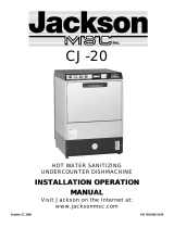
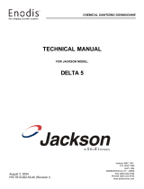
The data plate is located on the right side front corner, directly on the shroud. Under no circumstances should the data plate be
removed from the unit. The data plate is essential in identifying the particular characteristics of your machine and is of great benefit
to installers, operators, and maintenance personnel. In the event the data plate is removed, copy the essential information on the
final page in this manual for reference before installation. Do not use the above data plate to represent your dishmachine. The data
plate above is a generic representation used only to show you where to locate information.
DETAIL OF THE HORIZON HZ-24C DATA PLATE
2
MODEL:
SERIAL #
WASH TEMPERATURE (MIN.)
RINSE TEMPERATURE (MIN.)
WASH CYCLE TIME
RINSE CYCLE TIME
FLOW PRESSURE
INCOMING WATER TEMPERATURE
150° F
180° F
82 SEC
10 SEC
15-25 PSI
110° F
Connect to minimum 50 ampere supply - circuit
protected with maximum 50 A nontime - delay
type fuse or overcurrent protector.
BOOSTER HEATER
WASH MOTOR 3/4 HP
230 VOLT 60 HERTZ 3 PHASE 3 WIRE
27.7 AMP
4.7 AMP
TOTAL LOAD 32.4 AMP
11.0 KW
MANUFACTURER’S
LOGO
MODEL DESIGNATION
(I.E. “HORIZON HZ-24C”)
AMPERAGE LOAD
INFORMATION
MINIMUM PARAMETERS
(SEE NOTE 1)
MANUFACTURERS
ADDRESS INFORMATION
NSF LOGO (SEE NOTE 3)
UL LOGO (SEE NOTE 2)
R

Before connecting, operating, or adjusting any of the dishmachines covered in this manual, please carefully read through the entire
manual to familiarize yourself with the machine and its proper operation. This manual contains important operating, safety, and main-
tenance information concerning your dishmachine. You must follow the instructions and guidelines provided in this manual to ensure
that your warranty remains in effect.
FOR SERVICE PERSONNEL: Jackson MSC Inc. provides technical support for all of the dishmachines detailed in this manual. We
strongly recommend that you refer to this manual before making a call to our technical support staff. Please have this manual with you
when you call so that our staff can refer you, if necessary, to the proper page. Technical support is available from 8:00 a.m. to 5:00 p.m.
(EST), Monday through Friday. Technical support is not available on holidays. Contact technical support toll-free at 1-888-800-5672.
Please remember that technical support is available for service personnel only. Non-service personnel should refer to the list of pro-
vided service agencies in this manual for local service support.
NOTES CONCERNING THE HORIZON HZ-24 DATA PLATE:
NOTE 1: This area of the data plate denotes the minimum parameters that must be met in order for your dishmachine to operate at the
designed level of efficiency. Not meeting the required parameters can result in substandard performance of the dishmachine. Do not
refer to the data plate example in this manual for the parameters of your machine; instead, refer to the data plate affixed to the machine.
If you are unsure of whether or not you are meeting the required minimum parameters, contact your nearest Jackson representative.
NOTE 3: The UL logo on the data plate indicates that this machine is Listed by Underwriters Laboratories Inc. Representative sam-
ples of this product have been evaluated by UL and meet applicable standards and requirements. Dishmachines are evaluated under
UL Standard 921. For more information concerning the UL logo and UL standards in general, you may write to: Underwriters
Laboratories Inc., 333 Pfingsten Road, Northbrook, IL., 70072; or you may visit their website at www.ul.com.
NOTE 3: The NSF logo on the data plate indicates that this machine has been approved to be listed under NSF Standard 3 by NSF
International Inc. All of ECOLAB’S standard 3 approved dishmachines are listed on the NSF website at www.nsf.org. For more infor-
mation concerning NSF International, their testing procedures and their standards in general, you may write to: NSF
International Inc., 789 Dixboro Road, Ann Arbor, MI., 48105.
GENERAL NOTES SECTION
3

VISUAL INSPECTION: Before installing the unit, check the con-
tainer and machine for damage. A damaged container is an indi-
cator that there may be some damage to the machine. If there is
damage to both the container and machine, do not throw away the
container. The dishmachine has been inspected and packed at
the factory and is expected to arrive to you in new, undamaged
condition. However, rough handling by carriers or others may
damage the unit while in transit. If this situation occurs, do not
return the unit to Jackson; contact the carrier and ask them to
inspect the damage to the unit and to complete an inspection
report. You must contact the carrier within 48 hours of receiving
the machine. Also, contact the dealer through which you pur-
chased the unit.
UNPACKING THE DISHMACHINE: Once the machine has been
removed from the container, ensure that there are no missing
parts from the machine. This may not be obvious at first. If it is dis-
covered that an item is missing, contact Jackson immediately to
have the missing item shipped to you.
LEVEL THE DISHMACHINE: Ensure that the unit is level from
side to side and from front to back before making any connec-
tions. The unit comes with adjustable bullet feet, which can be
turned using a pair of pliers or by hand if the unit can be raised
safely. Failure to level the dishmachine may cause premature
wear or decrease washing performance.
PLUMBING THE DISHMACHINE: All plumbing connections must
comply with all applicable local, state, and national plumbing
codes. The plumber is responsible for flushing the incoming water
line prior to connecting it to remove all foreign debris that may get
trapped in the valves or cause an obstruction. Any valves that are
fouled by matter left in the water line and the expenses resulting
are not the responsibility of the manufacturer.
CONNECTING THE DRAIN LINE: The drain for the Horizon HZ-
24 is a pumped (pressure) drain capable of pumping waste water
to a height of 24 inches from the floor to the kitchen’s drain sys-
tem. The dishmachine is supplied with an 8 foot long hose that
extends from the rear side of the machine. There must also be an
air gap between the machine drain line and the floor sink or drain.
If a grease trap is required by code, it should have a flow capaci-
ty of 12 gallons per minute.
WATER SUPPLY CONNECTION: Read the section entitled
“PLUMBING THE DISHMACHINE” above before proceeding.
Connect the flexible hose on the machine to the incoming water
supply line. The water supply is 1/2” pipe size (minimum). It is rec-
ommended that a water shut-off valve be installed between the
main supply and the machine to allow access for service. The
water supply line must be capable of 20 PSI “flow” pressure at the
recommended temperature indicated on the data plate.
In areas where the water pressure fluctuates or is greater than the
recommended pressure, it is recommended that a water pressure
regulator be installed.
Do not confuse static pressure with flow pressure. Static pressure
is the line pressure in a “no flow” condition (all valves and services
are closed). Flow pressure is the pressure in the fill line when the
fill valve is opened during the cycle.
It is also recommended that a shock absorber (not supplied with
the Horizon HZ-24) be installed in the incoming water line.
This prevents line hammer (hydraulic shock), induced by the sole-
noid valve, from causing damage to the equipment.
PLUMBING CHECK: Slowly turn on the water supply to the
machine after connecting the incoming fill line and the drain line.
Check for leaks and repair as required. Leaks must be repaired
prior to placing the machine in operation.
ELECTRICAL POWER CONNECTION: Electrical and grounding
connections must comply with the applicable portions of the
National Electrical Code ANSI/NFPA 70 (latest edition) and/or
other electrical codes.
Disconnect electrical power supply and place a tag at the discon-
nect switch to indicate that you are working on the circuit.
The dishmachine data plate is located on the right side and to the
front of the machine. Refer to the data plate for machine operat-
ing requirements, machine voltage, total amperage load and seri-
al number.
The Horizon model HZ-24 machine is equipped with a 10 foot
long, flexible cord for the incoming power. The end of this cord
must be connected to the corresponding terminals at the circuit
disconnect box by a qualified electrician according to local electri-
cal codes. The colors for the wires within this cable are L1=black,
L2=red, L3=white, Ground=green.
It is recommended that “DE-OX” or another similar anti-oxidation
agent be used on all power connections.
VOLTAGE CHECK: Ensure that the power switch is in the OFF
position and apply power to the dishmachine. Check the incoming
power at the terminal block and ensure it corresponds to the volt-
age listed on the data plate. If not, contact a qualified service
agency to examine the problem. Do not run the dishmachine if the
voltage is too high or low. Shut off the service breaker and mark it
as being for the dishmachine. Advise all proper personnel of any
problems and of the location of the service breaker. Replace the
control box cover and tighten the screws.
INSTALLATION INSTRUCTIONS
4

CHECK OFF THE FOLLOWING ITEMS AS THEY ARE COMPLETED BEFORE PROCEEDING TO OPERATION OF DISHMA-
CHINE.
Has the dishmachine been checked for concealed/hidden damage?
Has the dishmachine and the surrounding area been properly vented in accordance with all applicable codes?
Has the dishmachine been properly leveled?
Has the drain plumbing been installed with an air gap?
Has the service voltage been checked to ensure that it meets the electrical requirements listed on the dishma-
chine’s data plate?
Has the dishmachine been properly grounded?
Has the dishmachine circuit breaker/service breaker been sized correctly, given the dishmachine’s load, and has it
been marked clearly and identified to all pertinent personnel?
Has the incoming water supply been flushed for debris?
Is the hot water supply at the minimum temperature as indicated on the dishmachine data plate?
Is the incoming water supply at 20 PSI?
Is the incoming water supply line at 1/2” minimum?
Are the chemical supplies full and the chemical tubes installed in the proper supply containers?
Have the peristaltic-pumps been primed?
Have the pump intake strainers been installed?
Have the wash arms been installed?
Has the lower rinse arm been installed?
INSTALLATION CHECKLIST
5

OPERATIONAL START-UP & CHECK: Before proceeding with
start-up, verify the following:
1. Open the doors and verify that the wash tank strainer and
pump intake strainer are correctly installed in the sump.
2. Check that the upper rinse nozzles are securely screwed
into their receptacles.
3. Check that the plugs are securely screwed into the ends of
both wash arms and the rinse arm.
4. Check that the wash arms are securely screwed into the
stationary bases and that they rotate freely.
5. Check the levels in all chemical containers and replace if
necessary.
INSTALLATION/INITIAL START-UP PROCEDURE:
1. Turn on Dishmachine
a) Turn on the incoming power to the machine at the
circuit disconnect box. The display will indicate
OFF.
b) Turn on the dishmachine by pressing the PUSH
ON/PUSH OFF button. The red POWER light will
turn on.
2. Load Chemicals and Prime Dispensing Pumps.
a) The display will indicate REFILL CHEMICALS AND
PRIME PUMPS. Place detergent and rinse aid
chemical bottles in the holder. Place the pick-up
tube attached to the red chemical line in the deter-
gent bottle, and the pick-up tube attached to the
clear chemical line in the rinse aid bottle. Prime the
detergent pumps by pressing the DET. PRIME or
RINSE AID PRIME buttons. Hold the button until
a steady flow of chemical is seen exiting the corre-
sponding peristaltic pump. After both pumps are
primed, the display will indicate HEATER DISABLED.
3. Fill Rinse Booster Heater with Water
a) Before the heater element can be energized, the
rinse booster heater must be initially filled with
water. Damage to the heater element will occur if
the element is not submerged in water. To initially
fill the booster heater with water:
i) Press and hold the PROGRAM button.
ii) The display will indicate ENTER CODE. Press
CYCLES, DELIME, ENTER and CYCLES.
iii) The display will indicate PROG DRAIN/FILL.
Repeatedly press the PROGRAM button until
ENGINEERING is displayed. Press ENTER to
enter the engineering mode.
iv) Repeatedly press the PROGRAM button until
PRESS ENTER TO OPEN FILL is displayed.
v) Press and hold the ENTER button to turn on
the incoming water solenoid valve. Continue
holding the button until you hear water enter-
ing the wash chamber through the rinse arms,
then release the button. The rinse booster
heater is now filled with water.
vi) Press the PROGRAM button until PRESS
ENTER TO EXIT is displayed. Press the
ENTER button to exit the engineering mode.
vii) Repeatedly press the PROGRAM button until
EXIT is displayed. Press the ENTER key to
exit the programming mode.
4. Enable Heater Element
a) For the initial start-up only, the heater element must
be enabled. The machine is shipped from the facto-
ry with the heater element disabled. This is done to
ensure that the heater element is not damaged by
energizing the element without the element being
submerged in water. To enable the heater element:
i) Enter the programming mode by pressing and
holding the PROGRAM button.
ii) The display will indicate ENTER CODE. Press
CYCLES, DELIME, ENTER and CYCLES.
iii) The display will indicate PROG DRAIN/FILL.
Repeatedly press the PROGRAM button until
SYSTEM is displayed. Press ENTER to enter
the system programming mode.
iv) Repeatedly press the ENTER button until
HEATER ELEMENT IS DISABLED is dis-
played.
v) Press the DELIME button to change the dis-
play to HEATER ELEMENT IS ENABLED.
vi) Press the PROGRAM key to exit the system
programming mode. You should hear the
heater contactor close.
vii) Repeatedly press the PROGRAM button until
EXIT is displayed. Press the ENTER button
to exit the programming mode.
viii) The display will indicate HEATING WATER.
OPERATING INSTRUCTIONS
6

5. Adjust Dishmachine Fill Level.
a) Once the temperature in the rinse booster heater
has reached its preset value, the incoming water
solenoid valve will open to fill the wash tank with
water (FILLING, the time remaining for the fill, and
the incoming water PRESSURE will be displayed
during the fill sequence).
b) The display will then indicate OPEN DOOR. Open,
and then close the door. The display will indicate
PRESS START KEY TO START CYCLE. Press the
PRESS TO START button.
c) The machine will run a complete cycle. At the end
of the cycle, open the door and observe the water
level in the wash tank. The water level should be at
the top of the sump, just below the bottom of the
wash tank strainer.
d) In the programming section, increase or decrease
the FILL time (PROG DRAIN/FILL menu) as neces-
sary.
6. Adjust Dishmachine Drain Time.
a) Open the door, remove the wash tank strainer, and
observe the sump area immediately after the
machine has completed the drain cycle (just before
the start of the rinse cycle).
b) In the programming section, adjust the DRAIN time
(PROG DRAIN/FILL menu) as necessary. Allow
enough time for the machine to completely drain
before the rinse begins. Avoid making the drain
time too long, which will unnecessarily lengthen the
total cycle time.
7. Adjust Dishmachine Flush Time.
a) The FLUSH will rinse out the detergent residue and
soils in the wash tank before the rinse begins. The
FLUSH time is the time that the drain valve will
remain open at the beginning of the rinse cycle.
Avoid making the flush time too long, which will
increase the water usage per machine cycle.
b) In the programming section, increase or decrease
the FLUSH time (PROG DRAIN/FILL menu) as nec-
essary.
8. Measure and Adjust Chemical Concentrations (see pro-
gramming instructions).
9. Check all water and drain fittings for leaks.
10. Instruct machine operators on proper cleaning and
operating procedures.
GENERAL OPERATION SEQUENCE:
CAUTION: Water must be in the wash tank sump while the wash
pump is running in order to avoid damage to the pump seal.
Close the machine's door. Turn the machine on by pressing the
PUSH ON/PUSH OFF button. The red power light will be illumi-
nated. The display will indicate HEATING WATER while the rinse
water is heated in the booster heater. This heating process may
take several minutes, depending on how long the machine has set
idle.
If the water in the booster heater has not reached the specified
temperature after ten minutes, the booster heater will be turned off
and RINSE TANK ERROR, CALL FOR SERVICE will be dis-
played.
When the water in the booster heater reaches the specified tem-
perature, the machine will automatically fill the wash sump with
water (FILLING, the time remaining for filling, and the incoming
water flow PRESSURE will be indicated on the display). The min-
imum water level should be just at the top of the wash tank sump.
To adjust the water level, see programming instructions.
The display will indicate OPEN DOOR. Open the door and insert
a rack of soiled dishes. The display will indicate CLOSE DOOR.
Close the door and the display will indicate PRESS START KEY
TO START CYCLE. Press the PUSH TO START button to begin
the wash cycle. The wash cycle will begin and the yellow cycle
light will be illuminated.
The machine will not run if either supply of detergent or rinse aid
chemicals is depleted. When this happens, the display will indi-
cate REFILL CHEMICALS AND PRIME PUMPS. Refill or replace
the detergent or rinse aid chemical bottles in the holder. Place the
pick-up tube attached to the red chemical line in the detergent bot-
tle, and the pick-up tube attached to the clear chemical line in the
rinse aid bottle. Prime the detergent pumps by pressing the DET.
PRIME or RINSE AID PRIME buttons. Hold the button until a
steady flow of chemical is seen exiting the corresponding dis-
pensing pump.
The HORIZON HZ-24 dishwasher is equipped with a unique fea-
ture that helps to ensure proper sanitization of the ware during the
wash cycle.
The cycle begins with a prewash sequence. The display indicates
the PREWASH TEMPERATURE. Detergent is dispensed at the
beginning of the prewash sequence. After this prewash sequence,
which is 20 seconds long, if the temperature of the wash tank
water is below 150°F, the machine will automatically drain the
wash water, and refill the wash tank with heated rinse water
before the wash sequence will begin. This usually occurs after the
machine has been setting idle for some time and the wash cham-
ber and the water in the wash tank sump have been allowed to
cool. When the machine is used more often, the wash tank water
will remain above 150°F at the end of the prewash sequence, the
drain and fill steps will be skipped, and the prewash sequence will
immediately begin.
OPERATING INSTRUCTIONS (CONTINUED)
7

During the wash sequence, the display will indicate the WASH
TEMPERATURE. If the wash water was drained at the end of the
prewash sequence, detergent will be dispensed at the beginning
of the wash sequence. At the completion of the wash sequence,
the water in the wash tank sump will be drained (DRAINING will
be displayed). The dishes will then be rinsed with hot water from
the rinse tank booster heater (RINSE TEMPERATURE and
incoming water PRESSURE will be displayed). The rinse aid dis-
pensing pump will run during the entire rinse cycle to inject rinse
aid into the rinse water spraying system.
The HORIZON HZ-24 dishmachine is equipped with another
unique feature that helps ensure proper sanitization of the ware
during the rinse cycle.
At the end of the wash cycle, if the booster heater has not reached
the specified temperature (due to a problem with the heater ele-
ment or incoming water that is too cold), the machine will auto-
matically extend the wash cycle to allow time for the booster
heater to recover (EXTENDING WASH will be displayed) and then
the rinse cycle will be run.
If the water in the booster heater has not reached the specified
temperature after three minutes of extended wash, the machine
will stop and RINSE TANK ERROR, CALL FOR SERVICE will be
displayed. Turn off the machine and call for service.
The cycle is completed at the end of the rinse cycle. The CYCLE
LIGHT will be turned off and OPEN DOOR will be displayed.
Open the door, remove the clean dishes and allow them to air dry.
If the machine is equipped with a power vent option, the vent will
run at the end of the rinse cycle (VENTING will be displayed). The
cycle light will remain illuminated during the venting cycle, indicat-
ing to the operator that the door should not be opened. If the door
is opened during the venting sequence, the cycle will end, and the
cycle light will be turned off.
If the door is opened any time during a cycle, the cycle will restart
from the beginning of the wash cycle when the door is closed
again.
The cycle counter will only increment when cycles are fully com-
pleted. To display the number of cycles completed, ensure that the
machine is idle (between cycles), press the CYCLES button on
the keypad.
SHUT DOWN AND CLEANING: To turn off the machine, press
the PUSH ON/PUSH OFF button. The machine will automatically
drain the water from the wash tank sump (DRAINING will be dis-
played), and then the machine will turn off (OFF will be displayed
and the POWER light will turn off).
Remove, clean and reinstall the upper and lower wash arms.
Remove, clean and reinstall the lower rinse arm.
Periodically, remove, clean, and reinstall the upper rinse nozzles.
Remove, clean and reinstall the wash tank and wash sump strain-
ers.
PRIMING THE RINSE AID DISPENSING PUMP: To prime the
peristaltic pump that dispenses the rinse aid chemical, press and
hold the RINSE AID PRIME button on the keypad. The machine
must be idle (between cycles) for this prime button to be active.
PRIMING THE DETERGENT DISPENSING PUMP: To prime the
peristaltic pump that dispenses the detergent chemical, press and
hold the DET.(ERGENT) PRIME button on the keypad. The
machine must be idle (between cycles) for this prime button to be
active.
DELIMING OPERATIONS: The Horizon HZ-24 machine has a
pre-programmed delime sequence which will lead the operator
through the steps required to properly delime the machine.
To begin, the machine must be OFF. Press and hold the green
DELIME button on the keypad. The machine will automatically fill
with fresh water (FILLING will be indicated on the display). The
display will then indicate to OPEN DOOR - ADD LIME-A-WAY
(delime chemical agent). Open the door and add the delime chem-
ical agent. The display will indicate CLOSE DOOR TO START
DELIME. When the door is closed, the wash pump will turn on to
circulate the delime agent throughout the machine. At anytime,
the door can be opened in order to inspect the inside of the
machine. The wash pump will restart when the door is closed. The
display will indicate PRESS DELIME TO STOP CYCLE. When the
DELIME button on the keypad is pressed, the water in the sump
will be drained (DRAINING is displayed). The sump will then be
filled with fresh water (FILLING is displayed), and the wash pump
will be turned on in order to rinse the inside of the machine (RINS-
ING is displayed). At the completion of this rinse cycle, the sump
will be drained (FINAL DRAIN is displayed), and the machine
turned off.
OPERATING INSTRUCTIONS (CONTINUED)
8

PROGRAMMING INSTRUCTIONS
9
To access the programming mode, the machine must be ON, and
idle (between cycles). Press and hold the PROGRAM button on
the keypad. The display will prompt to ENTER CODE. At this
prompt, enter the keys corresponding to the access
code(CYCLES, DELIME, ENTER, CYCLES). Once in the pro-
gramming categories, the PROGRAM button is used to scroll
between the programming categories, the ENTER button is used
to select a program section or parameter. To change the value of
a parameter, use the DELIME button to increase the value of a
parameter, and the CYCLES button to decrease the value of the
parameter. To confirm a change to a programmable value, press
the ENTER button. To abort or escape out of a change, press the
PROGRAM button.
Once in the programming mode, if there have been no keypad
inputs for approximately 45 seconds, the system will automatical-
ly exit out of the programming mode.
All time adjustments are in seconds.
The following parameters can be adjusted in the programming
mode:
1. In the PROG(RAM) DRAIN/FILL section:
a) FILL TIME - Length of fill/rinse cycles. The minimum
water level should be just at the top of the wash
tank sump, just below the wash tank strainer.
b) FLUSH TIME - Time of overlap between drain and
fill times at the beginning of the rinse cycle.
c) DRAIN TIME - Time that drain is open after the
wash cycle.
2. In the PROG(RAM) CHEMICAL section:
a) RINSE AID - Rinse aid pump speed (as a percent
age of full speed) which controls the concentration
of rinse aid dispensed, (during the final rinse only-
rinse aid is not dispensed during the rinse after the
PREWASH cycle).
b) DETERGENT PREWASH - Time during the prewash
cycle that the detergent pump is on to dispense
detergent into the wash tank.
c) DETERGENT WASH - Time during the wash cycle
that the detergent pump is on to dispense detergent
into the wash tank.
3. In the SYSTEM section:
a) DETERGENT DELAY PREWASH - The delay time
from the start of the prewash cycle to the start of the
detergent dispensing.
b) DETERGENT DELAY WASH - The delay time from
the start of the wash cycle to the start of the deter-
gent dispensing.
c) RINSE AID DISPLAY - Delay time from the start of
rinse cycle to the start of the rinse aid dispensing.
d) DISPLAY IN FAHRENHEIT or CELSIUS - Selects
the unit of measurement for water temperature dis
play. The selection options are FAHRENHEIT and
CELSIUS.
e) RINSE TANK TEMPERATURE - When the water in
the rinse water booster heater reaches this value,
the heating element will be turned off.
f) ENABLE/DISABLE HEATER ELEMENT - Selects
whether or not the rinse water booster heater ele-
ment can be energized. The selection options are
ENABLE or DISABLE.
g) VENT TIME - Time after the completion of the rinse
cycle that the vent output signal will be energized.
4. The ENGINEERING section is used to when trouble-
shooting problems with the machine. In the ENGI-
NEERING section:
a) TOTAL WASH CYCLES - This counter accumulates
the total number of cycles which the machine has
been run. This counter cannot be reset.
b) PRESS ENTER TO:
i) RUN PUMP - Press and hold the ENTER but-
ton to run the pump motor. Release the
ENTER button to stop the pump.
ii) OPEN DRAIN - Press and hold the ENTER
button to energize (open) the drain valve.
Release the ENTER button to close the valve.
iii) OPEN FILL - Press and hold the ENTER but
ton to energize (open) the fill water valve sole-
noid. Release the ENTER button to de-ener-
gize the solenoid.
iv) OPEN VENT - Press and hold the ENTER but
ton to energize the vent output signal.
Release the ENTER button to de-energize the
signal.
5. RESET COUNTS - The system will display PRESS
ENTER TO CLEAR COUNTS. Press the ENTER
button on the keypad to reset the counter or press
the PROGRAM button to exit without resetting the
counter.
6. EXIT - Press the ENTER button on the keypad to
exit the programming mode.

The HORIZON HZ-24 dishmachine uses a microprocessor-based electronic controller to control function of the machine. The micro-
processor is pre-programmed at the factory to run a machine that is installed in a typical application. A LCD (liquid crystal display) dis-
play is used to indicate the status of the machine.
The electronic controller board with LCD display controls all timing functions. The controller board is connected to the interface board.
It sends signals to the interface board to turn components on and off. The remaining electrical control components in the machine are
connected to the interface board.
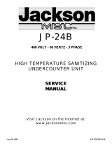
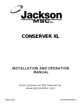
To aid in troubleshooting, the interface board contains six red LED (light emitting diodes). These diodes are illuminated whenever the
output signal to the corresponding control item is ON. The following example will illustrate the troubleshooting sequence that should be
used for all electrical control components. The wash pump runs at the first sequence of every cycle. The LED corresponding to the
wash pump motor contactor will be ON when the pump is to be On. If the LED is ON, and the pump motor is not running, measure the
voltage at the pump motor contactor coil (when the LED is on, meaning voltage should be applied to the coil from the interface board).
If there is no voltage, then replace the interface board. If there is voltage, then there is a problem in the pump motor and pump motor
contactor. If the display indicates that the machine is in a wash cycle, and both the pump motor is not running and the LED is not ON,
check the continuity of the cable that connects the controller board to the interface board. If continuity exists, replace the controller
board. If the controller board has been replaced and the problem still exists, replace the interface board.
The interface board contains six triacs, which are essentially electronic relays. Use a multimeter to verify that the interface board out-
put is supplying voltage to a control item (solenoid valve, peristaltic pump, motor contactor, etc.). During any troubleshooting, it is crit-
ical to remember that a 208-240 volt signal will always be measured at the outputs of the interface board (pins 1 through 8 on con-
nector J4) if the corresponding load (solenoid valve, peristaltic pump, motor contactor, etc.) is not connected to the output. To avoid
false readings, the control item that is being tested must be connected to the interface board output.
ELECTRONIC CONTROLLER BOARD REFERENCE
10
Drain Valve LED
Wash Pump LED
Rinse/Fill LED
Heater LED
Vent LED
Detergent Dispensing Pump LED

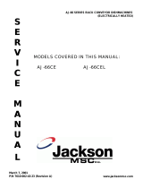
11
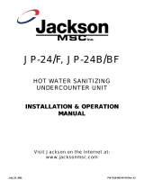
HORIZON HZ-24
ELECTRICAL DIAGRAM
208-240 volt, 50-60 hertz, 1 and 3 phase
/