AVENTICS Single valve, Series CL03 Owner's manual

Type
Owner's manual

This manual is also suitable for

R412018650/2018-11, Replaces: 2018-01, DE/EN/FR/IT/ES/SV
Einzelventil
Single valve
Distributeur isolé
Valvola singola
Válvula individual
Singelventil
CL03
Betriebsanleitung | Operating instructions | Notice d’instruction |
Istruzioni per l’uso | Instrucciones de servicio | Bruksanvisning
English
1 About this Documentation
These instructions contain important information on the safe and appropriate
assembly, operation, and maintenance of the product and how to remedy simple
malfunctions yourself.
O Read these instructions carefully, especially chapter 2 “Notes on safety”,
before you start working with the product.
Documentation validity
These instructions describe the following product:
CL03 single valve
Required and supplementary documentation
O Also follow the instructions for the other machine and system components.
O Observe the system documentation from the system manufacturer.
O Furthermore, observe general, statutory and other binding rules of the European
and national laws.
Presentation of information
Warnings
In this document, there are safety instructions before the steps whenever there
is a danger of personal injury or damage to the equipment. The measures described
to avoid these hazards must be followed.
Structure of warnings
Meaning of the signal words
Symbols
2 Notes on safety
The product has been manufactured according to the accepted rules of current
technology. Even so, there is a risk of injury or damage if the following general safety
instructions and the specific warnings given in this instruction manual are not
observed.
O Keep these instructions in a location where they are accessible to all users
at all times.
O Always include the operating instructions when you pass the product on
to third parties.
Intended use
The product is exclusively intended for installation in a machine or system or
for combination with other components to form a machine or system. The product
may only be commissioned after it has been installed in the machine or system
for which it is intended.
O Use of the CL03 single valve is permitted only under the operating conditions
and within the performance limits listed in the technical data.
O The CL03 single valve is only intended for industrial applications.
O Only use compressed air as the medium.
SIGNAL WORD
Hazard type and source
Consequences of non-observance
O Measures to avoid these hazards
WARNING
Indicates a hazardous situation which, if not avoided, could result in death
or serious injury.
CAUTION
Indicates a hazardous situation which, if not avoided, could result in minor
or moderate injuries.
NOTICE
Indicates that damage may be inflicted on the product or the environment.
Operation may be impaired if this information is disregarded.
Improper use
It is considered improper use if the CL03 single valve
O is used for any application not stated in these instructions or
O is used under operating conditions that deviate from those described
in these instructions.
Personnel qualifications
All tasks associated with the product require basic mechanical, pneumatic and
electrical knowledge, as well as knowledge of the respective technical terms.
In order to ensure operational safety, these tasks may only be carried out by
qualified personnel or an instructed person under the direction of qualified
personnel. Qualified personnel are those who can recognize possible hazards
and institute the appropriate safety measures, due to their professional training,
knowledge, and experience, as well as their understanding of the relevant
regulations pertaining to the work to be done. Qualified personnel must observe
the rules relevant to the subject area.
Notes on safety
General safety instructions
O Observe the regulations for accident prevention and environmental protection
in the country where the product is used and at the workplace.
O Only use the product within the performance range provided in the
technical data. You can find out more in the online catalog
(www.aventics.com/pneumatics-catalog).
O Do not place any mechanical loads on the product under any circumstances.
O This product may only be used for industrial applications (class A).
O Examine the product for obvious defects, such as cracks in the housing or
missing screws, caps, or seals.
During installation
O The warranty will not apply if the product is incorrectly assembled.
O Always make sure the relevant system component is not under pressure
or voltage before carrying out assembly work on the machine or system.
O Ensure the system cannot be switched on accidentally during assembly work.
O Observe the following standards when installing the system:
DIN EN 50178, classification VDE 0160
VDE 0100
During commissioning
O Installation may only be performed in a voltage-free and pressure-free state and
only by a qualified technician. Always carry out the installation in a pressure-free
state to avoid dangerous movements.
O Make sure that attached system components are properly secured.
O Do not put the CL03 valve system into operation before it is completely
assembled as well as correctly wired and configured, and after it has been
properly tested.
O Before commissioning versions that are subject to the restrictions of the
IP69K protection class, make sure that all the connection seals and plugs
are leaktight to prevent fluids and foreign particles from penetrating
the product.
During operation
O In certain applications there may be a risk of crush injuries. Always follow the site
safety instructions.
O Ensure an adequate exchange of air and sufficient cooling if the solenoid valves
are continuously loaded.
3 Delivery Contents
The delivery contents include:
W Operating instructions
W Base plate (without valve) and valve cover, IP69K
or
W Base plate with assembled valve and valve cover, IP69K
AVENTICS | CL03 | R412018650–BAL–001–AF | English 5
4About This Product
The CL03 single valve has been developed with a focus on hygienic design, chemical
resistance, protection class, modularity, and flexibility. It is intended for wash-down
applications in, for example, food processing and packaging.
Product description
The CL03 single valve is available in protection class IP69K.
An A-coded M12 round plug is used to provide the electric supply and control.
The available versions of the product may change over time. See the online catalog
(www.aventics.com/pneumatics-catalog) for a current description of available
versions.
Overview of CL03 single valve with base plate
and valve cover
Base plate overview
Valves
The valves direct the air to the pneumatic connections.
W 2x3/2 directional valves
W 5/2 directional valves
W 5/3 directional valves
Each valve has yellow LEDs indicating activation of:
W Solenoid 14 on valves with one solenoid
W Solenoid 14 or solenoid 12 on other valves.
The solenoid coils are controlled via the M12 plug. A yellow LED on the valve
indicates the current-carrying solenoids. The switch position assignment can be
recognized via the numbers 12 and 14.
You can find out more information about the valve options at “Technical Data” and in
the online catalog (www.aventics.com/pneumatics-catalog).
Manual override
Each valve has a manual override, “turn and detent” (yellow knob) or “turn”
(red knob) depending on the version. In both cases it is activated by a turning motion.
Do NOT press!
The switch position assignment can be recognized via the numbers 12 and 14.
5 Assembly
Check that the minimum or maximum values stated in the technical specifications
are not exceeded.
1 Base plate 5 Pneumatic connections
2 Valve 6 Mounting screws for valve
on base plate
3 Valve cover 7 Seal for valve cover
4 M12 round plug, A-coded, for control 8 Mounting screws for valve cover
1 Base plate 6 Connections 3 and 5
2 Port R for pilot exhaust air 7 VENT connection for pressure
equalization
3 Port X for external pilot control 8 M12 round plug, A-coded, for control
4 Connection 1 9 Pneumatic connections
5 Connections 2 and 4 10 Thread for mounting base plate to
mounting surface, M5
CAUTION
Danger of injury if assembled under pressure or voltage!
Assembling when under pressure or electrical voltage can lead to injuries and
damage to the product or system components.
O Make sure that the relevant system part is not under voltage or pressure
before you assemble the product.
O Protect the system against being restarted.
Uncontrolled movements of incorrectly connected compressed air lines.
Incorrectly assembled compressed air lines with plug connections could come
loose when pressure is applied to the single valve, resulting in injuries or damage
to the device.
O Always check that the plug connections are effective.
1
2
3
Assembling the CL03 single valve with base plate
and valve
The single valve may be mounted in any orientation.
Mounting base plates
O Mount the base plate of the single valve on a flat, firm surface using the threaded
mounting holes (10).
Positioning the valve and assembling the valve cover
1. Place the valve (2) on the base plate. Press gently on the valve’s electrical
connector end, making sure the contacts are straight and that the seal is seated
correctly. Make sure the contacts are straight and that the seal is seated
correctly.
2. Fasten the valve (2) by means of two self-tapping Pozidrive screws (6). Tightening
torque 1.1 ... 1.3 Nm screwdriver PZD no. 1.
3. Make sure that the manual override is in position 0. Carefully turn it into the zero
position, if required.
4. Mount the valve cover (3). Make sure the seal (7) is correctly positioned. Tighten
the three hexagon screws (8) with 1.0 ... 1.2 Nm.
Connecting the pneumatics on the CL03 single valve
The single valve is connected to the compressed air system via connections in the
base plate.
Pilot air is supplied externally via connection X, which is always present on the base
plate.
The pilot control valves are always exhausted via channel R.
O Fit exhaust air connections that are not connected to an exhaust air line with
a silencer.
O Provide unused connections with blanking plugs.
Pneumatic connections on the base plate
NOTICE
Risk of damage to the single valve
Incorrect screws, or too high torque, may damage the threaded mounting holes.
O Always use the screws supplied on delivery.
O Ensure correct assembly and the correct torque.
NOTICE
Risk of valve damage due to congested exhaust!
Closed exhaust outlets will lead to air congestion and valve damage.
The connection “VENT” in the base plate must also not be closed.
O Make sure that connection R is open and preferably provided with a silencer.
O Connect the “VENT” connection to a tube that exhausts the air outside the wet
zone. Alternatively, if the valve is mounted in a protected area, for example
in a cabinet, you can also fit a silencer to “VENT”.
O Ensure adequate ventilation through the exhaust air connection and
connection R.
Connection designation Connection type Dimension
1, 2, 3, 4, 5 Push-in fitting 8mm
Thread G1/8“
X
1)
, R
2)
, VENT
3)
1) External pilot control connection
2) Pilot control exhaust air connection
3) Ventilation connection
Push-in fitting 4mm
Thread M5
1
4
1
1
2
AVENTICS | CL03 | R412018650–BAL–001–AF | English 6
Connecting the single valve CL03 electrics
The CL03 single valve is supplied and controlled via the A-coded M12 round plug
(, 4).
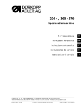
Assignment of the M12 plug, A-coded, on the single valve CL03
Proceed as follows:
1. Ensure that enough free space is left for the electrical connections so that the
permissible minimum bending radii are adhered to.
2. Insert the cable onto the round plug connector.
There are two controls (connector pins) permanently assigned to valve solenoids 12
and 14 for the valve position.
1. Only solenoid 14 must be connected for single solenoid valves. The second
control for solenoid 12 remains unused.
2. The following assignments are made in the 3/2 directional valves:
Solenoid 14 and pneumatic connection 4
Solenoid 12 and pneumatic connection 2
6 Commissioning and Operation
Step-by-step commissioning (step 1 ... 4)
Step 1: Checking the number of ports
1. Check the correct position of all fittings and connections.
2. Check the correct assembly of the electrical connection.
Step 2: Check assignment of the control signals
1. Make sure that the system is not under voltage or pressure.
2. Turn all manual overrides to the 0 position (see “Operating the manual override”).
3. Switch on the operating voltage.
4. Check the assignment of the control signals to the single valve.
The yellow LED is illuminated if the valve is being properly controlled.
O If the LED is not illuminated, check the assignment of the control signal
and the plug.
Step 3: Check the pneumatic functions
1. Make sure that the system is not under voltage or pressure.
2. Turn the manual override to position 0 (see “Operating the manual override”).
3. Make sure that all actuators are in their home positions and that there is no
danger from moving actuators.
CAUTION
Dangerous voltage
A power pack without safe isolation may lead to dangerous voltages in the event
of a malfunction. Injuries from electric shock and system damage may be the
consequences.
O Only use a power pack with safe isolation according to EN 60747, VDE 0551
classification! The corresponding electrical circuits are thus SELV/PELV
circuits in accordance with IEC 60364-4-41.
NOTICE
High current load
Current loads over 1 A per connector pin will damage the system.
O Do not exceed the permissible current load of 1 A per connector pin.
Pin Coil
1–
212
3COM
414
Commissioning may only be carried out by qualified electrical or pneumatic
personnel or an instructed person under the direction and supervision of
qualified personnel.
CAUTION
Undefined system state!
Danger of injury if the system is in an undefined state and if the manual overrides
are not set to zero.
O Before switching the system on, ensure that it is in a defined state!
1
4. Apply the compressed air to the system.
5. Examine the connected valve (and all other valves connected in the system if
necessary) using the manual override (see “Operating the manual override”).
6.
Replace the valve cover (see
“Positioning the valve and assembling the valve cover”).
Step 4: Switch on the system
1. Switch on the compressed air supply.
2. Switch on the operating voltage.
Operating the manual override
Turn and detent (yellow knob):
O Insert a screwdriver blade in the slot of the manual override and turn it from
position 0 to position 1 using slight force until it clicks into place.
The valve switches. The manual override remains in the switched position until it is
turned back to position 0. Depending on the valve construction, the valve then either
returns to the initial position or remains in the selected position.
Turn and release (red knob):
O Insert a screwdriver blade in the slot of the manual override and turn it from
position 0 to position 1 using slight force.
The manual override returns to position 0 when released.
Depending on the valve construction, the valve then either returns to the initial
position or remains in the selected position.
7 Service and Repairs
The CL03 single valve is maintenance-free and does not normally require any
particular service or maintenance.
Cleaning and care
O Note the information on maintenance and cleaning in the overall system
documentation.
O Only clean the single valve without valve cover using a dry cloth.
CAUTION
O Before applying compressed air to the system, check the stability of the
compressed air connections and make sure that no personnel are within the
hazardous zone when the compressed air supply is switched on.
CAUTION
Undefined system state!
Danger of injury if the system is in an undefined state and if the manual overrides
are not set to zero.
O Before switching the system on, ensure that it is in a defined state!
O Set all manual overrides to zero.
O Make sure that no personnel are within the hazardous zone when the
compressed air supply is switched on.
NOTICE
Manual override damage due to improper operation
The manual override will be damaged if it is operated improperly or with
excessive force.
O Exercise care and caution when actuating the manual override.
O Observe the following information for operation.
The manual override is a rotary switch. DO NOT press!
The valve control’s functional reliability and method of operation can be
checked before start-up by activating the valve functions using the manual
override (instead of the electrical signal). The electrical signal is disabled
when the manual override is used.
CAUTION
Applied electric voltage and high pressure!
Danger of injury from electric shocks and sudden pressure drops.
O Make sure the system is not pressurized or connected to power before
carrying out any service or maintenance work.
The IP69K version of the single valve has been designed for use in wet areas.
After correct assembly, it can therefore be cleaned under high pressure and
at high temperatures (IP69K conditions).
3
AVENTICS | CL03 | R412018650–BAL–001–AF | English 7
Maintenance
The single valve is maintenance-free.
O However, observe any stipulated maintenance intervals and requirements for the
entire system.
Checking the compressed air connections
O Regularly check the compressed air connections and compressed air lines for
leaks. Replace damaged or crushed lines.
8 Disassembly/Exchange
Disassembling the EV-CL03 from the mounting surface
1. Make sure the system is not under pressure or voltage before disassembly.
2. Loosen all connections.
3. Loosen all mounting screws on the CL03 single valve.
The valve can now be removed from the mounting surface.
9 Conversion and Extension
Exchange valve
1. Make sure the system is not under pressure or voltage before disassembly.
2. Remove the three hex head screws (8) on the valve cover (3) and then remove the
cover, including the seal (7).
3. Remove the cross recessed screws (6) on the valve (2) and then remove the
unscrewed valve from the base plate (1).
4. Place the new valve (5) on the base plate (1).
5. Press gently on the valve’s electrical connector end. Make sure the contacts are
straight and that the seal is seated correctly.
6. Fasten the valve (2) by means of two self-tapping Pozidrive screws (6). Tightening
torque 1.1 ... 1.3 Nm screwdriver PZD no. 1.
7. Make sure that the manual override is in position 0. Carefully turn it into the zero
position, if required.
8. Mount the valve cover (1). Make sure the seal (7) is correctly positioned. Tighten
the three hexagon screws (8) with 1.0 ... 1.2 Nm.
10 Disposal
O Comply with national regulations regarding disposal.
CAUTION
Voltage and high pressure
Danger of injury from electric shocks and sudden pressure drops.
O Make sure the system is not under pressure or voltage before performing the
following tasks:
Removing or connecting plugs
Disassembling the system
Exchanging individual components.
CAUTION
Voltage and high pressure
Danger of injury from electric shocks and sudden pressure drops.
O Make sure the system is not under pressure or voltage before performing the
following tasks:
Removing or connecting plugs
Disassembling the system
Exchanging individual components.
NOTICE
Risk of damage to the CL03 single valve
Too high pressure when connecting compressed air to the exhaust air connection
may damage the unit.
O Do not exceed 0.3 bar when connecting compressed air to the “VENT” port.
To ensure the IP69K protection after a modification, use the torques
specified in these instructions and also make sure that all seals are
correctly seated in their sealing slots. To check all seals, pressurize the
ventilation port “VENT” up to 0.3 bar and then check for leakages by using
soap water.
1
11 Troubleshooting
See the section “Disassembly/Exchange” for information on how to replace
a faulty product.
12 Technical Data
13 Spare Parts and Accessories
Information on spare parts and accessories can be found in the online catalog
(www.aventics.com/pneumatics-catalog).
General data
Mounting Via two M5 threaded mounting holes,
depth = 10 mm
Dimensions
See
Weight Depends on configuration,
see the online catalog
(www.aventics.com/pneumatics-catalog).
Operating temperature range 0 °C ... +50°C, without condensation
Storage temperature range –20 °C ... +70 °C
Protection acc. to EN 60529/IEC529 IP65, IP67, IP69K acc. to DIN EN 60529,
when assembled
Materials W Valve body,
base plate/
valve
W Seals
W Polyamide
W HNBR
Compressed air quality To DIN ISO 8573-1, class 6, 4, 3 or lower
Solid pollutants: ≤5μm
Dew point: ≤3°C
Oil content: ≤ 1 mg/m
3
Pneumatics
Control pressure 2.5 ... 10 bar
Operating pressure Vacuum to 10 bar, external pilot control
Nominal flow/valve 3/2 directional valve: 700 l/min
5/2 directional valve: 700 l/min
5/3 directional valve: 650 l/min
Electrics
Rated solenoid voltage u
n
24 VDC (–15 %/+20 %)
Power consumption
per solenoid P
20
0.35 W incl. LED and protective circuit
Indicator for switched valve LED yellow
Round plug M12, A-coded, 4-pin
4
AVENTICS | CL03 | R412018650–BAL–001–AF | English 8
Abbildungen: Ansicht variiert je nach Serie. / Figures: View varies according to the series. / Figures : la vue peut varier en fonction de la série.
Übersicht Einzelventil CL03 mit Grundplatte und Ventilabdeckung
Overview of CL03 single valve with base plate and valve cover
Vue d’ensemble du distributeur isolé CL03 avec embase et couvercle
1
2
Übersicht Grundplatte / Base plate overview / Vue d’ensemble de l’embase
Pos M
A
[Nm]
10 M5×10 2±0,2
2, 3, 7 M5 0,2+0,1
4, 5, 6 G1/8" 1,9+0,1
Einzelventil CL03 mit Grundplatte und Ventil montieren – Maßzeichnung
Assembling the CL03 single valve with base plate and valve – Dimensioned drawing
Montage du distributeur isolé CL03 avec embase et couvercle – Plan coté
4
00129025
max.
3 mm
Handhilfsbetätigung / Manual override / Commande manuelle auxiliaire
AVENTICS GmbH
Ulmer Straße 4
30880 Laatzen
Phone +49 (0) 5 11-21 36-0
Fax: +49 (0) 511-21 36-2 69
www.aventics.com
info@aventics.com
Further addresses:
www.aventics.com/contact
The data specified above only serve to
describe the product. No statements
concerning a certain condition or suitability
for a certain application can be derived
from our information. The given
information does not release the user from
the obligation of own judgement and
verification. It must be remembered that
our products are subject to a natural
process of wear and aging.
An example configuration is depicted on
the title page. The delivered p
roduct may
thus vary from that in the illustration.
Translation of the original operating
instructions. The original operating
instructions were created in the German
language.
R412018650–BAL–001–AF/2018-11
Subject to modifications. © All rights
reserved by AVENTICS GmbH, even and
especially in cases of proprietary rights
applications. It may not be reproduced or
given to third parties without its consent.
  • Page 1 1
  • Page 2 2
  • Page 3 3
  • Page 4 4
  • Page 5 5
  • Page 6 6
  • Page 7 7
  • Page 8 8
  • Page 9 9
  • Page 10 10
  • Page 11 11
  • Page 12 12
  • Page 13 13
  • Page 14 14
  • Page 15 15
  • Page 16 16
  • Page 17 17
  • Page 18 18
  • Page 19 19
  • Page 20 20
  • Page 21 21
  • Page 22 22
  • Page 23 23
  • Page 24 24
  • Page 25 25
  • Page 26 26
  • Page 27 27
  • Page 28 28
  • Page 29 29
  • Page 30 30
  • Page 31 31

AVENTICS Single valve, Series CL03 Owner's manual

Type
Owner's manual
This manual is also suitable for

Ask a question and I''ll find the answer in the document

Finding information in a document is now easier with AI