Robe Color Spot 700E AT v 2 0 User manual
- Category
- Stroboscopes & disco lights
- Type
- User manual

1
Wersion 2.0

2
Table of contents
1. Safety instructions ......................................................................................................... 3
2.Operating determinations ............................................................................................... 4
3. Description of the device ............................................................................................... 5
4. Installation....................................................................................................................... 6
4.1 Connection to the mains ............................................................................................
6
4.2 Fitting the lamp ........................................................................................................... 7
4.3 Lamp adjustment ....................................................................................................... 7
4.4 Replacing the colour lters,gobos and the animation wheel ..................................... 8
4.6 DMX-512 connection ................................................................................................
12
4.7 Ethernet connection ................................................................................................. 13
5.ColorSpot 700E AT - DMX Protocol ............................................................................. 15
6. Controller mode ........................................................................................................... 21
6.1 DMX addressing ....................................................................................................... 21
6.2 Remotely controllable functions ............................................................................... 21
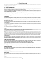
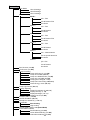
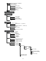
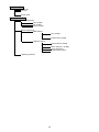
7.Control menu map ......................................................................................................... 23
8. Control menu ............................................................................................................... 27
8.1 Fixture Address ....................................................................................................... 27
8.2 Fixture information ................................................................................................... 27
8.3 Personality ............................................................................................................... 29
8.4 Lamp On/Off ............................................................................................................ 30
8.5 Test sequences ........................................................................................................ 30
8.6 Manual mode ........................................................................................................... 30
8.7 Stand-alone setting ................................................................................................. 31
8.8 Reset functions ........................................................................................................ 31
8.9 Special functions ...................................................................................................... 31
9. Power down mode ........................................................................................................ 33
10. RDM ............................................................................................................................. 33
11. Error and information messages .............................................................................. 34
12. Technical specications ............................................................................................ 36
13. Maintenance and cleaning ........................................................................................ 39
14.Appendix ...................................................................................................................... 41
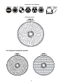
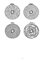
14.1 Standard effect conguration ................................................................................ 41
14.2 Optional animation wheels ..................................................................................... 42
ColorSpot 700E AT

3
CAUTION!
Keep this device away from rain and moisture!
Unplug mains lead before opening the housing!
FOR YOUR OWN SAFETY, PLEASE READ THIS USER MANUAL CAREFULLY
BEFORE YOU INITIAL START - UP!
1. Safety instructions
Every person involved with installation and maintenance of this device have to:
- be qualiled
- follow the instructions of this manual
CAUTION!
Be careful with your operations.
With a high voltage you can suffer
a dangerous electric shock when touching the wires!
This device has left our premises in absolutely perfect condition. In order to maintain this condition and to en-
sure a safe operation, it is absolutely necessary for the user to follow the safety instructions and warning notes
written in this manual.
Important:
The manufacturer will not accept liability for any resulting damages caused by the non-observance of this
manual or any unauthorized modication to the device.
Please consider that damages caused by manual modications to the device are not subject to warranty.
Never let the power-cord come into contact with other cables! Handle the power cord and all connections with
the mains with particular caution!
Make sure that the available voltage is not higher than stated on the rear panel.
Always plug in the power plug least. Make sure that the power-switch is set to off-position before you connect
the device to the mains. The power plug has to be accessable after installing the device.
Make sure that the power-cord is never crimped or damaged by sharp edges. Check the device and the power-
cord from time to time.
Always disconnect from the mains, when the device is not in use or before cleaning it. Only handle the power-
cord by the plug. Never pull out the plug by tugging the power cord.
This device falls under protection class I. Therefore it is essential to connect the yellow/green conductor to
earth.
The electric connection, repairs and servicing must be carried out by a qualied employee.
Do not connect this device to a dimmer pack.
Do not switch the xture on and off in short intervals as this would reduce the lamp’s life.
During the initial start-up some smoke or smell may arise. This is a normal process and does not necessarily
mean that the device is defective.
Do not touch the device’s housing bare hands during its operation (housing becomes hot)!
For replacement use lamps and fuses of same type and rating only.
CAUTION ! EYEDAMAGES !
Avoid looking directly into the light source
(meant especially for epileptics) !

4
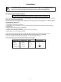
2.Operating determinations
This device is a moving-head for creating decorative effects and was designed for indoor use only.
If the device has been exposed to drastic temperature uctuation (e.g. after transportation), do not switch it on
immediately. The arising condensation water might damage your device. Leave the device switched off until
it has reached room temperature.
Never run the device without lamp!
Do not shake the device. Avoid brute force when installing or operating the device.
Never lift the xture by holding it at the projector-head, as the mechanics may be damaged. Always hold the
xture at the transport handles.
When choosing the installation-spot, please make sure that the device is not exposed to extreme heat, moisture
or dust. There should not be any cables lying around. You endanger your own and the safety of others!
The minimum distance between light output and the illuminated surface must be more than 3 meters.
Make sure that the area below the installation place is blocked when rigging, derigging or servicing the x-
ture.
Always x the xture with an appropriate safety rope. Fix the safety rope at the correct holes only.
Only operate the xture after having checked that the housing is rmly closed and all screws are tightly fas-
tened.
The lamp must never be ignited if the objective-lens or any housing-cover is open, as discharge lamps may
explose and emit a high ultraviolet radiation, which may cause burns.
The maximum ambient temperature 40°C must never be exceeded.
CAUTION!
The lens has to be replaced when it is obviously damaged,
so that its function is impaired, e. g. due to cracks or deep scratches!
Operate the device only after having familiarized with its functions. Do not permit operation by persons not
qualied for operating the device. Most damages are the result of unprofessional operation!
CAUTION!
The lamp has to be replaced when it is damaged
or deformed due to the heat!
Please use the original packaging if the device is to be transported.
Please consider that unauthorized modications on the device are forbidden due to safety reasons!
If this device will be operated in any way different to the one described in this manual, the product may suffer
damages and the guarantee becomes void. Furthermore, any other operation may lead to dangers like short-
circuit, burns, electric shock, burns due to ultraviolet radiation, lamp explosion, crash etc.

5
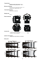
3. Description of the device
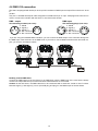
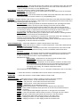
Rear panel of the base:
1 - Power switch
2 - Fuse holder-live
3 - Power cord
4 - Fuse holder-neutral
5 - 5-pin DMX output
6 - 5-pin DMX input
7 - 3-pin DMX output
8 - 3-pin DMX input
9 - RJ 45 connector
Front panel of the base:
1 - Ethernet indicator
2 - Display
3 - Infra-red sensor
4 - Data transfer indicator
5 - RNS control wheel
6 - Escape button
7 - Enter button
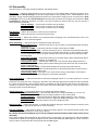
The head should be locked for transportation- the tilt lock button (7) is pushed and the pan lock/unlock lever
(2) is in locked position. To unlock the head, press the tilt unlock button (6) and move the pan lock/unlock latch
(2) into unlocked position.
1 - Front lens
2 - Pan lock
3 - Base
4 - Handle
5 - Head yoke
6 - Tilt unlock button (green)
7 - Tilt lock button (red)
8 - Moving head

6
4. Installation
Fixtures must be installed by a Qualied electrician in accordance with all
national and local electrical and construction codes and regulation.
4.1 Connection to the mains
For protection from electric shock,the xture must be earthed!
The ColorSpot 700E AT is equipped with auto-switching power supply that automatically adjusts to any 50/60Hz
AC power source from 100-240 Volts.
For use with 100-130 V supplies,the both main 6.3 A fuses has to be exchanged for 10 A fuses which
are enclosed in the packing.
To install the 10 A fuses:
1. Disconect the xture from AC power.
2. Unscrew the "live" fuseholder on the rear panel of the base with a at-tip screwdriver from the housing
(anticlockwise).
3. Remove the 6.3 A fuse from the fuseholder.
4. Put the 10 A fuse in the fuseholder.
5. Replace the fuseholder in the housing and screw it fully clockwise.
6.Repeat steps 2-5 for "neutral" fuseholder
If you need to t the power cable with a power plug that is suitable for your local AC power outlets,
installl a 3-prong grounding-type plug on the power cable. The earth has to be connected!
If you have any doubts about proper installation, consult a qualied electrician.
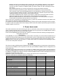
The occupation of the connection-cables is as follows:
Cable (EU) Cable (US) Pin International
Brown Black Live L
Light blue White Neutral N
Yellow/Green Green Earth

7
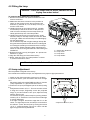
4.2 Fitting the lamp
DANGER ! Install the lamps with the device switched off only.
Unplug from mains before !
To insert the lamp (MSR GOLD 700 FastFit):
1. Disconnect the xture from power and allow it to cool
at least 15 minutes.
2. Make sure that xture´s head is in the position as
shown on the picture.Loosen the two quarter-turn
fasteners (1) marked “X,Y“ on the lamp cover (2) to
turn the cover down.
3. Holding the lamp by its ceramic base (3), carefully
turn the lamp to the left as shown on the picture in
order to loosen the lamp from the lamp holder (4).
Gently pull the lamp out of the lamp holder
4. Holding the new lamp by its ceramics base, gently
insert the lamp to the lamp socket and turn the base
to the right. Make sure that the lamp is installed tightly
into the lamp socket.
Do not install a lamp with a higher wattage! A lamp like
this generates temperatures the device is not designed
for. Damages caused by non-observance are not subje-
ct to warranty. Please follow the lamp manufacturer‘s
notes! Do not touch the glass bulb bare hand during the
installation!
5. Reinsert the lamp cover (2) and tighten two quarter-turn
fasteners (1) again.
6. Align the new lamp (see instructions below)
7. Reset „Lamp On Time” and „Lamp Strikes” counters
in „Fixture information” menu.
Do not operate this xture with open lamp cover!
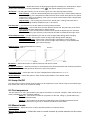
4.3 Lamp adjustment
The lamp holder is aligned at the factory.
Due to differences between lamps, ne adjustment may improve light performance:
1. Switch on the xture and after reset turn on the lamp.
2. Cancel all effects, open the shutter and focus the light
on a
at surface (wall) using either DMX controller or function
„Lamp adjustment” in „Special functions menu”.
3. Center the hot-spot (the brightest part of the beam) using
the
3 adjustment screws “A, B, C”. Turn one screw at a time
to drag the hot-spot, diagonally across the projected
image. If you cannot detect a hot -spot, adjust the lamp
until the light is even.
To reduce a hot-spot, pull the lamp in by turning all three
screws „A, B, C” clockwise 1/4-turn at a time until the light
is evenly distributed.
If the light is brighter around the edge than it is in the
center, or if light output is low, the lamp is too far back in
the reector. „Push” the lamp out by turning the screws
“A, B, C” counterclockwise 1/4-turn at a time until the
light is bright and evenly distributed.
1 - Quater-turn fasteners
2 - Lamp cover
3 - Lamp base
4 - Lamp holder
Remove the screws X and Y for re-lamping
3 adjustment scews “A, B, C”

8
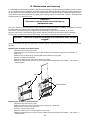
4.4 Replacing the colour lters,gobos and the animation wheel
DANGER!
Install the colour lters,gobos and animation wheel with the device switched off only.
Unplug from mains before!
Colour lters
1. Disconnect the xture from mains and allow it to cool.
2. Remove the bottom plastic cover of the head by loosening the 4 quarter-turn fasteners on the cover.
3. Turn the colour wheel to the desired position.The dichroic lters are xed on the colour wheel by the mag-
nets.
4.Break the magnet´s initial hold by skewing the dichroic lter in a direction outlined on the picture below.
Protect
the glass lter with a piece of paper or clout during this action.
5. Insert the new dichroic lter into colour wheel.
6. Replace the bottom cover before applying power.
Static gobos
1. Disconnect the xture from mains and allow it to cool.
2. Remove the top plastic cover of the head by loosening the 4 quarter-turn fasteners on the cover.
3. Gently bend out the gobo module to release it from the distance slots
and pull it up from the pressing
snap.
4. Insert the new gobo module back under the pressing snap and push it
to the 3 distance slots.
5. Replace the top cover before applying power.
Centering hole
Dichroic lter
Magnet

9
Rotating gobos
1. Disconnect the xture from mains and allow it to cool.
2. Remove the bottom plastic cover of the head by loosening the 4 quarter-turn fasteners on the cover.
3. Gently bend out the gobo module to release it from the distance slots
and pull it up from the pressing snap.
4. Remove the spring gobo-lock with an appro
priate tool (e.g. small-bladed screwdriver) and remove it.
Do not touch the surface of the pattern of the glass gobos as the oils from your hands can damage the
pattern.
5. Remove the original gobo and insert the new gobo (black and white glass gobos with glazy side
upwards-it means glazy side towards the lamp). Insert the spring gobo to secure it in the gobo holder.
6. Insert the the gobo module back under the pressing snap and push it
to the 3 distance slots.
5. Replace the bottom cover before applying power.
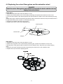
The animation wheel
The animation wheel is xed on its holder by the magnet and centered by the 3 guide-pins on the animation
wheel.
1. Disconnect the xture from mains and allow it to cool.
2. Remove the bottom plastic cover of the head by loosening the 4 quarter-turn fasteners on the cover.
3. To avoid bending the animation wheel while removing,break the magnet´s initial hold by prying the wheel
off with a small-bladed screwdriver gently inserted betwen the animation wheel and its holder.
4. Place the new animation wheel.Verify that the guide-pins are seated in its holder correctly correctly.
5. Replace the bottom cover before applying power.
Animation wheel
Animation wheel
with 3 guide-pins
Animation wheel holder
with 3 guide-holes

10
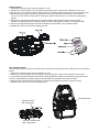
4.5 Rigging the xture
DANGER TO LIFE!
Please consider the respective national norms during the installation!
The installation of the projector has to be built and constructed in a way that it can hold 10 times the weight for
1 hour without any harming deformation.
The installation must always be secured with a secondary safety attachment, e.g. an appropriate catch net.
This secondary safety attachment must be constructed in a way that no part of the installation can fall down if
the main attachment fails.
When rigging, derigging or servicing the xture staying in the area below the installation place, on bridges,
under high working places and other endangered areas is forbidden.
The operator has to make sure that safety-relating and machine-technical installations are approved by an expert
before taking into operation for the rst time and after changes before taking into operation another time.
The operator has to make sure that safety-relating and machine-technical installations are approved by an
expert after every four year in the course of an acceptance test.
The operator has to make sure that safety-relating and machine-technical installations are approved by a skilled
person once a year.
The projector should be installed outside areas where persons may walk by or be seated.
IMPORTANT! OVERHEAD RIGGING REQUIRES EXTENSIVE EXPERIENCE, including (but not limited to)
calculating working load limits, installation material being used, and periodic safety inspection of all installation
material and the projector. If you lack these qualications, do not attempt the installation yourself, but instead use
a professional structural rigger. Improper installation can result in bodily injury and.or damage to property.
The projector has to be installed out of the reach of people.
If the projector shall be lowered from the ceiling or high joists, professional trussing systems have to be used.
The projector must never be xed swinging freely in the room.
Caution: Projectors may cause severe injuries when crashing down! If you have doubts concerning the safety
of a possible installation, do NOT install the projector!
Before rigging make sure that the installation area can hold a minimum point load of 10 times the projector’s
weight.
Danger of re !
When installing the device, make sure there is no highly inammable
material (decoration articles, etc.) in a distance of min. 1 m.
CAUTION!
Use 2 appropriate clamps to rig the xture on the truss.
Follow the instructions mentioned at the bottom of the base.
Make sure that the device is xed properly! Ensure that the
structure (truss)to which you are attaching the xtures is secure.
The projector can be placed directly on the stage oor or rigged in any orientation on a truss without altering
its operation characteristics .
For overhead use, always install a safety-rope that can hold at least 10 times the weight of the xture. You must
.

11
only use safety-ropes with screw-on carabines. Pull the safety-rope through the two apertures on the bottom of
the base and over the trussing system etc. Insert the end in the carabine and tighten the xation screw.
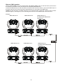
Fixation via the omega holders
1.Bolt each clamp (1) to the omega holder (4) with M12 bolt and lock nut through the hole in the holder.
2.Fasten the omega holders on the bottom of the base by inserting both quick-lock fasteners (3) into the holes
of the base and tighten fully clockwise.
3.Fasten the safety-rope (2) through the two apertures on the bottom of the base and over the trussing sys-
tem.
When installing xtures side-by-side,
avoid illuminating one xture with another!
DANGER TO LIFE!
Before taking into operation for the rst time,the installation has to be ap
-
proved by an expert!
1-Clamp
2-Safety-rope
3-Quick-lock fastener
4-Omega holder

12
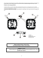
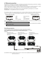
4.6 DMX-512 connection
The xture is equipped with both 3-pin and 5-pin XLR sockets for DMX input and output.The sockets are wired
in
parallel.
Only use a shielded twisted-pair cable designed for RS-485 and 3-pin or 5-pin XLR-plugs and connectors in
order to connect the controller with the xture or one xture with another.
DMX - output DMX-input
XLR mounting-sockets (rear view): XLR mounting-plugs (rear view):
If you are using the standard DMX controllers, you can connect the DMX output of the controller directly with
the DMX input of the rst xture in the DMX-chain. If you wish to connect DMX-controllers with other XLR-out-
puts, you need to use adapter-cables.
Building a serial DMX-chain:
Connect the DMX-output of the rst xture in the DMX-chain with the DMX-input of the next xture. Always
connect one output with the input of the next xture until all xtures are connected.
Caution: At the last xture, the DMX-cable has to be terminated with a terminator. Solder a 120 Ω resistor
between Signal (–) and Signal (+) into a 3-pin XLR-plug and plug it in the DMX-output of the last xture.
1 - Shield
2 - Signal (-)
3 - Signal (+)
4 - Not connected
5 - Not connected
1 - Shield
2 - Signal (-)
3 - Signal (+)
4 - Not connected
5 - Not connected

13
4.7 Ethernet connection
The xtures on a data link are connected to the Ethernet with Art-Net communication protocol.The controlling
software from PC (or lighting console) has to support Art-Net protocol.
Art-Net communication protocol is a 10 Base T Ethernet protocol based on the TCP/IP.Its purpose is to allow
transfer of large amounts of DMX 512 data over a wide area using standard network technology.
IP address is the Internet protocol address.The IP uniquely identies any node (xture) on a network.
The Universe is a single DMX 512 frame of 512 channels.
The ColorSpot 700E AT is equipped with 8-pin RJ- 45 socket for Ethernet input.Use a network cable category
5 (with four “twisted” wire pairs) and standard RJ-45 plugs in order to connect the xture to the network.
RJ-45 socket (front view): RJ-45 plug (front view):
1- TD+ 5- Not connected
2- TD- 6- RX-
3- RX+ 7- Not connected
4- Not connected 8- Not connected
Patch cables that connect xtures to the hubs or LAN sockets are wired 1:1,that is,pins with the same numbers
are connected together:
1-1 2-2 3-3 4-4 5-5 6-6 7-7 8-8
If only the xture and the computer are to be interconnected,no hubs or other active components are needed.A
cross-cable has to be used:
1-3 2-6 3-1 4-8 5-7 6-2 7-5 8-4
Direct Ethernet operation
Connect the Ethernet-inputs of all xtures in the xture chain with the network.
Option “ Ethernet” has to be selected from “Set Ethernet Mode” menu on the xture.
Set IP address (002.xxx.xxx.xxx / 010.xxx.xxx.xxx) and the Universe.
Example:
(DMX address=56) (DMX address=29) (DMX address=1)
IP addres=002.168.002.004 IP addres=002.168.002.003 IP addres=002.168.002.002
Universe=1 Universe=1 Universe=1
An advised PC setting: IP address: 002.xxx.xxx.xxx / 010.xxx.xxx.xxx (Different from xture IP addresses)
NET mask: 255.0.0.0

14
Ethernet / DMX operation
Options “Ethernet/DMX” has to be selected from “Set Ethernet Mode” menu on the rst xture (connected to
the network) in the xture chain,next xtures have standard DMX addresses.
Connect the Ethernet-input of the rst xture in the data chain with the network. Connect the DMX output of
this xture with the input of the next xture until all xtures are connected to the DMX chain.
Caution: At the last xture, the DMX chain has to be terminated with a terminator. Solder a 120 Ω resistor
between Signal (–) and Signal (+) into a XLR-plug and connect it in the DMX-output of the last xture.
Example:
DMX address=57 DMX address=29 (DMX address=1)
IP addres=002.168.002.002
Universe=0
DMX address=217 DMX address=29 (DMX address=1)
IP addres=002.168.002.003
Universe=1

15
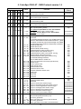
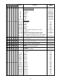
5. ColorSpot 700E AT - DMX Protocol-version 1.4
Mode/Channel
Value Function
Type of
control
1 2 3 4 5 6
1 1 1 1 26 1 0 - 255
Pan
Pan movement by 540°
proportional
2 2 2 2 27 - 0 - 255
Pan Fine
Fine control of pan movement
proportional
3 3 3 3 28 2 0 - 255
Tilt
Tilt movement by 280°
proportional
4 4 4 4 29 - 0 - 255
Tilt ne
Fine control of tilt movement
proportional
5 5 5 5 30 3
0
1 - 255
1 - 255
Pan/Tilt speed , Pan/Tilt time
Max. speed (tracking mode)
P./T. speed-set Speed Mode in menu: Pan/Tilt Mode
Speed from max. to min. (vector mode)
P./T. time - set Time Mode in menu: Pan/Tilt Mode
Time from 0.1 s to 25.5 s.
step
proportional
proportional
6 6 6 6 31 4
0 - 49
50 - 59
60 - 69
70 - 79
80 - 89
90 - 99
100 - 109
110 - 119
120-129
130 - 139
140 - 149
150 - 159
160 - 169
170 - 179
180 - 189
190 - 199
200 - 209
210 - 229
230 - 239
240 - 255
Power/Special functions
Reserved
To activate following functions, stop in DMX value for at
least 3 s and shutter must be closed at least 3 s. („Shut-
ter,Strobe” channel 34 (27) must be at range: 0-31 DMX).
Corresponding menu items are temporarily overriden).
Pan/Tilt speed mode
Pan/Tilt time mode
Blackout while pan/tilt moving
Disabled blackout while pan/tilt moving
Blackout while colour wheel moving
Disabled blackout while colour wheel moving
Blackout while gobo wheel moving
Disabled blackout while gobo wheel moving
To activate following functions,
stop in DMX value for at least 3 s.
Lamp On,reset(total reset except pan/tilt reset)
Pan/Tilt reset
Colour system reset
Gobo wheels reset
Dimmer/strobe reset
Zoom/focus/frost reset
Iris/prism/animation wheel reset
Total reset
Reserved
Lamp Off
Reserved
step
step
step
step
step
step
step
step
step
step
step
step
step
step
step
step
step
step
7 7 - - - -
0 - 9
10 - 31
32 - 63
64 - 95
96 - 127
128 - 159
160 - 191
192 - 223
224 - 255
Pan/Tilt macro selection
Disabled pan/tilt macro
Reserved
Figure of circle (from small to large)
Figure of horizontal eight (from small to large)
Figure of vertical eight (from small to large)
Figure of rectangle (from small to large)
Figure of triangle (from small to large)
Figure of star (from small to large)
Figure of cross (from small to large)
step
step
proportional
proportional
proportional
proportional
proportional
proportional
proportional
8 8 - - - -
0
1 - 127
128 - 129
130 - 255
Pan/Tilt macro speed
(Set pan/tilt speed (channel 5) at 0)
No macro generation
Macro generation from fast to slow-forwards
No macro generation
Macro generation from slow to fast-backwards
step
proportional
step
proportional

16
Mode/Channel
Value Function
Type of
control
1 2 3 4 5 6
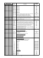
9 9 7 7 10 5
0
16
32
48
64
80
96
112
128-129
130-137
138-145
146-153
154-163
164-171
172-181
182-189
190 - 215
216 - 217
218 - 243
244 - 249
250 - 255
Colour wheel
Continual positioning
Open/white
Deep red
Deep blue
Orange
Green
Light red
Amber
UV lter
White
Positioning
Deep red
Deep blue
Orange
Green
Light red
Amber
UV lter
Forwards rainbow effect from fast to slow
No rotation
Backwards rainbow effect from slow to fast
Random colour selection by audio control
(Set microphone sensitivity in menu „Personality”)
Auto random colour selection from fast to slow
proportiona
proportiona
proportiona
proportional
proportional
proportional
proportional
proportional
proportional
step
step
step
step
step
step
step
proportional
step
proportional
step
proportional
10 - 8 - 11 -
0 - 255
Colour wheel - ne positioning
Fine positioning proportional
11 10 9 8 4 6
0 - 255
Cyan
Cyan (0-white, 255-full cyan) proportional
12 11 10 9 6 7
0 - 255
Magenta
Magenta (0-white, 255-full magenta) proportional
13 12 11 10 8 8
0 - 255
Yellow
Yellow (0-white, 255-full yellow) proportional
14 13 12 11 - 9
0 - 255
CTO lter
(0-6000K, 255-3200K) proportional
15 14 13 12 16 10
0 - 7
8 - 15
16 -23
24-31
32-39
40-47
48-55
56-63
64-71
72-79
80-87
88-95
96-103
104-111
112-119
120-127
128-135
136-143
144-151
152-159
CMY colour macros
No function
Macro 1
Macro 2
Macro 3
Macro 4
Macro 5
Macro 6
Macro 7
Macro 8
Macro 9
Macro 10
Macro 11
Macro 12
Macro 13
Macro 14
Macro 15
Macro 16
Macro 17
Macro 18
Macro 19
step
step
step
step
step
step
step
step
step
step
step
step
step
step
step
step
step
step
step
step

17
Mode/Channel
Value Function
Type of
control
1 2 3 4 5 6
15 14 13 12 16 10
160-167
168-175
176-183
184-191
192-199
200 - 207
208 - 215
216 - 223
224 - 231
232 - 239
240 - 243
244 - 249
250 - 255
Macro 20
Macro 21
Macro 22
Macro 23
Macro 24
Macro 25
Macro 26
Macro 27
Macro 28
Macro 29
Macro 30 - Random rainbow effect from fast to slow
Random macro selection by audio control
(Set microphone sensitivity in menu "PErS")
Auto random macro selection from fast to slow
step
step
step
step
step
step
step
step
step
step
proportional
step
proportional
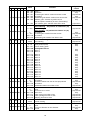
16 15 14 13 - 11
0 - 255
Effect Speed
Speed of CMY&CTO and Rot. gobo selection
Speed from max. to min. proportional
17 16 15 14 17 12
0-31
32-47
48-63
64-79
80-95
96-111
112-127
128-191
192-255
Animation wheel
Open
Horizontal indexed position-set indexing on channel18 (17)
Vertical indexed position-set indexing on channel 18 (17)
Cont.rotation,horizon. position-set speed on channel 18 (17)
Cont.rotation,vertical. position-set speed on channel 18 (17)
Horizontal pulse effects-set speed on channel 18 (17)
Vertical pulse effects-set speed on channel 18 (17)
Indexed angle position from horizont. to vert. with indexing
(set indexing on channel 18 (17))
Indexed angle position from vertic. to horizont. with rotation
(set rotation on channel 18 (17))
step
step
step
step
step
step
step
step
step
18 17 16 15 18 13
0
1-127
128-129
130-255
0-255
0-255
Animation wheel rotation and indexing
Rotation of animation wheel
No rotation
Forward rotation from fast to slow
No rotation
Backward rotation from slow to fast
Indexing of animation wheel
Indexed angle
Speed of pulse offects
From fast to slow
step
proportional
step
proportional
proportional
proportional
19 18 17 16 15 14
0
7
13
19
26
32
39
45
51
58
64
65 - 69
70 - 74
75 - 79
80 - 84
85 - 89
Static gobo wheel
Continual Positioning
In range 0-64 DMX is possible ne gobo
positioning - set value on channel 20
Open/hole
Gobo 1
Gobo 2
Gobo 3
Gobo 4
Gobo 5
Gobo 6
Gobo 7
Gobo 8
Gobo 9
Open/hole
Positioning
Gobo 1
Gobo 2
Gobo 3
Gobo 4
Gobo 5
proportional
proportional
proportional
proportional
proportional
proportional
proportional
proportional
proportional
proportional
proportional
step
step
step
step
step

18
Mode/Channel
Value Function
Type of
control
1 2 3 4 5 6
19 18 17 16 15 14
90 - 94
95 - 99
100 - 104
105 - 109
110 - 119
120 - 129
130 - 139
140 - 149
150 - 159
160 - 169
170 - 179
180 - 189
190 - 199
200 - 201
202 - 221
222 - 223
224 - 243
244 - 249
250 - 255
Gobo 6
Gobo 7
Gobo 8
Gobo 9
Shaking gobos from slow to fast
Gobo 1
Gobo 2
Gobo 3
Gobo 4
Gobo 5
Gobo 6
Gobo 7
Gobo 8
Gobo 9
Open/hole
Forwards gobo wheel rotation from fast to slow
No rotation
Backwards gobo wheel rotation from slow to fast
Random gobo selection by audio control
(Set microphone sensitivity in menu „Personality”)
Auto random gobo selection from fast to slow
step
step
step
step
proportional
proportional
proportional
proportional
proportional
proportional
proportional
proportional
proportional
proportional
proportional
step
proportiona
20 - 18 - - -
0-255
Fine static gobo wheel
Fine positioning
proportional
21 19 19 17 12 15
0-3
4-7
8-11
12-15
16-19
20-23
24-27
28-31
32-35
36-39
40-43
44-47
48-51
52-55
56-59
60-69
70-79
80-89
90-99
100-109
110-119
120-129
130 - 139
140 - 149
150 - 159
160 - 169
170 - 179
180 - 189
Rotating gobo wheel
Index - set indexing on channel 22 (20)
Open/hole
Gobo 1
Gobo 2
Gobo 3
Gobo 4
Gobo 5
Gobo 6
Gobo 7
Rotation - set rotation on channel 22 (20)
Gobo 1
Gobo 2
Gobo 3
Gobo 4
Gobo 5
Gobo 6
Gobo 7
Shaking gobos from slow to fast
Index - set indexing on channel 22 (20)
Gobo 1
Gobo 2
Gobo 3
Gobo 4
Gobo 5
Gobo 6
Gobo 7
Positioning - Shaking gobos from slow to fast
Rotation - set rotation on channel 22 (20)
Gobo 1
Gobo 2
Gobo 3
Gobo 4
Gobo 5
Gobo 6
step
step
step
step
step
step
step
stepl
step
step
step
step
step
step
step
proportional
proportional
proportional
proportional
proportional
proportional
proportional
proportional
proportional
proportional
proportional
proportional
proportional

19
Mode/channel
Value Function
Type of
control
1 2 3 4 5 6
21 19 19 17 12 15
190 - 199
200 - 201
202 - 221
222 - 223
224 - 243
244 - 249
250 - 255
Gobo 7
Open/hole
Forwards gobo wheel rotation from fast to slow
No rotation
Backwards gobo wheel rotation from slow to fast
Random gobo selection by audio control
(Set microphone sensitivity in menu „Personality”)
Auto random gobo selection from fast to slow
proportional
step
proportional
step
proportional
step
proportiona
22 20 20 18 13 16
0 - 255
0
1 - 127
128 - 129
130 - 255
Rot. gobo indexing and rotation
Gobo indexing - set position on channel 21 (19)
Gobo indexing
Gobo rotation - set position on channel 21 (19)
No rotation
Forwards gobo rotation from fast to slow
No rotation
Backwards gobo rotation from slow to fast
proportional
step
proportional
step
proportional
23 - 21 - 14 -
0-255
Gobo ne indexing
Fine indexing proportional
0 - 19
20 - 127
128 - 255
128 - 135
136 - 143
Prism
Open position (hole)
3-facet rotating prism
Prism/gobo macros
Macro 1
Macro 2
step
step
step
step
24 21 22 19 19 17
144 - 151
152 - 159
160 - 167
168 - 175
176 - 183
184 - 191
192 - 199
200 - 207
208 - 215
216 - 223
224 - 231
232 - 239
240 - 247
248 - 255
Macro 3
Macro 4
Macro 5
Macro 6
Macro 7
Macro 8
Macro 9
Macro 10
Macro 11
Macro 12
Macro 13
Macro 14
Macro 15
Macro 16
step
step
step
step
step
step
step
step
step
step
step
step
step
step
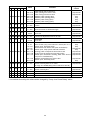
25 22 23 20 - 18
0
1 - 127
128 - 129
130 - 255
Prism rotation
No rotation
Forwards rotation from fast to slow proportional
No rotation
Backwards rotation from slow to fast
step
proportional
step
proportional
26 23 24 21 - 19
0
1 - 179
180 - 189
190 - 211
212 - 233
234 - 255
Frost
Open
Frost from 0% to 100%
100% frost
Pulse closing from slow to fast
Pulse opening from fast to slow
Ramping from fast to slow
step
proportional
step
proportional
proportional
proportional
27 - 25 - - -
0-255
Frost ne
Smooth frosting proportional
28 24 26 22 20 20
0
1 - 179
180 - 191
Iris
Open
From max.diameter to min.diameter
Closed
step
proportional
step

20
Mode/Channel
Value Function
Type of
control
1 2 3 4 5 6
28 24 26 22 20 20
192 -219
220 - 247
248 - 249
250 - 251
252 - 253
254 - 255
Pulse effects with Iris blackout:
Pulse opening from slow to fast
Pulse closing from fast to slow
Random pulse opening (fast)
Random pulse opening (slow)
Random pulse closing (fast)
Random pulse closing (slow)
proportional
proportional
step
step
step
step
29 - 27 - 21 -
0 - 255
Iris ne
Iris ne proportional
30 25 28 23 24 21
0 - 255
Zoom
Zoom from max. to min.beam angle proportional
31 - 29 - 25 -
0-255
Zoom ne
Zoom ne proportional
32 26 30 24 22 22
0 - 255
Focus
Continuous adjustment from far to near proportional
33 - 31 - 23 -
0- 255
Focus ne
Focus ne proportional
34 27 32 25 1 23
0 - 31
32 - 63
64 - 95
96 - 127
128 - 143
144 - 159
160 - 191
192 - 223
224 - 255
Shutter, strobe
Shutter closed, Lamp power reduced to 350 W (after 10 s*)
Shutter open, Full lamp power
Strobe-effect from slow to fast (max.12 ashes/s)
Shutter open, Lamp power reduced to 350 W
Opening pulse in sequences from slow to fast
Closing pulse in sequences from fast to slow
Shutter open, Electronic strobing „ZAP” from slow to
fast (from 7 to 33 ashes/s)
Random strobe-effect from slow to fast
Shutter open, Full lamp power
step
step
proportional
step
proportional
proportional
proportional
proportional
step
35 28 33 26 2 24
0 - 255
Dimmer intensity
Dimmer intensity from 0% to 100%
(In range of 0-8 DMX,lamp power reduced to 350 W)
proportional
36 - 34 - 3 -
0 - 255
Fine dimmer intensity
Dimmer intensity ne proportional
- - - - 5 - No function
- - - - 7 - No function
- - - - 9 - No function
* 10s=default time delay,this value can be changed by "Lamp Low Power Delay" menu.
Page is loading ...
Page is loading ...
Page is loading ...
Page is loading ...
Page is loading ...
Page is loading ...
Page is loading ...
Page is loading ...
Page is loading ...
Page is loading ...
Page is loading ...
Page is loading ...
Page is loading ...
Page is loading ...
Page is loading ...
Page is loading ...
Page is loading ...
Page is loading ...
Page is loading ...
Page is loading ...
Page is loading ...
Page is loading ...
Page is loading ...
Page is loading ...
-
 1
1
-
 2
2
-
 3
3
-
 4
4
-
 5
5
-
 6
6
-
 7
7
-
 8
8
-
 9
9
-
 10
10
-
 11
11
-
 12
12
-
 13
13
-
 14
14
-
 15
15
-
 16
16
-
 17
17
-
 18
18
-
 19
19
-
 20
20
-
 21
21
-
 22
22
-
 23
23
-
 24
24
-
 25
25
-
 26
26
-
 27
27
-
 28
28
-
 29
29
-
 30
30
-
 31
31
-
 32
32
-
 33
33
-
 34
34
-
 35
35
-
 36
36
-
 37
37
-
 38
38
-
 39
39
-
 40
40
-
 41
41
-
 42
42
-
 43
43
-
 44
44


Robe Color Spot 700E AT v 2 0 User manual
- Category
- Stroboscopes & disco lights
- Type
- User manual
Ask a question and I''ll find the answer in the document
Finding information in a document is now easier with AI
Related papers
-
Robe Color Spot250AT User manual
-
-
-
-
-
-
-
-
-
Other documents
-
 Microh Profile Spot PZM User manual
-
 CK Light CK407 Hand Manual
-
Robin 300 plasma spot User manual
-
 Microh ULTRA SPOT 575 User manual
-
 Astrolite X-TORM 300 User manual
-
-
-
 leahua LH-N006 User manual
-
 FOS Technologies FOS 12R Hybrid User manual
-


