44
44
4
Important safety Instructions
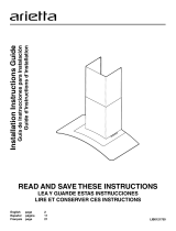
READ AND SAVE THESE INSTRUCTIONS
Automatically Operated Device - TAutomatically Operated Device - T
Automatically Operated Device - TAutomatically Operated Device - T
Automatically Operated Device - T
o Reduce Theo Reduce The
o Reduce Theo Reduce The
o Reduce The
Risk Of Injury Disconnect FrRisk Of Injury Disconnect Fr
Risk Of Injury Disconnect FrRisk Of Injury Disconnect Fr
Risk Of Injury Disconnect Fr
om Power Supplyom Power Supply
om Power Supplyom Power Supply
om Power Supply
BeforBefor
BeforBefor
Befor
e Servicing.e Servicing.
e Servicing.e Servicing.
e Servicing.
TO REDUCE THE RISK OF A RANGE TOP GREASE
FIRE.
a) Never leave surface units unattended at high settings.
Boilovers cause smoking and greasy spillovers that may
ignite. Heat oils slowly on low or medium settings.
b) Always turn hood ON when cooking at high heat or
when ambeing food (I.e. Crepes Suzette, Cherries
Jubilee, Peppercorn Beef Flambe’).
c) Clean ventilating fans frequently. Grease should not
be allowed to accumulate on fan or lter.
d) Use proper pan size. Always use cookware appropri-
ate for the size of the surface element.
TO REDUCE THE RISK OF INJURY TO PERSONS, IN
THE EVENT OF A RANGE TOP GREASE FIRE, OB-
SERVE THE FOLLOWING:
a) SMOTHER FLAMES with a close-tting lid, cookie
sheet, or other metal tray, then turn o the gas burner
or the electric element. BE CAREFUL TO PREVENT
BURNS. If the ames do not go out immediately,
EVACUATE AND CALL THE FIRE DEPARTMENT.
b) NEVER PICK UP A FLAMING PAN - you may be
burned.
c) DO NOT USE WATER, including wet dishcloths or tow-
els - a violent steam explosion will result.
d) Use an extinguisher ONLY if:
1) You know you have a class ABC extinguisher, and
you already know how to operate it.
2) The re is small and contained in the area where it
started.
3) The re department is being called.
4) You can ght the re with your back to an exit.
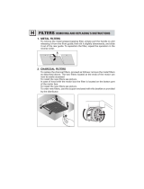
OPERATION
a. Always leave safety grills and lters in place. Without
these components, operating blowers could catch onto hair,
ngers and loose clothing.
The manufacturer declines all responsibility in the event
of failure to observe the instructions given here for instal-
lation, maintenance and suitable use of the product. The
manufacturer further declines all responsibility for injury
due to negligence and the warranty of the unit automati-
cally expires due to improper maintenance.
Important safety Instructions
FOR GENERAL VENTILATING USE ONLY. DO NOT USE
TO EXHAUST HAZARDOUS OR EXPLOSIVE MATERI-
ALS OR VAPORS.
TO REDUCE THE RISK OF FIRE, ELECTRIC SHOCK,
OR INJURY TO PERSONS, OBSERVE THE FOL-
LOWING:
A. Use this unit only in the manner intended by the manu-
facturer. If you have questions, contact the manufac-
turer.
B. Before servicing or cleaning the unit, switch power o
at service panel and lock service panel disconnecting
means to prevent power from being switched on acci-
dentally. When the service disconnecting means can-
not be locked, securely fasten a prominent warning
device, such as a tag, to the service panel.
C. Installation Work and Electrical Wiring Must Be Done
By Qualied Person(s) In Accordance With All Appli-
cable Codes & Standards, Including Fire-rated Con-
struction.
D. Sucient air is needed for proper combustion and ex-
hausting of gases through the ue (Chimney) of fuel
burning equipment to prevent back- drafting. Follow
the heating equipment manufacturers guideline and
safety standards such as those published by the Na-
tional Fire Protection Association (NFPA), the Ameri-
can Society for Heating, Refrigeration and Air Condi-
tioning Engineers (ASHRAE), and the local code au-
thorities.
E. When cutting or drilling into wall or ceiling, do not dam-
age electrical wiring
and other hidden utilities.
F. Ducted systems must always be vented to the outdoors.
To reduce risk of re and to properly exhaust air, be
sure to duct air outside - do not vent exhaust air into
spaces within walls, ceilings, attics, crawl spaces, or
garages.
TO REDUCE THE RISK OF FIRE, USE ONLY METAL
DUCT WORK.
Install this hood in accordance with all requirements speci-
ed.
To Reduce The Risk Of Fire Or Electric Shock, Do Not
Use This Hood With Any External Solid State Speed
Control Device.