Page is loading ...

USER GUIDE & SERVICE MANUAL
SAFETY • INSTALLATION & INTEGRATION • OPERATING INSTRUCTIONS • MAINTENANCE • SERVICE
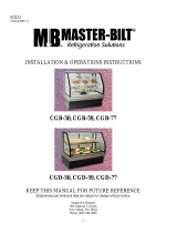
ADA Series •
ADA24R •
24" Solid Door Refrigerator
RIGHT PRODUCT. RIGHT PLACE. RIGHT TEMPERATURE. SINCE 1962.

USER GUIDE & SERVICE MANUAL
u-line.com
Table of Contents
Intro
Safety
Safety and Warning
Disposal And Recycling
Installation
Environmental Requirements
Electrical
Cutout Dimensions
Product Dimensions
Side by Side Installation
Anti-Tip Bracket
General Installation
Grille / Plinth Installation
Door Swing
Door Adjust
Maintenance
Cleaning
Cleaning Condenser
Extended Non-Use
Operating Instructions
First Use
Control Operation
Sabbath Mode
Airflow and Product Loading
Service
Interior Shelves
Troubleshooting
Wire Diagram
Product Liability
Warranty Claims
Parts
Ordering Replacement Parts
R600a Specifications
System Diagnosis Guide
Compressor Specifications
Troubleshooting Extended
Control Operation - Service
Thermistor
Defrost
Remove Fan and Cover
Warranty

USER GUIDE
Introduction 1
u-line.com
WELCOME TO U-LINE
Congratulations on your U-Line purchase. Your product comes from a company with over five decades of premium modular
ice making, refrigeration, and wine preservation experience. U-Line continues to be the American leader, delivering versatility
and flexibility for multiple applications including residential, light commercial, outdoor and marine use. U-Line’s complete
product collection includes Wine Captain
®
Models, Beverage Centers, Clear Ice Machines, Crescent Ice Makers, Glass & Solid
Door Refrigerators, Drawer Models, Freezers, Combo
®
Models, and more.
U-Line has captivated those with an appreciation for the finer things with exceptional functionality, style, inspired innovations
and attention to even the smallest details. We are known and respected for our unwavering dedication to product design,
quality and selection. U-Line is headquartered in Milwaukee, Wisconsin and has shipped product to five continents for over
two decades and is proud to have the opportunity to ship to you.
PRODUCT INFORMATION
Looking for additional information on your product? User Guides, Spec Sheets, CAD Drawings, Compliance Documentation,
and Product Warranty information are all available for reference and download at u-line.com.
PROPERTY DAMAGE / INJURY CONCERNS
In the unlikely event property damage or personal injury is suspected related to a U-Line product, please take the following
steps:
1. U-Line Customer Care must be contacted immediately at +1.800.779.2547.
2. Service or repairs performed on the unit without prior written approval from U-Line is not permitted. If the unit has been
altered or repaired in the field without prior written approval from U-Line, claims will not be eligible.
GENERAL INQUIRIES
U-Line Corporation
8900 N. 55th Street
Milwaukee, Wisconsin 53223 USA
Monday - Friday 8:00 am to 4:30 pm CST
T: +1.414.354.0300
F: +1.414.354.7905
Email: sales@u-line.com
u-line.com
SERVICE & PARTS ASSISTANCE
Monday - Friday 8:00 am to 4:30 pm CST
T: +1.800.779.2547
F: +1.414.354.5696
Service Email: onlineservice@u-line.com
Parts Email: onlineparts@u-line.com
CONNECT WITH US
Designed, engineered and assembled in WI, USA
3

USER GUIDE
Safety and Warning 1
u-line.com
SAFETY • INSTALLATION & INTEGRATION • OPERATING INSTRUCTIONS • MAINTENANCE • SERVICE
Safety and Warning
NOTICE
Please read all instructions before installing,
operating, or servicing the appliance.
Use this appliance for its intended purpose only and follow
these general precautions with those listed throughout this
guide:
SAFETY ALERT DEFINITIONS
Throughout this guide are safety items labeled with a
Danger, Warning or Caution based on the risk type:
DANGER
!
Danger means that failure to follow this safety
statement will result in severe personal injury or
death.
WARNING
!
Warning means that failure to follow this safety
statement could result in serious personal injury
or death.
CAUTION
!
Caution means that failure to follow this safety
statement may result in minor or moderate
personal injury, property or equipment damage.
DANGER
!
This unit contains R600a (Isobutane) which is a
flammable hydrocarbon. It is safe for regular
use. Do not use sharp objects to expedite
defrosting. Do not service without consulting the
“R600a specifications” section included in the
User Guide. Do not damage the refrigerant
circuit.
WARNING
!
Service must be done by factory authorized
service personnel. Any parts shall be replaced
with like components. Failure to comply could
increase the risk of possible ignition due to
incorrect parts or improper service.
4

USER GUIDE
Disposal and Recycling 1
u-line.com
SAFETY • INSTALLATION & INTEGRATION • OPERATING INSTRUCTIONS • MAINTENANCE • SERVICE
Disposal and Recycling
DANGER
!
RISK OF CHILD ENTRAPMENT. Before you throw
away your old refrigerator or freezer, take off
the doors and leave shelves in place so children
may not easily climb inside.
If the unit is being removed from service for disposal,
check and obey all federal, state and local regulations
regarding the disposal and recycling of refrigeration
appliances, and follow these steps completely:
1. Remove all consumable contents from the unit.
2. Unplug the electrical cord from its socket.
3. Remove the door(s)/drawer(s).
5

USER GUIDE
Environmental Requirements 1
u-line.com
SAFETY • INSTALLATION & INTEGRATION • OPERATING INSTRUCTIONS • MAINTENANCE • SERVICE
Environmental Requirements
This model is intended for indoor/interior applications only
and is not to be used in installations that are open/
exposed to natural elements.
This unit is designed to operate between 50°F (10°C) and
100°F (38°C). Higher ambient temperatures may reduce
the unit’s ability to reach low temperatures and/or reduce
ice production on applicable models.
For best performance, keep the unit out of direct sunlight
and away from heat generating equipment.
In climates where high humidity and dew points are
present, condensation may appear on outside surfaces.
This is considered normal. The condensation will
evaporate when the humidity drops.
CAUTION
!
Damages caused by ambient temperatures of
40°F (4°C) or below are not covered by the
warranty.
6

USER GUIDE
Electrical
u-line.com
Electrical
WARNING
!
SHOCK HAZARD — Electrical Grounding
Required. Never attempt to repair or perform
maintenance on the unit until the electricity has
been disconnected.
Never remove the round grounding prong from
the plug and never use a two-prong grounding
adapter.
Altering, cutting or removing power cord,
removing power plug, or direct wiring can cause
serious injury, fire, loss of property and/or life,
and will void the warranty.
Never use an extension cord to connect power to
the unit.
Always keep your working area dry.
NOTICE
Electrical installation must observe all state and
local codes. This unit requires connection to a
grounded (three-prong), polarized receptacle
that has been placed by a qualified electrician.
The unit requires a grounded and polarized 115 VAC,
60 Hz, 15A power supply (normal household current). An
individual, properly grounded branch circuit or circuit
breaker is recommended. A GFCI (ground fault circuit
interrupter) is usually not required for fixed location
appliances and is not recommended for your unit because
it could be prone to nuisance tripping. However, be sure
to consult your local codes.
See CUTOUT DIMENSIONS for recommended receptacle
location.
7

USER GUIDE
Cutout Dimensions 1
u-line.com
SAFETY • INSTALLATION & INTEGRATION • OPERATING INSTRUCTIONS • MAINTENANCE • SERVICE
Cutout Dimensions
PREPARE SITE
Your U-Line product has been designed for either free-
standing or built-in installation. When built-in, your unit
does not require additional air space for top, sides, or
rear. However, the front grille must NOT be obstructed,
and clearance is required for an electrical connection in
the rear.
CAUTION
!
Unit can NOT be installed behind a closed cabinet
door.
CUTOUT DIMENSIONS
4"
(102 mm)
7"
(178 mm)
24"
(610 mm)
24-1/4"
(616 mm)
32"
(813 mm)
to
33"
(838 mm)
Preferred location
for electrical
outlet is in
adjacent
cabinet.
5/8"
(16 mm)
8

USER GUIDE
Product Dimensions 1
u-line.com
SAFETY • INSTALLATION & INTEGRATION • OPERATING INSTRUCTIONS • MAINTENANCE • SERVICE
Product Dimensions
23-1/4" (591 mm)
32" to 33”
(813 mm 838 mm)
24" (610 mm)
Not Including Handle
9

USER GUIDE
Side-by-Side Installation
u-line.com
Side-by-Side Installation
Two units may be installed side-by-side.
Cutout width for a side-by-side installation is the cutout
dimension of a single unit times two.
No trim kit is required. However, 1/4" (6 mm) of space
needs to be maintained between the units to ensure
unobstructed door swing.
Units must operate from separate, properly grounded
electrical receptacles placed according to each unit’s
electrical specifications requirements.
Side-by-Side Installation with Bracket
1. Slide both units out so screws on top of units are easily
accessible.
2. Remove screws as shown below.
3. Place bracket over holes and attach to unit with two
screws removed in step 2 using a T-25 Torx driver.
Tighten screws fully.
4. Gently push units into position. Be careful not to
entangle the electrical cord or water line, if applicable.
5. Re-check the leveling, from front to back and side to
side. Make any necessary adjustments. The unit’s top
surface should be approximately 1/8" (3 mm) below
the countertop.
10

USER GUIDE
Anti-Tip Bracket 1
u-line.com
SAFETY • INSTALLATION & INTEGRATION • OPERATING INSTRUCTIONS • MAINTENANCE • SERVICE
Anti-Tip Bracket
1. Slide unit out so screws on top of unit are easily
accessible.
2. Remove the two screws from the opposite side of the
hinge assembly using a T-25 Torx driver (see below).
NOTE: 1224 models shown with four screw. 1215 models
only have three screws, but same screws are used in both
applications.
3. Place bracket (part #14154) over holes and attach to
unit with two screws removed in step 2 using a T-25
Torx driver. Tighten screws fully.
4. Gently push unit into position. Be careful not to
entangle the electrical cord or water line, if applicable.
5. Check to be sure the unit is level from front to back
and side to side. Make any necessary adjustments.
The unit’s top surface should be approximately 1/8"
(3 mm) below the countertop.
6. Secure bracket into adjoining surface.
11

USER GUIDE
General Installation 1
u-line.com
SAFETY • INSTALLATION & INTEGRATION • OPERATING INSTRUCTIONS • MAINTENANCE • SERVICE
General Installation
LEVELING INFORMATION
1. Use a level to
confirm the unit is
level. Level should
be placed along top
edge and side edge
as shown.
2. If the unit is not level, adjust the legs on the corners of
the unit as necessary.
3. Confirm the unit is level after each adjustment and
repeat the previous steps until the unit is level.
INSTALLATION TIP
If the room floor is higher than the floor in the cutout
opening, adjust the rear legs to achieve a total unit rear
height of 1/8" (3 mm) less than the opening’s rear height.
Shorten the unit height in the front by adjusting the front
legs. This allows the unit to be gently tipped into the
opening. Readjust the front legs to level the unit after it is
correctly positioned in the opening.
INSTALLATION
1. Plug in the power/electrical cord.
2. Gently push the unit into position. Be careful not to
entangle the cord.
3. Re-check the leveling, from front to back and side to
side. Make any necessary adjustments. The unit’s top
surface should be approximately 1/8" (3 mm) below
the countertop.
4. Remove the interior packing material and wipe out the
inside of the unit with a clean, water-dampened cloth.
1
Turn to Adjust
12

USER GUIDE
Grille - Plinth Installation 1
u-line.com
SAFETY • INSTALLATION & INTEGRATION • OPERATING INSTRUCTIONS • MAINTENANCE • SERVICE
Grille - Plinth Installation
REMOVING AND INSTALLING GRILLE
WARNING
!
Disconnect electric power to the unit before
removing the grille.
When using the unit, the grille (plinth strip/base
fascia) must be installed.
WARNING
!
DO NOT touch the condenser fins. The condenser
fins are SHARP and can be easily damaged.
Removing the grille
1. Disconnect power to the unit.
2. Loosen the two screws (1). Some models may have
only one screw in the center.
3. Remove grille (2) and grille cap from unit.
Installing the grille
1. Align cabinet and grille holes and secure, but do not
overtighten grille screws (1).
2. Reconnect power to the unit.
1
2
13

USER GUIDE
Door Swing 1
u-line.com
SAFETY • INSTALLATION & INTEGRATION • OPERATING INSTRUCTIONS • MAINTENANCE • SERVICE
Door Swing
Units have a zero clearance for the door to open 90°,
when installed adjacent to cabinets.
Stainless Steel and black and white models require 2-1/8"
(54 mm) door clearance to accommodate the handle if
installed next to a wall.
Integrated models require 1/4" (6 mm) clearance if
installed next to a wall. Allow for additional space for any
knobs or pulls installed on the integrated panel/frame.
Wall Wall
90
Door Swing
90
Door Swing
2-1/8" Min.
(54 mm)
1/4" Min.
(6 mm)
14

USER GUIDE
Door Adjustments 1
u-line.com
SAFETY • INSTALLATION & INTEGRATION • OPERATING INSTRUCTIONS • MAINTENANCE • SERVICE
Door Adjustments
DOOR ALIGNMENT AND ADJUSTMENT
Align and adjust the door if it is not level or is not sealing
properly. If the door is not sealed, the unit may not cool
properly, or excessive frost may form in the interior.
NOTICE
Properly aligned, the door’s gasket should be
firmly in contact with the cabinet all the way
around the door (no gaps). Carefully examine
the door’s gasket to ensure that it is firmly in
contact with the cabinet. Also make sure the
door gasket is not pinched on the hinge side of
the door.
TO ALIGN AND ADJUST THE DOOR
Remove grille:
Remove the grille (see GRILLE-PLINTH INSTALLATION
section of this guide).
1. Loosen (do not remove) top and bottom hinge screws.
2. Align door squarely with cabinet.
3. Make sure gasket is firmly in contact with cabinet all
the way around the door (no gaps).
4. Tighten bottom hinge screws.
5. Tighten top hinge screws.
REVERSING THE DOOR
Location of the unit may make it desirable to mount the
door on the opposite side of the cabinet.
The hinge hardware will be removed and installed on the
opposite side of the cabinet.
TO REVERSE THE DOOR
Remove grille:
Remove the grille (see GRILLE-PLINTH INSTALLATION
section of this guide).
Remove top hinge and door:
1. Hold door to keep it from falling.
2. Remove top hinge from cabinet by removing three
screws. Set aside and save for possible future use.
15

USER GUIDE
Door Adjustments 2
u-line.com
SAFETY • INSTALLATION & INTEGRATION • OPERATING INSTRUCTIONS • MAINTENANCE • SERVICE
3. Remove door by tilting forward and lifting door off
bottom hinge. Retain shoulder washers; they will be
reused.
4. Remove four screws from hinge holes on the opposite
side. Reinstall into holes where the hinge was
removed. Take care not to scratch cabinet.
Remove and reinstall bottom hinge:
1. Remove bottom hinge from cabinet by removing three
screws.
2. Remove corresponding screws on opposite side of
cabinet.
3. Flip hinge plate over and reinstall on opposite side.
Prepare door for reinstallation:
1. Remove gasket. This will reveal mounting holes for the
magnet assembly
2. Remove plunger bracket from door with T-10 TORX
driver. Be sure to only remove the two screws holding
the assembly to the door. Reinstall on the opposite end
of the door
3. Rotate gasket 180°, aligning notch with magnet
assembly and pressing firmly into the gasket channel
starting at the corners.
4. Rotate door 180° to reverse.
Install top hinge and door:
1. Use alternate hinge supplied with unit and reinstall the
screws. Do not tighten..
2. Lift the door on to the bottom hinge.
3. Align flat edge of the hinge with the outer edge of the
unit.
4. Tighten three screws.
Align and adjust the door:
Align and adjust the door (see DOOR ALIGNMENT AND
ADJUSTMENT).
Install grille:
Install the grille.
16

USER GUIDE
First Use 1
u-line.com
SAFETY • INSTALLATION & INTEGRATION • OPERATING INSTRUCTIONS • MAINTENANCE • SERVICE
First Use
All U-Line controls are preset at the factory. Initial startup
requires no adjustments.
NOTICE
U-Line recommends allowing the unit to run
overnight before loading with product.
When plugged in, the unit will begin operating under the
factory default settings. If the unit was turned off during
installation, simply press and the unit will immediately
switch on. To turn the unit off, press .
17

USER GUIDE
Control Operation 1
u-line.com
SAFETY • INSTALLATION & INTEGRATION • OPERATING INSTRUCTIONS • MAINTENANCE • SERVICE
Control Operation
DOOR ALERT NOTIFICATION
When the door is left open for more than 5 minutes:
• An audible tone will sound for several seconds every
minute.
• “dr” will appear in display.
Close door to silence alert and reset.
Up Down Light Power
Not
Used LED
CONTROL FUNCTION GUIDE
FUNCTION COMMAND DISPLAY/OPTIONS
ON/OFF Press and release Unit will immediately turn ON or OFF.
Toggle lights
Press and release to leave interior
light on for 3 hours
Glass door wine and beverage centers only.
Adjust refrigerator set
point
Press and release
When the “F” or “C” in the display is flashing, press
to adjust the set point temperature.
View temperature in unit Press together and release
The display will flash and then toggle from set point
to temperature in unit.
Toggle between F/C Hold for 5 seconds The display will change units.
or
or
and
and
18

USER GUIDE
Sabbath Mode 1
u-line.com
SAFETY • INSTALLATION & INTEGRATION • OPERATING INSTRUCTIONS • MAINTENANCE • SERVICE
L
Sabbath Mode
This unit is Star-K certified and offers a Sabbath mode.
Sabbath mode disables system responses to user initiated
activities and all external functions, including lighting,
display and audible alarms. The unit will still maintain
internal temperatures and set points. View a full list of
Star-K certified U-Line units at www.star-k.org.
To enable Sabbath Mode:
1. Press (4) and hold for ten seconds and release (the
°F/°C symbol will flash briefly at the end of the ten
second period).
2. The interior light and control display (3) will go dark
until user resets mode.
3. NOTE: Although the display will not be visible, the
temperature controls in the unit remain active and
preserve the interior temperature.
Sabbath Mode remains active until (4) is quickly
pressed and released.
12 3456 7
19

USER GUIDE
Airflow and Product Loading 1
u-line.com
SAFETY • INSTALLATION & INTEGRATION • OPERATING INSTRUCTIONS • MAINTENANCE • SERVICE
Airflow and Product Loading
NOTICE
The unit requires proper airflow to perform at its
highest efficiency. Do not block the front grille,
internal fans or vents at any time, or the unit will
not perform as expected. When loading your
unit, leave space between the internal fans or
vents and product loaded. Anything blocking the
required airflow/circulation will result in uneven
temperature distribution in the cabinet and can
also freeze product. Do not install the unit
behind a door.
When properly loaded, your U-Line unit will store up to
140 (12 oz. [330 ml]) cans or 70 (12 oz. [330 ml]) bottles.
For optimal airflow, leave approximately two inches of
space around the fan and one inch around the back wall
and lower vents.
20
/