GTO 350 Installation guide

Category
Garden tools
Type
Installation guide

This manual is also suitable for

GTO, Inc. • 3121 Hartsfield Road • Tallahassee, Florida 32303
Telephone (850) 575-0176 • Fax (850) 575-8912 • website www.gtoinc.com
©2005 GTO, Inc.rev - 09-21-05
Thank you...
for purchasing the 1500 Dual Gate Operator Connection Kit. GTO, Inc., has been designing and manufacturing
reliable, high quality products since 1987. Our corporate headquarters and state of the art manufacturing facility
is located in Tallahassee, Florida. One of our highest priorities is to provide outstanding technical service to our
customers. Therefore, if you have any questions or require any technical assistance, please call our toll free line
800-543-1236 or 850-575-4144 and ask to speak to one of our technicians.
Prior to installing your 1500 Dual Gate Operator Connection Kit, please read this manual thoroughly. There
are important safety recommendations of which you should be aware. This product, and any accessory you
purchase, should only be installed on a gate opener that meets the current safety standard (UL325). If you have
a gate opener that is not listed with the current standards, please contact the GTO sales department at 800-543-
4283 or 850-575-0176 for consultation on a gate opener that can meet your specific needs.
Joe Kelley, President of GTO, Inc.
45 foot communication cable and 50 foot power cable
required to connect two PRO-SW1500 automatic
gate operators in dual gate applications.
PRO-SW1500 Dual Gate
Operator Connection Kit
Instructions
Kit Includes:
50’ power cable - to connect the slave operator to the battery.
45’ communication link cable to connect master and slave operators.
50 foot power cable
connects second Mighty
Mule 350 to 12 Volt marine
or automotive type battery.
(run in PVC conduit)
45 foot communication cable allows two
Mighty Mule 350 automatic gate openers to
operate as an integrated dual gate system.
(run in PVC conduit)
PVC conduit
Master Arm Slave Arm
OVERVIEW:
The 50 foot power cable and the 45 foot communication cable must be run under the driveway to connect the
second gate opener to the battery and the first gate opener. These cables must be run in PVC conduit and bur-
ied 2 to 4 inches under the surface. It is also advised to bring the conduit up from the ground 18 to 24 inches to
protect them from lawn mowers, weed eaters and grazing animals. Never splice wires.
2
RED to POSITIVE
BLACK to NEGA
TIVE
Battery Harnes
s
Connector
0
2
50 Foot
Power Cable
run through PVC
10 Foot
Po
wer Cable
Battery Harness
Connector
0
2
Bottom
Access Panel
O
N
O
F
F
ON/OFF
Switch
CONNECTING THE POWER CABLES:
1. Connect the red wire from the 50 foot and the 10 foot power cable to the POSITIVE (+)
terminal of the battery.
2. Connect the black wire from the 50 foot and the 10 foot power cable to the NEGATIVE (-)
terminal of the battery.
3. Plug the other ends (with the plug) of the power cables to the operator battery connectors.
One at each operator.
1
1. Place both operators in the upside down position.
2. Make sure the power switch is in the OFF position and remove the control board access covers.
ON/OFF
POSITION THE OPENERS:
2
O
N
/
O
FF
Battery Harness
Connector
Po
wer Cable
from Battery
3
Setting FIRST arm to operate as MASTER arm:
1. The MASTER arm should be at the fully retracted position
at this time.
2. Set DIP switch #1:
OFF: pull to open
ON: push to open
3. Set DIP switch #2 and #3 (MODE 1 and MODE 2) to the desire sequence:
DIP #2 DIP #3 Dual Mode Sequence
OFF OFF Single gate mode.
ON OFF MASTER opens 1st, SLAVE opens 2 seconds later.
SLAVE closes 1st, MASTER closes 4 seconds later
OFF ON MASTER opens 1st, SLAVE opens 2 seconds later.
SLAVE closes 1st, MASTER closes 8 seconds later
ON ON MASTER and SLAVE simultaneously open and close.
4. DIP switch #4: (See main manual for additional details)
OFF: Pulse output at ‘AUX OUT’ terminal when gate is opening.
ON: Continuous output at ‘AUX OUT’ terminal when gate is moving.
Gate Operator in the
RERACTED POSITION
CONNECTING THE 45’ COMMUNICATION CABLE:
3
AUX
OUT
SOLAR
PA
NEL
18VAC
RCVR
GRN
BLK
RED
EXIT
SAFETY
EDGE
CYCLE
COMMON
LINK
AUX
OUT
SOLA
R
PA
NEL
18VAC
RCVR
GRN
BLK
RED
EXIT
SAFETY
EDGE
CYCLE
COMMON
LINK
45 Foot Communication
Cable run in PVC Conduit
First Gate Opener
Second Gate Opener
1. Plug the communication cable into the ‘LINK’ terminals of the opener control boards.
4
4
1
ON
2 3
4
15
CHARGING
POWER
STATUS
RF
PULL-PUSH
MODE
1
MODE
2
LOCK/BEACON
OFF 120
MIN MAX
STALL FORCE
CLOSE TIME
SET
LIMI
T
LEARN
REMOTE
AU
X OUT
SOLAR
PANEL
18VAC
RCVR
GRN
BLK
RED
EXIT
SAFETY
EDGE
CYCLE
COMMON
LINK
1
ON
2 3 4
PULL-PUSH
MODE1
MODE2
LOCK/BEACON
Setting SECOND arm to operate as SLAVE arm:
1. The SLAVE arm should be at the fully retracted position at this time.
Setting the CLOSE LIMIT (Pull to open installation only):
1. DIP switch #1 should be in the OFF position.
2. Turn the ON/OFF switch to the ON position on the master arm.
3. Turn the ON/OFF switch to the ON position on the slave arm.
4. Wait 15-20 seconds for the receiver to ‘warm-up’.
5. Press the remote (assuming that the remote has already been ‘learned’). The SLAVE arm or both
arms (depending on your sequence setting) should be closing.
6. Press the remote again to stop the gate at the desire closed position. Note: whichever gate reached
its desired closed position first that will be the first one to be programmed.
If the SLAVE arm is stopped at the desired closed position, press the ‘SET LIMIT’ on the
SLAVE arm for 5 seconds.
If the MASTER arm is stopped at the desired closed position, press the ‘SET LIMIT’ on the
MASTER arm for 5 seconds.
Press the remote again and allow both gates to return to the fully opened positions.
7. Repeat step 5 for the side that has not been programmed in the previous step.
ON/OFF
6
5
2. The receiver should be disconnected from the slave arm. The re-
ceiver is not operational if the arm is operating in SLAVE mode.
3. DIP switch #1 has no function in SLAVE mode.
4. Set DIP switch #2 and #3 (MODE 1 and MODE 2) to the ‘OFF’ position
(factory default). This setting will set the arm to operate in SLAVE mode if
there is a MASTER arm present.
5. DIP switch #4: (See main manual for additional details)
OFF: Pulse output at ‘AUX OUT’ terminal when gate is opening.
ON: Continuous output at ‘AUX OUT’ terminal when gate is moving.
O
N
/
O
FF
Disconnect
Receiver Wires
5
7
Setting the open limit (Push to open installation only):
1. DIP switch #1 should be in the ON position.
2. Turn the ON/OFF switch to the ON position on the MASTER arm.
3. Turn the ON/OFF switch to the ON position on the SLAVE arm.
4. Wait 15-20 seconds for the receiver to ‘warm-up’.
5. Press the remote (assuming that the remote has already been ‘learned’). The SLAVE arm or
both arms (depending on your sequence setting) should be opening.
6. Press the remote again to stop the gate at the desire opened position. Note: whichever gate
reached its desired opened position first that will be the first one to be programmed.
If the SLAVE arm is stopped at the desired opened position, press the ‘SET LIMIT’ on the
SLAVE arm for 5 seconds.
If the MASTER arm is stopped at the desired opened position, press the ‘SET LIMIT’ on the
MASTER arm for 5 seconds.
Press the remote again and allow both gates to return to the fully closed positions.
7. Repeat step 5 for the side that has not been programmed in the previous step.
O
N
/
O
FF
Disconnect
Receiver Wires
ON/OFF
Obstruction setting:
1. Obstruction sensitivity must be set for each operator. See main manual for details.
Accessories inputs connections:
1. Accessories can be connected to either the master or SLAVE operator. See main
manual for details on the functionality of accessories inputs.
8
9
Replace Access Cover and Remount Openers:
1. When everthing is connected and all adjustments are made
replace the control board access cover. Carefully bring all
wires out the back of the opener through the strain relief
slot and tighten the cover screws with a hand held screw
driver to avoid stripping the screw holes.
2. Turn each opener over to the right side up position to pre-
vent water from rain and sprinkler systems from entering
the openers and damaging the electrical systems.
Strain Relief Slot
To avoid stripping screw
holes - tightening screws
by hand with a hand held
screwdriver is recommended.
6
Limited One Year Warranty
GTO, Inc. gate opener accessories are warranted by the manufacturer against defects in workmanship for a period of one (1) year from the date of purchase, provided
recommended installation procedures have been followed.
In the case of product failure due to defective material or manufacturer workmanship within the one (1) year warranty period, the accessory will be repaired or replaced (at
the manufacturer’s option) at no charge to the customer, if returned freight prepaid to GTO, Inc., 3121 Hartsfield Rd., Tallahassee, FL 32303. IMPORTANT: Call 850/575-
4144 or fax 850/575-8950 for a Return Goods Authorization (RGA) number before returning goods to factory. Products received at the factory without an RGA will not
be accepted. Replacement or repaired parts are covered by this warranty for the remainder of the one (1) year warranty period. GTO, Inc. will pay the shipping charges for
return to the owner of items repaired.
The manufacturer will not be responsible for any charges or damages incurred in the removal of the defective parts for repair, or for the reinstallation of those parts after
repair. This warranty shall be considered void if damage to the product(s) was due to improper installation or use, connection to an improper power source, tampering, or
if damage was caused by lightning, wind, fire, flood, insects, or other natural agent.
After the one (1) year warranty period, GTO Inc. or one of its authorized service centers will make any necessary repairs for a nominal fee. Call GTO at 850/575-4144 for
more information. This warranty gives you specific legal rights, and you may also have other rights which may vary from state to state. This warranty is in lieu of all other
warranties, expressed or implied. NOTE: Verification of the warranty period requires copies of receipts or other proof of purchase. Please retain those records.
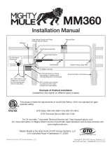
If you have any questions or concerns, please contact our Technical Service Department
Monday thru Friday 8:00 am to 5:00 pm (ET) at 1-800-543-1236 or 850-575-4144.
GTO, Inc. • 3121 Hartsfield Road • Tallahassee, Florida 32303
Telephone (850) 575-0176 • Fax (850) 575-8912 • website www.gtoinc.com
The contents of all material available on this installation manual are copyrighted by GTO, Inc. (“GTO”), unless otherwise indicated. All rights are reserved by GTO, and content may not be
reproduced, downloaded, disseminated, published, or transferred in any form or by any means, except with the prior, written permission of GTO. Any reprinting of GTO publications is by
permission only. Copyright infringement is a violation of federal law.
GTO®, GTO/PRO®, Mighty Mule® are registered trademarks of GTO, Inc. Professional Access Systems™ is a trademark of GTO, Inc. and are the exclusive property of GTO, Inc. (“GTO”).
All rights are reserved by GTO, and these marks may not be used, in any for without the prior, written permission of GTO.
  • Page 1 1
  • Page 2 2
  • Page 3 3
  • Page 4 4
  • Page 5 5
  • Page 6 6

GTO 350 Installation guide

Category
Garden tools
Type
Installation guide
This manual is also suitable for

Ask a question and I''ll find the answer in the document

Finding information in a document is now easier with AI