Ludlum Measurements 54 Series Owner's manual
- Type
- Owner's manual

LUDLUM MODEL 54 SERIES
54, 54A, 54R, 54R-1, & 54R-11
ARTICLE MONITORS
OPERATOR’S MANUAL
March 2021
Version 1.1.4 / 54001N03


LUDLUM MODEL 54 SERIES
54, 54A, 54R, 54R-1, & 54R-11
ARTICLE MONITORS
OPERATOR’S MANUAL
March 2021
Version 1.1.4 / 54001n03
LUDLUM MEASUREMENTS, INC.
501 OAK STREET, P.O. BOX 810
SWEETWATER, TEXAS 79556
325-235-5494, FAX: 325-235-4672


STATEMENT OF WARRANTY
Ludlum Measurements, Inc. warrants the products covered in this manual to be free
of defects due to workmanship, material, and design for a period of twelve months
from the date of delivery. The calibration of a product is warranted to be within its
specified accuracy limits at the time of shipment. In the event of instrument failure,
notify Ludlum Measurements to determine if repair, recalibration, or replacement is
required.
This warranty excludes the replacement of photomultiplier tubes, G-M and
proportional tubes, and scintillation crystals which are broken due to excessive
physical abuse or used for purposes other than intended.
There are no warranties, express or implied, including without limitation any implied
warranty of merchantability or fitness, which extend beyond the description of the
face there of. If the product does not perform as warranted herein, purchaser’s sole
remedy shall be repair or replacement, at the option of Ludlum Measurements. In no
event will Ludlum Measurements be liable for damages, lost revenue, lost wages, or
any other incidental or consequential damages, arising from the purchase, use, or
inability to use product.
RETURN OF GOODS TO MANUFACTURER
If equipment needs to be returned to Ludlum Measurements, Inc. for repair or calibration, please
send to the address below. All shipments should include documentation containing return shipping
address, customer name, telephone number, description of service requested, and all other necessary
information. Your cooperation will expedite the return of your equipment.
LUDLUM MEASUREMENTS, INC.
ATTN: REPAIR DEPARTMENT
501 OAK STREET
SWEETWATER, TX 79556
800-622-0828 325-235-5494
FAX 325-235-4672


Table of Contents
Introduction ................................................................................................................................................... 1
Features ......................................................................................................................................................... 3
Specifications ................................................................................................................................................ 4
Software License Agreement ........................................................................................................................ 6
Safety Considerations ................................................................................................................................... 8
ENVIRONMENTAL CONDITIONS FOR NORMAL USE ................................................................................... 8
REPLACEMENT OF FUSES ........................................................................................................................... 8
CLEANING PRECAUTIONS ........................................................................................................................... 8
LEAD SHIELDED DOORS ............................................................................................................................. 8
ELECTRICAL SAFETY PRECAUTIONS .......................................................................................................... 8
Operation .................................................................................................................................................... 10
CONTROLS AND FUNCTIONS .................................................................................................................... 10
POWER ON SELF TEST (POST) ................................................................................................................. 10
POWERING THE MODEL 54 ON ................................................................................................................. 11
POWERING THE MODEL 54 OFF ................................................................................................................ 11
NORMAL OPERATION ............................................................................................................................... 11
STATUS COLORS ....................................................................................................................................... 12
INSTRUMENT FAILURE ............................................................................................................................. 12
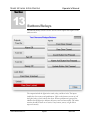
SUM CHANNELS ....................................................................................................................................... 13
SUM ZONE ALARM PRIORITY ................................................................................................................... 14
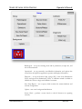
Supervisor ................................................................................................................................................... 15
TOUCH SCREEN OPERATION .................................................................................................................... 15
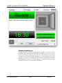
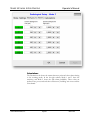
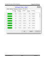
OPERATE SCREEN ..................................................................................................................................... 15
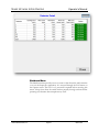
DETECTOR DETAIL SCREEN ..................................................................................................................... 17
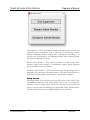
SHUTDOWN MENU ................................................................................................................................... 18
SETUP SCREEN ......................................................................................................................................... 19
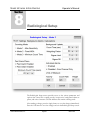
Radiological Setup ...................................................................................................................................... 22
COUNTING MODES ................................................................................................................................... 23
Mode 1 – Maximum Sensitivity ............................................................................................................................. 23
Mode 2 – Fixed MDA ............................................................................................................................................ 24
Mode 3 – Minimum Count Time ............................................................................................................................ 24
Count Mode Settings ............................................................................................................................................. 25
FAST CLEAN ............................................................................................................................................. 26
FAST ALARM ............................................................................................................................................ 27
UNITS OF MEASURE ................................................................................................................................. 27
UPDATING BACKGROUND ........................................................................................................................ 28
BACKGROUND ALARMS ........................................................................................................................... 28
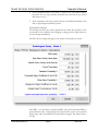
CALCULATIONS ........................................................................................................................................ 29
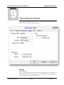
Operational Setup ........................................................................................................................................ 31

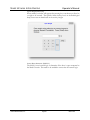
GENERAL .................................................................................................................................................. 31
Serial Number ....................................................................................................................................................... 31
Site ......................................................................................................................................................................... 32
Location................................................................................................................................................................. 32
Customer ID .......................................................................................................................................................... 32
Password ............................................................................................................................................................... 32
Alarm Hold ............................................................................................................................................................ 32
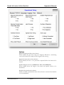
OPTIONS ................................................................................................................................................... 33
Require Employee ID to Start Count ..................................................................................................................... 33
Require Password to Clear Alarms ....................................................................................................................... 33
Enable Weight Sensors (CURRENTLY NOT IMPLEMENTED) ........................................................................... 33
Residual Contamination Check ............................................................................................................................. 33
Latch Failures ....................................................................................................................................................... 34
Number of Detectors ............................................................................................................................................. 34
Number of Doors ................................................................................................................................................... 34
Ingress Door Swing ............................................................................................................................................... 34
Door Logic ............................................................................................................................................................ 34
Show Alarm Result ................................................................................................................................................ 34
Show Counts as Activity ........................................................................................................................................ 34
Input Weight Manually .......................................................................................................................................... 35
Invert Door Sensors (SAM-11) .............................................................................................................................. 35
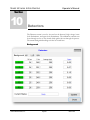
Detectors ..................................................................................................................................................... 36
BACKGROUND .......................................................................................................................................... 36
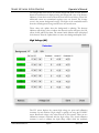
HIGH VOLTAGE (HV) ............................................................................................................................... 37
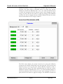
LOWER LEVEL DISCRIMINATOR (LLD) ................................................................................................... 38
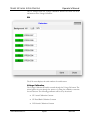
S/N ........................................................................................................................................................... 39
VOLTAGE CALIBRATION .......................................................................................................................... 39
HV Actual Calibration Constant ........................................................................................................................... 40
HV Read Back Calibration Constant .................................................................................................................... 42
LLD Actual Calibration Constant ......................................................................................................................... 43
ULD Actual Calibration Constant ........................................................................................................................ 44
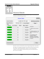
Source Check .............................................................................................................................................. 46
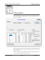
False Alarm ................................................................................................................................................. 47
Buttons/Relays ............................................................................................................................................ 49
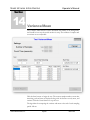
Variance/Mean ............................................................................................................................................ 50
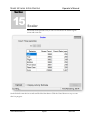
Scaler .......................................................................................................................................................... 52
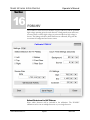
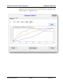
FOM-HV ..................................................................................................................................................... 53
SELECT DETECTORS FOR HV PLATEAU ................................................................................................... 53
COUNT TIME SETTINGS ............................................................................................................................ 54
SOURCE SIZE ............................................................................................................................................ 54
HV SETTINGS ........................................................................................................................................... 54
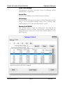
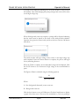
RUNNING THE FOM-HV .......................................................................................................................... 54
Efficiencies ................................................................................................................................................. 57
View Logs ................................................................................................................................................... 63

Changes ....................................................................................................................................................... 65
Recycling .................................................................................................................................................... 66
Lead Installation.......................................................................................................................................... 67
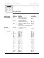
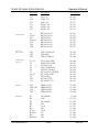
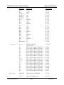
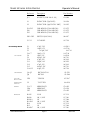
Parts List ..................................................................................................................................................... 68


Model 54 Series Article Monitors Operator’s Manual
Ludlum Measurements, Inc. Page 1 March 2021
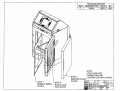
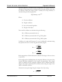
Introduction
The Model 54 Article Monitor is used to detect gamma radiation in or on small
articles, tools, and equipment. The interior volume of the chamber is 50.8 x 50.8
x 50.8 cm (20 x 20 x 20 in.). The chamber is shielded with lead, making it fairly
massive.
The Model 54A is a smaller version of the Model 54 with internal dimensions of
35.6 x 35.6 x 35.6 cm (14 x 14 x 14 in.). This version provides an option for
monitoring smaller articles. Although a smaller size, the Model 54A exhibits the
same features and operates in the same way as the Model 54.
The Model 54R, 54R-1, and 54R-11 are retrofit options that allow customers to
use an existing article monitor from another manufacturer, but with the Ludlum
Model 54 electronics. Existing detectors can also be replaced with Ludlum
detectors if needed.
The Model 54R-11, is a specific set of electronics designed to fit an existing
Thermo SAM-11 article monitor.
For the remainder of this manual, references to the Model 54 will include
the Model 54A and retrofit options unless otherwise noted.
The Model 54 is designed to be user-friendly. Users press only a single COUNT
button in normal operation and see status clearly on the 30.7 cm (12.1 in.) color
liquid crystal display (LCD). Instrument technicians have password-protected
access to advanced automated routines to calibrate or verify operation. The
Model 54 Article Monitor can be configured with several different options
including:
2.5 or 5.1 cm (1 or 2 in.) thick lead shielding
left or right-door swing
optional second LCD display
There are three counting modes to maximize throughput, sensitivity, or to fix
the count time. Several parameters can be modified to adjust the alarm set
point, including the false alarm probability, detection probability, background
sigma coefficient, and the composite sigma coefficient. Fast alarm and clean
options provide the ability to determine if an article is contaminated or clean
before the count cycle has ended.
Section
1

Model 54 Series Article Monitors Operator’s Manual
Ludlum Measurements, Inc. Page 2 March 2021
The model number identifies the configuration of the Article Monitor. The first
number is the basic series number. The second number is the number of
detectors. The third number indicates the thickness of the lead shielding. The
fourth number indicates the number of displays. So a Model 54-6-1-1 has the
following configuration:
6 detectors
2.5 cm (1 in.) lead shielding
1 LCD display

Model 54 Series Article Monitors Operator’s Manual
Ludlum Measurements, Inc. Page 3 March 2021
Features
True 4π counting geometry for optimized homogeneous efficiency.
Fast Alarm/Fast Clean counting technology for shorter counting cycles.
Large 30.7 cm (12.1 in.) color LCD with touch screen interface.
Three counting modes to maximize throughput, sensitivity, or fix the
count time.
Automatic background updating.
Contaminated detector check.
Individual detector and sum channel alarms.
Two levels of password security.
Door locks to control single or dual door operation.
5.1 cm (2 in.) thick lead shielding (option for 2.5 cm {1 in.}).
Rugged, easy-swing hinges.
Count, Background Update, and Alarm Acknowledge buttons.
Model 54: 50.8 x 50.8 x 50.8 cm (20 x 20 x 20 in.) inside dimensions
Model 54A: 35.6 x 35.6 x 35.6 cm (14 x 14 x 14 in.) inside dimensions
Single Board Computer (SBC) running a Windows Operating System
(Windows 7 at the time of this writing.)
Section
2

Model 54 Series Article Monitors Operator’s Manual
Ludlum Measurements, Inc. Page 4 March 2021
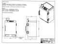
Specifications
CHAMBER
Internal Dimensions: Model 54: 50.8 x 50.8 x 50.8 cm (20 x 20 x 20 in.) (H x W x L)
Model 54A: 35.6 x 35.6 x 35.6 cm (14 x 14 x 14 in.) (H x W x L)
Detection Volume: Model 54: 130 L (4.6 ft3)
Model 54A: 45 L (1.6 ft3) for the Model 54A
Liner Material: 0.79 mm (0.031 in.) thick, stainless steel
Note: For the Model 54R or 54R-1, this depends on the customer’s existing system.
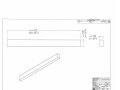
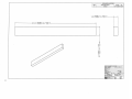
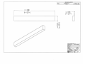
DETECTORS
Four or six detector configurations available
Scintillator: EJ-200 plastic
Size: Model 54: 48.3 x 48.3 x 5.1 cm (19 x 19 x 2 in.) (H x W x D)
Model 54A: 33.0 x 33.0 x 5.1 cm (13.0 x 13.0 x 2.0 in.) (H x W x D)
Model 54R-1 (4 each): 30.5 x 89 x 5.1 cm (12 x 35 x 2 in) (H x W x D)
Model 54R-1 (2 each): 30.5 x 61 x 5.1 cm (12 x 24 x 2 in) (H x W x D)
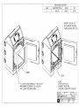
DOORS
Reversible door swing
Door hinges are heavy-duty rated, incorporating ball bearings for smooth operation
Door locks to control single (or dual) door operation
MECHANICAL
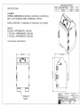
Dimensions: Model 54: 139 x 90.9 x 95.3 cm (54.7 x 35.8 x 37.5 in.) (H x W x D)
Model 54A: 94.0 x 68.6 x 80.0 cm (37.0 x 27.0 x 31.5 in.) (H x W x D)
Note: For the Model 54R or 54R-1, this depends on the customer’s existing system.
Section
3

Model 54 Series Article Monitors Operator’s Manual
Ludlum Measurements, Inc. Page 5 March 2021
Weight: 0 cm (0 in.) of lead: Model 54 is approximately 544 kg (1200 lb)
Model 54A is approximately 318 kg (700 lb)
2.5 cm (1 in.) of lead: Model 54 is approximately 1315 kg (2900 lb)
Model 54A is approximately 771 kg (1700 lb)
5.1 cm (2 in.) of lead: Model 54 is approximately 2087 kg (4600 lb)
Model 54A is approximately 1247 kg (2750 lb)
Lead is shipped separately and installed on site.
Model 54R: depends on the customer’s existing system.
Model 54R-1: weight of system without lead is
approximately 137 kg (303 lb)
ENVIRONMENTAL
Temperature: 0 to 50 °C (32 to 122 °F)
COUNTING
Three alarm modes to maximize throughput, sensitivity, or fix the count time
Alarms available for sum channels, sum zones, and individual detectors
Automatic background updating
Contaminated detector checking
False alarm control
Logs each use, operational test, and calibration
PERFORMANCE
Detects 2.2 nCi mixed 60Co/137 Cs source in under 5 seconds

Model 54 Series Article Monitors Operator’s Manual
Ludlum Measurements, Inc. Page 6 March 2021
Software License Agreement
BY INSTALLING THIS SOFTWARE, YOU ARE CONSENTING TO BE BOUND BY THIS AGREEMENT.
IF YOU DO NOT AGREE TO ALL OF THE TERMS OF THIS AGREEMENT, DO NOT INSTALL THE
PRODUCT.
Single User License Grant: Ludlum Measurements, Inc. ("Ludlum") and its suppliers grant to Customer
("Customer") a nonexclusive and nontransferable license to use the Ludlum software ("Software") in
object code form solely on a single central processing unit owned or leased by Customer or otherwise
embedded in equipment provided by Ludlum.
Customer may make one (1) archival copy of the Software provided Customer affixes to such copy all
copyright, confidentiality, and proprietary notices that appear on the original.
EXCEPT AS EXPRESSLY AUTHORIZED ABOVE, CUSTOMER SHALL NOT: COPY, IN WHOLE OR
IN PART, SOFTWARE OR DOCUMENTATION; MODIFY THE SOFTWARE; REVERSE COMPILE OR
REVERSE ASSEMBLE ALL OR ANY PORTION OF THE SOFTWARE; OR RENT, LEASE,
DISTRIBUTE, SELL, OR CREATE DERIVATIVE WORKS OF THE SOFTWARE.
Customer agrees that aspects of the licensed materials, including the specific design and structure of
individual programs, constitute trade secrets and/or copyrighted material of Ludlum. Customer agrees not
to disclose, provide, or otherwise make available such trade secrets or copyrighted material in any form to
any third party without the prior written consent of Ludlum. Customer agrees to implement reasonable
security measures to protect such trade secrets and copyrighted material. Title to Software and
documentation shall remain solely with Ludlum.
LIMITED WARRANTY. Ludlum warrants that for a period of ninety (90) days from the date of shipment
from Ludlum: (i) the media on which the Software is furnished will be free of defects in materials and
workmanship under normal use; and (ii) the Software substantially conforms to its published
specifications. Except for the foregoing, the Software is provided AS IS. This limited warranty extends
only to Customer as the original licensee. Customer's exclusive remedy and the entire liability of Ludlum
and its suppliers under this limited warranty will be, at Ludlum or its service center's option, repair,
replacement, or refund of the Software if reported (or, upon request, returned) to the party supplying the
Software to Customer. In no event does Ludlum warrant that the Software is error free or that Customer
will be able to operate the Software without problems or interruptions.
This warranty does not apply if the software (a) has been altered, except by Ludlum, (b) has not been
installed, operated, repaired, or maintained in accordance with instructions supplied by Ludlum, (c) has
been subjected to abnormal physical or electrical stress, misuse, negligence, or accident, or (d) is used in
ultra hazardous activities.
DISCLAIMER. EXCEPT AS SPECIFIED IN THIS WARRANTY, ALL EXPRESS OR IMPLIED
CONDITIONS, REPRESENTATIONS, AND WARRANTIES INCLUDING, WITHOUT LIMITATION, ANY
IMPLIED WARRANTY OF MERCHANTABILITY, FITNESS FOR A PARTICULAR PURPOSE,
NONINFRINGEMENT OR ARISING FROM A COURSE OF DEALING, USAGE, OR TRADE
PRACTICE, ARE HEREBY EXCLUDED TO THE EXTENT ALLOWED BY APPLICABLE LAW. IN NO
Section
4
Page is loading ...
Page is loading ...
Page is loading ...
Page is loading ...
Page is loading ...
Page is loading ...
Page is loading ...
Page is loading ...
Page is loading ...
Page is loading ...
Page is loading ...
Page is loading ...
Page is loading ...
Page is loading ...
Page is loading ...
Page is loading ...
Page is loading ...
Page is loading ...
Page is loading ...
Page is loading ...
Page is loading ...
Page is loading ...
Page is loading ...
Page is loading ...
Page is loading ...
Page is loading ...
Page is loading ...
Page is loading ...
Page is loading ...
Page is loading ...
Page is loading ...
Page is loading ...
Page is loading ...
Page is loading ...
Page is loading ...
Page is loading ...
Page is loading ...
Page is loading ...
Page is loading ...
Page is loading ...
Page is loading ...
Page is loading ...
Page is loading ...
Page is loading ...
Page is loading ...
Page is loading ...
Page is loading ...
Page is loading ...
Page is loading ...
Page is loading ...
Page is loading ...
Page is loading ...
Page is loading ...
Page is loading ...
Page is loading ...
Page is loading ...
Page is loading ...
Page is loading ...
Page is loading ...
Page is loading ...
Page is loading ...
Page is loading ...
Page is loading ...
Page is loading ...
Page is loading ...
Page is loading ...
Page is loading ...
Page is loading ...
Page is loading ...
Page is loading ...
-
 1
1
-
 2
2
-
 3
3
-
 4
4
-
 5
5
-
 6
6
-
 7
7
-
 8
8
-
 9
9
-
 10
10
-
 11
11
-
 12
12
-
 13
13
-
 14
14
-
 15
15
-
 16
16
-
 17
17
-
 18
18
-
 19
19
-
 20
20
-
 21
21
-
 22
22
-
 23
23
-
 24
24
-
 25
25
-
 26
26
-
 27
27
-
 28
28
-
 29
29
-
 30
30
-
 31
31
-
 32
32
-
 33
33
-
 34
34
-
 35
35
-
 36
36
-
 37
37
-
 38
38
-
 39
39
-
 40
40
-
 41
41
-
 42
42
-
 43
43
-
 44
44
-
 45
45
-
 46
46
-
 47
47
-
 48
48
-
 49
49
-
 50
50
-
 51
51
-
 52
52
-
 53
53
-
 54
54
-
 55
55
-
 56
56
-
 57
57
-
 58
58
-
 59
59
-
 60
60
-
 61
61
-
 62
62
-
 63
63
-
 64
64
-
 65
65
-
 66
66
-
 67
67
-
 68
68
-
 69
69
-
 70
70
-
 71
71
-
 72
72
-
 73
73
-
 74
74
-
 75
75
-
 76
76
-
 77
77
-
 78
78
-
 79
79
-
 80
80
-
 81
81
-
 82
82
-
 83
83
-
 84
84
-
 85
85
-
 86
86
-
 87
87
-
 88
88
-
 89
89
-
 90
90


Ludlum Measurements 54 Series Owner's manual
- Type
- Owner's manual
Ask a question and I''ll find the answer in the document
Finding information in a document is now easier with AI
Related papers
-
Ludlum Measurements 240 Series Software Owner's manual
-
-
-
-
-
-
-
-
-
Other documents
-
 LUDLUM Model 6 User manual
-
LUDLUM M30 Operating instructions
-
 LUDLUM 26-3 User guide
-
 LUDLUM 26-2 User manual
-
LUDLUM 26s User manual
-
Ransomes 62214-A Owner's manual
-
Slant/Fin VICTORY II VHS Series Installation And Operating Instructions Manual
-
 ETAS MDA User manual
-
Slant/Fin Boiler B-200A User manual
-


